Note : Les descriptions sont présentées dans la langue officielle dans laquelle elles ont été soumises.
CA 03099204 2020-11-03
WO 2019/238698 PCT/EP2019/065237
1
STORAGE SYSTEM
Field of the invention
The present invention relates to an automated storage and retrieval system, a
transport vehicle for use in an automated storage and retrieval system and a
method
for use of an automated storage and retrieval system.
Background
Figs. 1A and 2B disclose a typical prior art automated storage and retrieval
system
1 with a framework structure 100. Figs. 1B and 2B disclose prior art container
handling vehicles 200,300 operating in the system 1 disclosed in Figs. lA and
2A,
respectively.
The framework structure 100 defines a storage grid 104 comprising a plurality
of
upright members 102 and optionally a plurality of horizontal members 103
supporting the upright members 102. The members 102, 103 may typically be made
of metal, e.g. extruded aluminium profiles.
The storage grid 104 comprises multiple grid columns 112. A large majority of
the
grid columns are also termed storage columns 105, in which storage containers
106,
also known as bins, are stacked one on top of another to form stacks 107.
Each storage container 106 may typically hold a plurality of product items
(not
shown), and the product items within a storage container 106 may be identical
or
may be of different product types depending on the application.
The storage grid 104 guards against horizontal movement of the of storage
containers 106 in the stacks 107, and guides vertical movement of the
containers
106, but does normally not otherwise support the storage containers 106 when
stacked.
The automated storage and retrieval system 1 comprises a rail system 108 (or a
top
rail grid) arranged in a grid pattern across the top of the storage grid 104,
on which
rail system 108 a plurality of container handling vehicles 200,300 (as
exemplified in
Figs. 1B and 2B) are operated to raise storage containers 106 from, and lower
storage containers 106 into, the storage columns 105, and also to transport
the
storage containers 106 above the storage columns 105. The horizontal extent of
one
of the grid cells 122 constituting the grid pattern is in Figs. 1A and 2A
marked by
thick lines.
Each grid cell 122 has a width which is typically within the interval of 30 to
150
cm, and a length which is typically within the interval of 50 to 200 cm. Each
grid
CA 03099204 2020-11-03
WO 2019/238698 PCT/EP2019/065237
2
opening 115 has a width and a length which is typically 2 to 10 cm less than
the
width and the length of the grid cell 122 due to the horizontal extent of the
rails
110,111.
The rail system 108 comprises a first set of parallel rails 110 arranged to
guide
movement of the container handling vehicles 200,300 in a first direction X
across
the top of the frame structure 100, and a second set of parallel rails 111
arranged
perpendicular to the first set of rails 110 to guide movement of the container
handling vehicles 200,300 in a second direction Y which is perpendicular to
the first
direction X. In this way, the rail system 108 defines the upper ends of the
grid
columns 112 above which the container handling vehicles 200,300 can move
laterally, i.e. in a plane which is parallel to the horizontal X-Y plane.
Commonly, at
least one of the sets of rails 110,111 is made up of dual-track rails allowing
two
container handling vehicles to pass each other on neighbouring grid cells 122.
Dual-
track rails are well-known and disclosed in for instance WO 2015/193278 Al and
WO 2015/140216 Al, the contents of which are incorporated herein by reference.
Each prior art container handling vehicle 200,300 comprises a vehicle body and
a
wheel arrangement of eight wheels 201,301, wherein a first set of four wheels
enable the lateral movement of the container handling vehicles 200,300 in the
X
direction and a second set of the remaining four wheels enable the lateral
movement
in the Y direction. One or both sets of wheels in the wheel arrangement can be
lifted
and lowered, so that the first set of wheels and/or the second set of wheels
can be
engaged with the respective set of rails 110, 111 at any one time.
Each prior art container handling vehicle 200,300 also comprises a lifting
device
(not shown) for vertical transportation of storage containers 106, e.g.
raising a
storage container 106 from, and lowering a storage container 106 into, a
storage
column 105. The lifting device comprises one or more gripping/engaging devices
(not shown) which are adapted to engage a storage container 106, and which
gripping/engaging devices can be lowered from the vehicle 201,301 so that the
position of the gripping/engaging devices with respect to the vehicle 201,301
can be
adjusted in a third direction Z which is orthogonal the first direction X and
the
second direction Y.
Conventionally, and also for the purpose of this application, Z=1 identifies
the
uppermost layer of the grid 104, i.e. the layer immediately below the rail
system
108, Z=2 the second layer below the rail system 108, Z=3 the third layer etc.
In the
prior art storage grid disclosed in Figs. lA and 2A, Z=8 identifies the
lowermost,
bottom layer of the grid 104. Consequently, as an example, and using the
Cartesian
coordinate system X, Y, Z indicated in Figs. lA and 2B, the storage container
identified as 106' in Fig. 1 can be said to occupy grid location or cell X=10,
Y=2,
CA 03099204 2020-11-03
WO 2019/238698 PCT/EP2019/065237
3
Z=3. The container handling vehicles 200,300 can be said to travel in layer
Z=0 and
each grid column can be identified by its X and Y coordinates.
Each container handling vehicle 200 comprises a storage compartment or space
(not
shown) for receiving and stowing a storage container 106 when transporting the
storage container 106 across the top of the storage grid 104. The storage
space may
comprise a cavity arranged centrally within the vehicle body, e.g. as is
described in
W02014/090684A1, the contents of which are incorporated herein by reference.
Alternatively, the container handling vehicles 300 may have a cantilever
construction as described in NO317366, the contents of which are also
incorporated
herein by reference.
The container handling vehicles 200 may have a footprint, i.e. an extent in
the X
and Y directions, which is generally equal to the horizontal area of a grid
cell 122,
i.e. the extent of a grid cell 122 in the X and Y directions, e.g. as is
described in
W02015/193278A1, the contents of which are incorporated herein by reference.
Alternatively, the container handling vehicles 200 may have a footprint which
is
larger than the horizontal area of a grid cell 122, e.g. as is disclosed in
W02014/090684A1.
In a storage grid 104, a majority of the grid columns 112 are storage columns
105, i.e.
grid columns where storage containers 106 are stored in stacks 107. However, a
grid 104
normally has at least one grid column 112 which is not used for storing
storage
containers 106, but is arranged at a location wherein the container handling
vehicles
200,300 can drop off and/or pick up storage containers 106 so that they can be
transported to a second location (not shown) where the storage containers 106
can be
accessed from outside of the grid 104 or transferred out of or into the grid
104. Within
the art, such a location is normally referred to as a "port" and the grid
column at which
the port is located may be referred to as a transfer column 119,120. The drop-
off and
pick-up ports are the upper ends/openings of a respective transfer column
119,120.
The prior art storage grids 104 in Figs. lA and 2A comprise two transfer
columns
119 and 120. The first transfer column 119 may for example comprise a
dedicated
drop-off port where the container handling vehicles 200,300 can drop off
storage
containers 106 to be transported through the transfer column 119 and further
to e.g.
a picking/stocking station, and the second transfer column 120 may comprise a
dedicated pick-up port where the container handling vehicles 200,300 can pick
up
storage containers 106 that have been transported through the transfer column
120
from e.g. a picking/stocking station. A storage container may be transported
through
a transfer column by use of the lifting device of a container handling vehicle
200,300 or by use of a storage container lift arranged in the transfer column.
Each
CA 03099204 2020-11-03
WO 2019/238698 PCT/EP2019/065237
4
of the ports of the first and second transfer column may be suitable for both
pick-up
and drop-off of storage containers.
The second location may typically be a picking/stocking station, wherein
product
items are removed from and/or positioned into the storage containers 106. In a
picking/stocking station, the storage containers 106 are normally never
removed
from the automated storage and retrieval system 1 but are returned into the
storage
grid 104 once accessed.
For monitoring and controlling the automated storage and retrieval system 1,
e.g.
monitoring and controlling the location of respective storage containers 106
within
the storage grid 104; the content of each storage container 106; and the
movement
of the container handling vehicles 200,300 so that a desired storage container
106
can be delivered to the desired location at the desired time without the
container
handling vehicles 200,300 colliding with each other, the automated storage and
retrieval system 1 comprises a computerized control system (not shown) which
typically comprises a database for keeping track of the storage containers
106.
A conveyor system comprising conveyor belts or rollers is commonly employed to
transport the storage containers from a lower end of the transfer columns
119,120 to e.g.
a picking/stocking station.
A conveyor system may also be arranged to transfer storage containers between
different
storage grids, e.g. as is described in W02014/075937A1, the contents of which
are
incorporated herein by reference.
Further, W02016/198467A1, the contents of which are incorporated herein by
reference,
discloses an example of a prior art access system having conveyor belts (Figs.
5a and 5b
in W02016/198467A1) and a frame mounted rail (Figs. 6a and 6b in
W02016/198467A1) for transporting storage containers between transfer columns
and
stations where operators can access the storage containers.
When a storage container 106 stored in the storage grid 104 disclosed in Fig.
lA is to be
accessed, one of the container handling vehicles 200,300 is instructed to
retrieve the
target storage container 106 from its position in the grid 104 and transport
it to or through
the transfer column 119. This operation involves moving the container handling
vehicle
200,300 to a grid location above the storage column 105 in which the target
storage
container 106 is positioned, retrieving the storage container 106 from the
storage column
105 using the container handling vehicle's lifting device (not shown), and
transporting
the storage container 106 to the transfer column 119. If the target storage
container 106 is
located deep within a stack 107, i.e. with one or a plurality of other storage
containers
positioned above the target storage container 106, the operation also involves
temporarily
moving the above-positioned storage containers prior to lifting the target
storage
container 106 from the storage column 105. This step, which is sometimes
referred to as
CA 03099204 2020-11-03
WO 2019/238698 PCT/EP2019/065237
"digging" within the art, may be performed with the same container handling
vehicle
200,300 that is subsequently used for transporting the target storage
container 106 to the
transfer column, or with one or a plurality of other cooperating container
handling
vehicles 200,300. Alternatively, or in addition, the automated storage and
retrieval
5 system 1 may have container handling vehicles 200,300 specifically
dedicated to the task
of temporarily removing storage containers 106 from a storage column 105. Once
the
target storage container 106 has been removed from the storage column 105, the
temporarily removed storage containers can be repositioned into the original
storage
column 105. However, the removed storage containers may alternatively be
relocated to
other storage columns 105.
When a storage container 106 is to be stored in the grid 104, one of the
container
handling vehicles 200,300 is instructed to pick up the storage container 106
from the
transfer column 120 and to transport it to a grid location above the storage
column 105
where it is to be stored. After any storage containers positioned at or above
the target
position within the storage column stack 107 have been removed, the container
handling
vehicle 200,300 positions the storage container 106 at the desired position.
The removed
storage containers may then be lowered back into the storage column 105 or
relocated to
other storage columns 105.
A problem associated with known automated storage and retrieval systems 1 is
that the
area surrounding the pick-up and drop-off ports may become congested with
container
handling vehicles 200,300 instructed to drop off or pick up storage containers
106. This
may seriously impede the operation of the automated storage and retrieval
system 1. In
small systems this situation may possibly be alleviated by adding further
transfer
columns to the grid, as this will allow the container handling vehicles
200,300 to be
distributed among a larger number of ports of transfer columns in order to
avoid
congestion. However, if further ports and columns are added, the number of
picking/stocking stations as well as the conveyor system infrastructure must
be increased.
This requires space, which may not necessarily be available. Also, adding
conveyor
system infrastructure and additional picking/stocking stations is costly.
In the prior art solutions for transfer of storage containers out of or into
the storage grid,
the ports and the respective transfer columns 119,120 are required to be
arranged at a
grid column 112 in/at the periphery of the storage grid, or the ports are
arranged at an
extension of the rail system 108 extending beyond the grid columns 112 at the
periphery
of the storage grid 104. Examples of such prior art solutions are disclosed in
for instance
W02014/203126 Al, WO 2012/026824 Al, W02016/198467 Al and WO
2017/211596 Al. This requirement entails that the number of transfer columns
119,120
and any associated structure for storage container handling, such as
picking/stocking
stations, are restricted by the available space at the periphery of the
storage grid. Further,
by having the transfer columns 119,120 arranged at or outside the periphery of
the
storage grid, the container handling vehicles are often required to travel
long distances
CA 03099204 2020-11-03
WO 2019/238698 PCT/EP2019/065237
6
upon the storage grid to reach the closest port. The latter is a hindrance to
obtaining an
optimum efficiency, in particular when operating large storage grids, wherein
the
distance from a centre section of the storage grid to the periphery is long.
A further issue with the prior art solutions is the lack of flexibility
regarding the handling
of storage containers exiting or entering the storage grid. That is, a storage
container
from which an item is to be picked or in which an item is to be stocked must
be delivered
to a port specifically designated for the purpose of picking/stocking items.
Similarly, a
storage container exiting the grid for the purpose of being transported to
e.g. a
neighbouring storage grid or assembly line must be delivered to a port
specifically
designated for this purpose.
Some of the above-mentioned issues regarding flexibility may be solved by use
of
extensive conveyor systems, i.e. conveyor belts, rollers etc., as well as
dedicated storage
container lifts. However, such systems are expensive, service intensive and
are
vulnerable to single point of failure events that may disrupt the operation of
the storage
system.
An efficiency issue with prior art automated storage and retrieval systems 1
is that the
separate drop-off ports and pick-up ports of the transfer columns 119,120
require the
container handling vehicles 200,300 to move to a storage column 105 or a pick-
up port
after drop-off to retrieve a new storage container 106. Likewise, the
container handling
vehicles 200,300 have to be empty of a storage container 106 when they are
sent to a
pick-up port 120 to pick up a storage container. This is often inefficient and
causes
increased congestion around the ports, as container handling vehicles 200,300
are
moving around on the grid without a storage container 106 as payload.
Yet an efficiency issue with prior art automated storage and retrieval systems
is the way
items to be shipped out are transported from a picking/stocking stations,
wherein the
items are packed in boxes, to a loading station wherein the packed items are
for instance
loaded onto a truck for transport to a customer.
In view of the above, the aim of the present invention is to provide an
automated storage
and retrieval system, and a method for operating such a system, that solves or
at least
mitigates one or more of the aforementioned problems related to the use of
prior art
storage and retrieval systems.
The main objective of the present invention is to provide an automated storage
and
retrieval system in which items may be transported between a picking/stocking
station of
the storage system and a site external to the storage system in a more
efficient manner.
CA 03099204 2020-11-03
WO 2019/238698 PCT/EP2019/065237
7
Summary of the invention
The present invention is defined by the appended claims and in the following:
In a first aspect, the present invention provides a storage system comprising
a
storage grid structure having a top rail grid upon which container handling
vehicles
work to store and retrieve storage containers in and from storage columns
beneath
the top rail grid, wherein the storage system comprises multiple transfer
rails
forming a horizontal transfer rail grid arranged at a level below the top rail
grid, at
least one transport vehicle operating on the transfer rail grid, a
picking/stocking
station for picking/stocking items between a storage container and a packaging
box,
and an unloading/loading assembly for unloading/loading packaging boxes
containing such items, the transport vehicle is arranged to move upon the
transfer
rail grid in two perpendicular directions and comprises a carrier platform,
wherein
the transfer rail grid is arranged to allow access for the transport vehicle
to transport
one or more packaging boxes at a time between the picking/stocking station and
the
unloading/loading assembly.
In other words, the transfer rail grid extends between the picking/stocking
station
and the unloading/loading assembly such that an item picked from a storage
container and loaded onto the transport vehicle may be transported by the
transport
vehicle from the picking/stocking station to the unloading/loading assembly.
In other words, the picking/stocking station is for picking/stocking items
from/in a
storage container after retrieving the storage container from the storage grid
or
before introducing the storage container into the storage grid. The
picking/stocking
station may be operatively connected to a transfer column of the storage grid
structure, such that a storage container may be transferred between the
picking/stocking station and a storage column.
The unloading/loading assembly may comprise any of a pallet lifter and/or a
conveyor system arranged to load/unload packaging boxes and/or pallets to/from
the
transport vehicle.
In other words, the transfer rail grid may be arranged such that the transport
vehicle
can access or be arranged at the unloading/loading assembly.
Alternatively, the storage system may be defined as comprising the
unloading/loading assembly.
In an embodiment of the storage system, the transfer rail grid may comprise a
transfer grid area at which the unloading/loading assembly is arranged.
CA 03099204 2020-11-03
WO 2019/238698 PCT/EP2019/065237
8
In an embodiment of the storage system, the carrier platform may be arranged
to
support a pallet. In other words, the transport vehicle may be suitable for
transporting one or more packaging boxes arranged on a pallet between the
picking/stocking station and the unloading/loading assembly.
In an embodiment of the storage system, the storage grid structure may
comprise
vertical column profiles defining multiple storage columns, in which storage
containers can be stored one on top of another in vertical stacks, and at
least one
transfer column, the column profiles are interconnected at their upper ends by
top
rails forming the horizontal top rail grid upon which the container handling
vehicles
may move in two perpendicular directions.
In an embodiment of the storage system, the transport vehicle may have a wheel
arrangement comprising a first set of wheels enabling movement of the
transport
vehicle in a first direction and a second set of wheels enabling movement of
the
transport vehicle in a second direction perpendicular to the first direction,
and each
set of wheels comprises at least two pairs of wheels arranged on opposite
sides of
the transport vehicle.
In an embodiment of the storage system, the carrier platform may comprise a
conveyor assembly arranged to move an item arranged on the carrier platform in
a
horizontal direction off the transport vehicle. The conveyor assembly may
comprise
any suitable conveyor solution, such as multiple rollers, a belt conveyor
and/or a
chain conveyor. The item movable by the conveyor assembly may be any type of
packaging boxes, pallets and storage containers.
In an embodiment of the storage system, the transport vehicle may comprise at
least
two adjacently connected wheel base units upon which the carrier platform is
arranged. Each wheel base unit may feature a wheel arrangement, wherein a
first set
of wheels enable movement of the transport vehicle in the first direction upon
the
transfer rail grid and a second set of wheels enable movement in the second
direction, and each set of wheels comprises two pairs of wheels arranged on
opposite sides of the wheel base unit.
In an embodiment of the storage system, each wheel arrangement may comprise
eight wheels and each set of wheels may comprise four wheels.
One or both sets of wheels in the wheel arrangement may be lifted and lowered,
so
that the first set of wheels and/or the second set of wheels can be engaged
with the
respective set of rails at any one time.
CA 03099204 2020-11-03
WO 2019/238698 PCT/EP2019/065237
9
In an embodiment of the storage system, each wheel base unit may have a
horizontal periphery fitting within the horizontal area defined by a grid cell
of the
transfer rail grid.
In an embodiment of the storage system, the carrier platform may be sized to
accommodate at least two of the storage containers side by side. The carrier
platform may be sized to accommodate four of the storage containers,
preferably
adjacently arranged in a two by two configuration. An advantage of having the
carrier platform sized to accommodate at least two storage containers is the
possibility of using the transport vehicle for loading or retrieving storage
containers
to/from the storage grid structure. This feature may for instance facilitate
the initial
loading of storage containers to the storage system and the retrieval of used
storage
containers from the storage grid structure to be replaced due to wear.
In an embodiment of the storage system, the transport vehicle may comprise
four
connected wheel base units, preferably connected in a two by two
configuration. In
other words, the four wheel base units are adjacently arranged two by two.
In an embodiment of the storage system, at least the transfer rails may extend
in one
of two perpendicular directions of the transfer rail grid are dual-track
rails, such that
the transport vehicle may pass another transport vehicle upon an adjacent grid
cell
of the transfer rail grid when moving in the one direction.
In an embodiment of the storage system, the storage grid structure may
comprise at
least one horizontal transfer section, and
the storage system may comprise multiple container transfer vehicles arranged
to
move upon the transfer rail grid in at least one horizontal direction, and
- the transfer section is arranged at a level below the top rail grid and
extends from an external side of the storage grid structure to a position
below the at least one transfer column and comprises at least a section of
the transfer rail grid upon which section the container transfer vehicles
may pass each other and move in two perpendicular horizontal directions;
and
- each of the container transfer vehicles comprises a container carrier for
carrying a storage container and a single wheel base unit; and
wherein the at least one transfer column extends from the top rail grid to the
transfer section, such that a storage container may be transferred between the
top
rail grid and the container carrier of one of the container transfer vehicles.
In other words, the at least one transfer column may extend from the top rail
grid to
the transfer section, such that a storage container may be transferred between
the
CA 03099204 2020-11-03
WO 2019/238698 PCT/EP2019/065237
top rail grid and the container carrier of one of the container transfer
vehicles when
the container transfer vehicle is arranged on the transfer rail grid at a
position below
the transfer column.
5 The at least one transfer column may also be defined as a column for
vertical
transfer of a storage container between different levels of the grid
structure,
preferably by use of a container handling vehicle.
The transfer section may in other words be defined as being arranged at a
level
10 below the level of the top rail grid.
In an embodiment of the storage system, the transfer grid area may be
accessible by
the container transfer vehicles and may be termed a multi-use transfer grid
area.
In an embodiment of the storage system, at least the transfer rails may extend
in one
of two perpendicular directions of the transfer rail grid may be dual-track
rails, such
that the container transfer vehicles and/or the transport vehicles may pass
each other
upon adjacent grid cells of the transfer rail grid when moving in the one
direction.
In other words, the transfer rails of the transfer rail grid may extend in two
perpendicular horizontal directions, and at least the transfer rails extending
in one
of the two perpendicular directions of the transfer rail grid may be dual-
track rails,
such that the container transfer vehicles and/or the transport vehicles may
pass each
other upon adjacent grid cells of the transfer rail grid when moving in the
one
direction
In an embodiment of the storage system, the transfer rails may be dual-track
rails,
such that the container transfer vehicles and/or the transport vehicles may
pass each
other upon adjacent grid cells of the transfer rail grid.
In an embodiment of the storage system, each of the container transfer
vehicles may
have a horizontal periphery fitting within the horizontal area defined by a
grid cell
of the transfer rail grid. In other words, the transfer rail grid may comprise
multiple
grid cells defined by the transfer rail grid, and each of the container
transfer
vehicles may have a horizontal periphery fitting within the horizontal area
defined
by one of the grid cells of the transfer rail grid, such that the container
transfer
vehicles may pass each other upon adjacent grid cells of the transfer rail
grid; in
other words, such that the container transfer vehicles may pass each other
when
moving on adjacent grid cells of the transfer rail grid.
In an embodiment of the storage system, the height of the transfer section may
be
sufficient to allow a container transfer vehicle to travel within the transfer
section
when carrying a storage container.
CA 03099204 2020-11-03
WO 2019/238698 PCT/EP2019/065237
11
The transfer rails may be defined as forming, providing, and/or being a part
of, the
transfer rail grid upon which the container transfer vehicles may move in at
least
one horizontal directions. Further, the container transfer vehicles may move
in two
perpendicular horizontal directions upon at least the section of the transfer
rail grid
being part of the transfer section. In other words, at least the transfer rail
grid being
part of the transfer section provides at least two perpendicular transfer
vehicle
paths, allowing a container transfer vehicle to move upon the transfer rail
grid in
two perpendicular directions.
In an embodiment of the storage system, at least a part of the transfer rail
grid may
be formed or provided by transfer rails arranged external to the storage grid.
In
other words, at least a part of the transfer rail grid may be arranged
external to the
storage grid.
In an embodiment of the storage system, the design of the transfer rails and
the
transfer rail grid may be similar, or identical, to the top rails and the top
rail grid,
respectively.
In an embodiment of the storage system, the transfer rail grid and the top
rail grid
may have substantially similar or identical dimensions. In other words, the
transfer
rails and the top rails provide respective rail grids having grid cells of the
same
horizontal extent and/or dimension. This feature is advantageous in that it
allows for
multiple adjacent transfer columns, through which storage containers may be
transferred simultaneously to respective adjacent container transfer vehicles
arranged in the transfer section.
In an embodiment of the storage system, the transfer rail grid may extend from
the
position below the at least one transfer column to a second position external
to the
storage grid structure. In other words, the transfer rail grid extends from
the
position below the at least one transfer column to a second position external
to the
storage grid structure, such that a container transfer vehicle may move from
the
position below the at least one transfer column to the second position.
In an embodiment of the storage system, the transfer rails may provide at
least one
transfer vehicle path extending from a position below the at least one
transfer
column to a second position external to the storage grid structure, i.e. such
that a
container transfer vehicle may move from the position below the at least one
transfer column to the second position. The transfer rails may provide a
plurality of
transfer vehicle paths extending from a position below the at least one
transfer
column to the second position external to the storage grid structure.
CA 03099204 2020-11-03
WO 2019/238698 PCT/EP2019/065237
12
In an embodiment of the storage system, the wheel arrangement of each
container
transfer vehicle may comprise eight wheels, wherein a first set of four wheels
enable the lateral movement of the container transfer vehicle in a first
direction and
a second set of the remaining four wheels enable the lateral movement in a
second
direction being perpendicular to the first direction. One or both sets of
wheels in the
wheel arrangement is connected to a wheel lifting mechanism and can be lifted
and
lowered, so that the first set of wheels and/or the second set of wheels can
be
engaged with the respective set of transfer rails of the transfer rail grid at
any one
time.
In an embodiment of the storage system, each of the container handling
vehicles
may comprise a wheel arrangement similar to the wheel arrangement of the
container transfer vehicles, for engaging the respective set of top rails of
the top rail
grid.
In an embodiment of the storage system, the at least one transfer column may
extend from the top rail grid to the transfer section, such that a container
handling
vehicle may transfer a storage container between the top rail grid and the
container
carrier of one of the container transfer vehicles. Each of the container
handling
vehicles may comprise a lifting device for vertical transfer of a storage
container.
In an embodiment of the storage system, the transfer section may extend from a
first
opening at an external side of the storage grid structure to at least a second
opening
at an external side of the storage grid structure. In other words, the
transfer section
extends through an internal section of the storage grid structure from a first
opening
at an external side of the storage grid structure to at least a second opening
at the
same or different external side of the storage grid structure The term
"opening" is
intended to mean a gap in the storage grid structure through which gap (or
opening)
at least one container transfer vehicle may pass while carrying a storage
container.
Preferably, the first and/or second opening have a width allowing the passage
of at
least two container transfer vehicles simultaneously.
In an embodiment of the storage system, the first and second openings may be
arranged at separate external sides of the storage grid structure, preferably
the first
and second openings are arranged at opposite external sides of the storage
grid
structure.
In an embodiment of the storage system, the transfer rails and/or the transfer
rail
grid may provide at least two adjacent transfer vehicle paths, such that at
least two
of the container transfer vehicles may pass each other in the transfer
section, i.e.
may pass each other when moving on the transfer rails or the transfer rail
grid in the
transfer section. Preferably the transfer rail grid comprises dual-track rail
allowing
CA 03099204 2020-11-03
WO 2019/238698 PCT/EP2019/065237
13
the container transfer vehicles to pass each other at adjacent grid cells of
the
transfer rail grid. In a further embodiment, the transfer rails, or the
transfer rail grid,
provides at least three transfer vehicle paths, such that at least three
container
transfer vehicles may pass each other in one direction within the transfer
section.
In an embodiment, the storage system may comprise multiple transfer columns.
In an embodiment of the storage system, the transfer section may extend below
the
multiple transfer columns. Preferably, the transfer section extends below
multiple
adjacent transfer columns.
In an embodiment of the storage system, the multiple transfer columns may be
arranged above one of the transfer vehicle paths.
In an embodiment, each of the multiple transfer columns may be arranged above
a
grid cell of the transfer rail grid and may be arranged above only one grid
cell i.e.
above a respective grid cell of the transfer rail grid.
In a further embodiment, the multiple transfer columns may be arranged above
only
one of several (e.g. two or three) transfer vehicle paths. In this manner, one
(or a
single) vehicle path may be dedicated to container transfer vehicles receiving
or
delivering storage containers from/to the at least one transfer column, while
the
remaining vehicle paths are dedicated for transfer/movement of container
transfer
vehicles, optionally carrying a storage container, out of or into the transfer
section.
In an embodiment of the storage system, the transfer rail grid may extend from
an
external side of the storage grid to a second position external to the storage
grid
structure.
In an embodiment of the storage system, the transfer rail grid may extend from
the
position below the at least one transfer column to a second position external
to the
storage grid structure. The second position may be at any suitable area,
arrangement
or station for further processing or transfer of a storage container or its
content, or
at any suitable position for parking of a container transfer vehicle, e.g. a
charging
station for the battery driving the container transfer vehicle or a temporary
storage
position of a storage container arranged on a container transfer vehicle.
In an embodiment of the storage system, the second position may be arranged at
a
picking/stocking station or area, such that an operator/robot may access the
content
of a storage container when arranged on a container transfer vehicle.
In an embodiment of the storage system, the second position may be below a
transfer column in a transfer section of a second storage grid structure. The
second
CA 03099204 2020-11-03
WO 2019/238698 PCT/EP2019/065237
14
storage grid structure comprises any of the features of the storage grid
structure of
the first aspect, and its embodiments, as defined above. Alternatively, the
first
aspect may be defined as a storage system comprising at least a first storage
grid
structure. In yet another embodiment, the transfer rails or transfer rail grid
extends
to a third position below a transfer column in a transfer section of a third
storage
grid structure. In a storage system comprising a first and a second storage
grid
structure, the second storage grid structure may be arranged at any level
and/or
position relative the first storage grid structure. When the first and a
second storage
grid structure are arranged at different levels, the transfer rail grid may
comprise a
container transfer vehicle lift for lifting a container transfer vehicle
between
separate levels of the transfer rail grid.
An advantage of the present invention is the possibility of easily
interconnecting
multiple separate storage grid structures and optionally any third-party
storage
system. This provides an increase in fire safety since the multiple storage
grid
structures are easily separated in a manner which prevents a fire from
spreading
from one storage grid structure to another. Further, the use of multiple
separate
storage grid structures allows for an improved utilization of available space
in a
storage house or location. Thus, the storage system of the first aspect may
also
comprise multiple storage grid structures. Each storage grid structure may be
interconnected by the transfer rail grid, such that the container transfer
vehicles may
move between any of the multiple storage grid structures.
In an embodiment of the storage system, the transfer rail grid may comprise an
interface connectable to a third-party storage, production and/or distribution
system.
The transfer rail grid may be integrable with a third-party storage,
production and
distribution system such that storage containers, packaging boxes and/or
pallets can
be transported between the storage system of the first aspect and the third-
party
storage, production and/or distribution system. The transfer rail grid may be
connectable to a third-party storage, production and distribution system such
as
production facility, a storage grid, assembling facility, reception or
shipping
location, etc. The connection may be by means of a connectable rail system or
a
conveyor system comprising conveyors employed to transport the storage
containers, packaging boxes and/or pallets between the transfer rail grid and
the
third-party storage, production and/or distribution system.
In an embodiment of the storage system, the second position may be at a
production
facility, e.g. an assembly line or assembly station.
In an embodiment of the storage system, the transfer rail grid may comprise at
least
one transfer vehicle path arranged external to the storage grid structure and
interconnecting the first and second openings of the transfer section arranged
at
CA 03099204 2020-11-03
WO 2019/238698 PCT/EP2019/065237
separate external sides (or side sections) of the storage grid structure, e.g.
such that
the transfer section extends between two opposite sides/walls of the storage
grid.
In an embodiment of the storage system, the at least one transfer column may
be
5 spaced from the horizontal periphery of the storage grid structure, i.e.
the at least
one transfer column is separated from the periphery of the storage grid
structure by
at least one column, e.g. a storage column.
In an embodiment of the storage system, the transfer section may extend to a
section
10 or part of, or a position within, the storage grid structure wherein the
horizontal
distance to any external side of the storage grid corresponds to the width of
at least
five adjacent grid columns or wherein the horizontal distance to the external
side of
the storage grid from which the transfer section extends corresponds to the
width of
at least five adjacent grid columns.
In an embodiment of the storage system, the length of the transfer section may
be
equal to at least half the length of an external side of the storage grid
structure,
which external side extends in the same direction as the transfer section.
In an embodiment of the storage system, the transfer section may comprise, or
may
be defined by, multiple horizontal ceiling profiles, vertical support profiles
arranged
at opposite ends of at least some of the ceiling profiles, e.g. at the
opposite ends of
at least some of the ceiling profiles, and the transfer rails, or a section of
the
transfer rail grid, arranged within the storage grid. The ceiling and support
profiles
may also be termed ceiling and support beams.
In an embodiment of the storage system, the multiple horizontal ceiling
profiles
may provide, or may be arranged as, a horizontal support grid.
In an embodiment of the storage system, the height of the transfer section may
be
defined by the distance between a lowermost surface of a ceiling profile and
an
upper surface of an opposing transfer rail of the transfer rail grid. In other
words,
the height is defined by the distance between a ceiling profile and an
opposing
transfer rail. Consequently, a container transfer vehicle carrying a storage
container
has a height being lower than the height of the transfer section when arranged
on
the transfer rail grid.
In an embodiment of the storage system, the width of the transfer section may
be
defined by the distance between the two support profiles connected at opposite
ends
of a common ceiling profile.
CA 03099204 2020-11-03
WO 2019/238698 PCT/EP2019/065237
16
In an embodiment of the storage system, the multiple transfer columns may be
defined by vertical column profiles extending from the top rail grid to the
ceiling
profiles and/or the support grid.
In an embodiment, the storage system may comprise multiple storage columns
arranged above the transfer section, which columns comprise stopper elements,
such
that storage containers arranged in the storage columns are prevented from
entering
the transfer section.
In an embodiment, the storage system may comprise an operator access passage
arranged adjacent to at least one side of the transfer section. The access
passage
may be arranged below multiple storage columns arranged adjacent to at least
one
side of the transfer section, which storage columns comprise stopper elements,
such
that storage containers arranged in the storage columns are prevented from
entering
the access passage. The access passage may run adjacent to the transfer
section,
such that an operator or service person may access a container transfer
vehicle
arranged on the transfer rail grid or vehicle path(s) within the transfer
section. The
stopper elements may be arranged at a suitable height for allowing an operator
to
walk beneath any storage container accommodated in the row of storage columns
adjacent to the transfer section.
In an embodiment, the transfer of the storage container between the top rail
grid and
the container carrier of one of the container transfer vehicles may be
performed by a
dedicated container lift arranged in the transfer column. However, the
transfer of
the storage container between the top rail grid and the container carrier of
one of the
container transfer vehicles is preferably performed by any of the container
handling
vehicles, i.e. by use of a lifting device of any of the container handling
vehicles.
The at least one transfer column is preferably arranged such that a container
handling vehicle may lower a storage container from the top rail grid, via the
transfer column, to a container transfer vehicle arranged below the transfer
column.
Consequently, the lower end of the transfer column has an opening allowing the
storage container to enter the transfer section from above.
In an embodiment of the storage system, the transfer section may extend to an
internal section of the storage grid structure, wherein the horizontal
distance to an
external side, side wall or section of the storage grid corresponds to the
width of at
least five, at least six or at least seven adjacent grid columns. In other
words, the
transfer section may extend to a position below a transfer column being
separated
from any external side section of the storage grid structure. The transfer
column
may for example be separated from any external side section of the storage
grid
structure by at least five, at least six or at least seven adjacently arranged
storage
CA 03099204 2020-11-03
WO 2019/238698 PCT/EP2019/065237
17
columns, or may be arranged proximate to a center of the storage grid
structure.
Having a transfer section extending a sufficient length within the storage
grid
structure ensures that the distances between the storage columns and the
transfer
columns are minimized. Consequently, the container handling vehicles will
spend
less time travelling back and forth to the transfer columns and the operation
of the
system is optimized.
The container carrier may be arranged to receive a container from above and
hence
carry that container above the container transfer vehicle, e.g. carry the
container at a
level above a vehicle body of the container transfer vehicle. The storage
system
may be arranged such that in use containers are passed directly between
container
handling vehicles and container transfer vehicles.
The container transfer vehicle and/or the transport vehicle may comprise a
weighing
mechanism in order to measure the weight of a storage container, packaging box
and/or pallet. The weighing mechanism may for example be based on a
commercially available electronic weighing scale. The weighing mechanism may
provide information concerning the contents inside each storage container,
packaging box and/or pallet, such as the total weight, the number of units,
the
internal weight distribution and/or the location within the storage grid the
storage
container, packaging box and/or pallet should be placed.
The first aspect of the invention may alternatively be defined as a storage
system
comprising a storage grid structure and multiple container handling vehicles,
the
storage grid structure comprises vertical column profiles defining multiple
storage
columns, in which storage containers can be stored one on top of another in
vertical
stacks, and at least one transfer column, the column profiles are
interconnected at
their upper ends by top rails forming a horizontal top rail grid upon which
the
container handling vehicles may move in two perpendicular directions, the
container handling vehicles are able to retrieve storage containers from, and
store
storage containers in, the storage columns, and transport the storage
containers on
the storage grid structure,
wherein the storage system comprises multiple transfer rails forming a
horizontal
transfer rail grid arranged at a level below the top rail grid, at least one
transport
vehicle and a picking/stocking station,
the transport vehicle is arranged to move upon the transfer rail grid in two
perpendicular directions and comprises a carrier platform sized to accommodate
at
least two of the storage containers side by side,
CA 03099204 2020-11-03
WO 2019/238698 PCT/EP2019/065237
18
the picking/stocking station is for picking/stocking items from/in a storage
container,
the transfer rail grid comprises a transfer grid area arranged to allow access
to the
transport vehicle by an unloading/loading assembly for unloading/loading items
from/to the transport vehicle, and
the transfer rail grid extends between the picking/stocking station and the
unloading/loading assembly.
In a second aspect, the present invention provides a transport vehicle for a
storage
system according to any of the preceding claims, comprising a carrier platform
and
at least two adjacently connected wheel base units, the carrier platform
supported
upon the wheel base units, and each wheel base unit features a wheel
arrangement
having a first set of wheels enabling lateral movement of the transport
vehicle in a
first direction upon a rail grid and a second set of wheels enabling lateral
movement
of the transport vehicle in a second direction being perpendicular to the
first
direction.
In other words, each wheel base unit features a wheel arrangement having a
first set
of wheels enabling lateral movement of the wheel base unit, and consequently
the
transport vehicle, in a first direction upon a rail grid and a second set of
wheels
enabling lateral movement in a second direction being perpendicular to the
first
direction.
In an embodiment, each wheel arrangement may comprise eight wheels and each
set
of wheels may comprise four wheels.
In an embodiment, each set of wheels may comprise two pairs of wheels arranged
on opposite sides of the wheel base unit.
In an embodiment of the transport vehicle, one or both sets of wheels in the
wheel
arrangement can be lifted and lowered, so that the first set of wheels and/or
the
second set of wheels can be engaged with a respective set of rails of the rail
grid at
any one time.
The wheels may be arranged such that the first set of wheels may be in contact
with
a first pair of opposite rails of a grid cell of the rail grid, while the
second set of
wheels are arranged above a second pair of opposite rails of the same grid
cell, or
vice versa.
CA 03099204 2020-11-03
WO 2019/238698 PCT/EP2019/065237
19
In an embodiment of the transport vehicle, the rail grid upon which the
transport
vehicle may move features grid cells having a horizontal area within which a
horizontal periphery of the wheel base unit may fit or be accommodated. In
other
words, the wheel base unit has a horizontal periphery fitting within the
horizontal
area of a grid cell of the rail grid.
In an embodiment of the transport vehicle, the carrier platform may comprise a
conveyor assembly able to move an item arranged on the carrier platform in a
horizontal direction off the transport vehicle. In other words, the conveyor
assembly
is arranged such that an item arranged on the carrier platform may be
transferred off
the carrier platform in a horizontal direction.
In a third aspect, the present invention provides a method of transporting
items in a
storage system according to the first aspect, comprising the steps of:
- retrieving at least one item from a storage container arranged in the
picking/supply station;
- loading the item onto the transport vehicle;
- moving the transport vehicle from the picking/supply station to the
unloading/loading assembly;
- retrieving the item from the transport vehicle by use of the
unloading/loading assembly.
In a fourth aspect, the present invention provides a method of transporting
items
into a storage system according to the first aspect, comprising the steps of:
- supplying at least one item to the transport vehicle by use of the
unloading/loading assembly;
- moving the transport vehicle from the unloading/loading assembly to the
picking/supply station;
- retrieving the item from the transport vehicle; and
- loading the item into a storage container arranged in the picking/supply
station.
The term "transfer section" is in the present application intended to mean a
substantially horizontal tunnel/passageway and/or recess in the storage grid
structure, having at least one open end or side, i.e. opening, at an external
side or
wall of the storage grid. The opening allowing a container transfer vehicle to
enter/exit the transfer section from a position external to the storage grid
structure.
Alternatively, the term "transfer section" may be replaced by "transfer
section
space" or "transfer space".
CA 03099204 2020-11-03
WO 2019/238698 PCT/EP2019/065237
Short description of the drawings
The present invention is described in detail below by way of example only and
with
5 reference to the following drawings:
Figs. 1 and 2 are perspective views of a prior art automated storage and
retrieval
system, wherein fig. 1A and fig. 2A show the complete system and fig. 1B and
Fig.
2B show examples of prior art container handling vehicles suitable for use in
the
10 system.
Fig. 3 is a perspective view of a first exemplary storage grid for use in a
storage
system according to the invention.
15 Fig. 4 is a perspective side view of the storage grid in fig. 3.
Fig. 5 is a perspective view of the storage grid in figs. 3 and 4, featuring a
container
handling vehicle and a container transfer vehicle.
20 Fig. 6 is a perspective view of the storage grid in figs. 3 to 5,
wherein the storage
columns are stocked with storage containers.
Fig. 7 is a perspective view of a second exemplary storage grid for use in a
storage
system according to the invention.
Fig. 8 is a perspective view of the storage grid in fig. 6, featuring a
container
handling vehicle and a container transfer vehicle.
Fig. 9 is a perspective top view of a third exemplary storage grid for use in
a storage
system according to the invention.
Fig. 10 is a perspective side view of a third exemplary storage grid for use
in a
storage system according to the invention.
Fig. 11 is a schematic top view of an exemplary storage system according to
the
invention.
Fig. 12 is a detailed view of a section of the storage system in fig. 8.
Fig. 13 is a perspective view of a storage system according to the invention.
CA 03099204 2020-11-03
WO 2019/238698 PCT/EP2019/065237
21
Figs. 14A and 14B are perspective views of an exemplary container transfer
vehicle
for use in a storage system according to the invention.
Figs. 15A,15B and 15C are perspective views of a wheel base unit of the
container
transfer vehicle in figs. 14A and 14B.
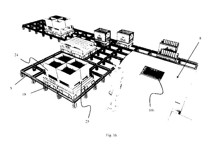
Fig. 16 is a perspective view of an exemplary storage system according to the
invention.
Figs. 17A-17D are perspective views of a first exemplary transport vehicle.
Figs. 18A and 18B are perspective views of a second exemplary transport
vehicle.
Detailed description of the invention
In the following, embodiments of the invention will be discussed in more
detail
with reference to the appended drawings. It should be understood, however,
that the
drawings are not intended to limit the invention to the subject-matter
depicted in the
drawings. Furthermore, even if some of the features are described in relation
to the
system only, it is apparent that they are valid for the related methods as
well, and
vice versa.
An embodiment of a storage grid for an automated storage and retrieval system
according to the invention is shown in figs. 3 and 4 and the same storage grid
featuring a container handling vehicle 300 and a container transfer vehicle 6
is
shown in fig. 5. The number of storage columns of the grid is scaled down to
better
illustrate the features of the storage grid. The major part of the storage
grid is
constructed in the same manner as in the prior art systems shown in figs. 1A
and
2A. That is, the storage grid structure 104 comprises vertical column profiles
102
defining multiple storage columns 105, in which storage containers 106 can be
stored one on top of another in vertical stacks 107. The column profiles 102
are
interconnected at their top ends by top rails 110,111 forming a horizontal
rail grid
108 (hereinafter termed the top rail grid) upon which container handling
vehicles
200,300 may move in two perpendicular directions.
In addition to the storage columns 105, the storage grid structure of the
storage
system comprises multiple transfer columns 119,120 through which storage
containers may be transferred between the top rail grid 108 (i.e. the top
level of the
grid) and a transfer section 2 (or tunnel/passageway) extending within the
storage
grid structure at a level below the top rail grid. The transfer section
extends from an
opening in an external side of the grid structure 104 and below the multiple
transfer
CA 03099204 2020-11-03
WO 2019/238698 PCT/EP2019/065237
22
columns 119,120. In an advantageous embodiment, especially in connection with
large storage grids, the transfer section may extend to a substantially
central
position of the storage grid, and even pass all the way through the storage
grid via a
substantially central section of the storage grid structure 104, to reduce the
distance
a storage handling vehicle 200,300 must travel to reach a transfer column.
The transfer section 2 is defined or constructed by multiple horizontal
ceiling
profiles 3, vertical support profiles 4 and a section of a horizontal rail
grid 5
(hereinafter termed a transfer rail grid). The ceiling profiles 3 providing a
horizontal
support grid 18. The height H of the transfer section 2 may be defined by the
distance between a lowermost surface of a ceiling profile 3 and an upper
surface of
an opposing rail 110', 111' of the transfer rail grid 5, and the width W of
the
transfer section is defined by the distance between an inner surface of two
support
profiles 4 connected to a common ceiling profile 3. The multiple transfer
columns
119,120 are defined by vertical column profiles extending from the top rail
grid to
the ceiling profiles 3. The height H of the transfer section 2 is sufficient
to allow a
container transfer vehicle 6 to travel within the transfer section 2 when
carrying a
storage container.
The ceiling profiles 3, and/or the support grid 18, are supported by the
vertical
support profiles 4 arranged at the periphery of the transfer section 2.
Fig. 5 shows a situation in which a storage container 106 is being transferred
between a container transfer vehicle 6 and a container handling vehicle 300.
The transfer rail grid 5 in the transfer section 2 comprises rails 110',111'
(i.e.
transfer rails), similar to the rails 110,111 (i.e. top rails) of the top rail
grid 108,
upon which a container transfer vehicle 6 (or delivery vehicle) may move in
two
perpendicular directions. The container transfer vehicle 6, see figs. 14A and
14B for
an embodiment of a suitable transfer vehicle, features a wheel base unit 22,
see figs.
15A-15C, having a wheel arrangement. The wheel arrangement comprises a first
set
of wheels 32a enabling movement of the transport vehicle in a first direction
and a
second set of wheels 32b enabling movement of the transport vehicle in a
second
direction perpendicular to the first direction, allowing the vehicle to travel
upon the
transfer rail grid 5. On top of the wheel base unit 22 the container transfer
vehicle 6
features a container carrier 38 for accommodating a storage container to be
transferred. The disclosed container transfer vehicle 6 features a container
carrier 38
in the form of a deep tray, in which a lower portion of a storage container
106 may
be accommodated. However, numerous alternative solutions for suitable
container
carriers are envisaged and the main functional feature of all suitable
containers
carriers is the ability to receive a storage container being lowered on top of
the
container carrier and retain the storage container during movement of the
container
CA 03099204 2020-11-03
WO 2019/238698 PCT/EP2019/065237
23
transfer vehicle upon the transfer rail grid 5. Further, the horizontal
periphery of the
container transfer vehicle 6 is preferably such that each of the multiple
adjacent
transfer columns 119,120 may be used to transfer a storage container 106 to a
respective container transfer vehicle 6 simultaneously. To obtain the latter
function,
the horizontal periphery of the container transfer vehicle 6 fits within the
horizontal
area defined by one of the grid cells 122' of the transfer rail grid 5.
Further, the
transfer rails 110',111' extending in one of the two perpendicular directions
are
dual-track rails, see below, to allow multiple container transfer vehicles to
be
arranged adjacently below the multiple adjacent transfer columns 119,120.
The transfer section 2 has a width W providing room for three separate
transfer
vehicle paths 7, 7', 7" in a longitudinal direction of the transfer section.
By having
three separate transfer vehicle paths, three transfer vehicles 6 may pass each
other at
the same time. To allow this feature, at least the rails 111'extending in the
longitudinal direction of the transfer section are dual-track rails. Suitable
dual-track
rails are disclosed in for example WO 2015/193278 Al and WO 2015/140216 Al.
A dual-track rail 110',111' comprises two parallel tracks. In other words,
three
parallel dual-track rails may provide two parallel transfer vehicle paths. The
rails
110' arranged in a perpendicular direction relative the rails 111' extending
in the
longitudinal direction of the transfer section may be single-track rails or
dual-track
rails. In particular, when the storage grid structure 104 comprises multiple
adjacent
transfer columns 119,120, it may be advantageous that all rails 110',111' in
the
transfer rail grid 5 are dual-track rail as it provides an optimum flexibility
for
movement of the container transfer vehicles 6 to/from the positions below the
transfer columns 119,120. The design of the transfer rails 110',111'and the
wheel
arrangement 32a,32b of the container transfer vehicles 6 allows the vehicles
to
change tracks when needed, i.e. the container transfer vehicle 6 may move in
two
perpendicular directions upon the transfer rail grid 5. The wheel arrangement
may
preferably be similar to the ones described for the prior art container
handling
vehicles 200,300.
Depending on the requirements of the storage system (i.e. the size of the
storage
grid, turnover of storage containers etc.) one or more of the transfer vehicle
paths 7,
7', 7"are arranged below an optional number of transfer columns 119,120. The
grid
columns 112 arranged above the transfer section and not designated as transfer
columns may be used as storage columns 105' (see figs. 6 and 12). This is
achieved
by adding stopper elements 16 (e.g. brackets fastened to the relevant column
profiles) at the lower end of the respective grid columns 102 (the stopper
elements
in the storage columns 105' arranged above the transfer section 2 is not
visible in
the drawings). The stopper elements 16 are designed to support a storage
container
106 being lowered into the respective grid column 112 and prevent it from
entering
the transfer section 2 below. In this manner a minimum of potential storage
space is
CA 03099204 2020-11-03
WO 2019/238698 PCT/EP2019/065237
24
lost from the storage grid structure 104 due to the transfer section 2. The
stopper
elements 16 may also be used to provide an operator passage 17 below a row of
storage columns 105' adjacent to the transfer section 2. In this manner, an
operator
or service person may access a container transfer vehicle 6, for instance in
case of a
failure preventing the vehicle from exiting the transfer section.
The transfer rail grid 5 extends out of the storage grid structure 104 and
depending
on the design and extent of the transfer rail grid 5, the container transfer
vehicles 6
may be used to transfer storage containers 106 between multiple separate
storage
grid structures, transfer containers from a storage grid to a picking/stocking
stations, transfer to dedicated stocking zones, transfer to an assembly line
for
delivery of parts, etc.
A second embodiment of the storage grid 104 for an automated storage and
retrieval
system according to the invention is shown in figs. 7 and 8. In this
embodiment, the
differentiating feature in view of the embodiment discussed above is that the
transfer section 2 is arranged along or adjacent an external side section 12
of the
storage grid 104.
A third embodiment of the storage grid 104 for an automated storage and
retrieval
system according to the invention is shown in figs. 9 and 10. The main
differentiating feature of the third embodiment in view of the embodiments
discussed above is the construction of the support grid 18 allowing the
container
transfer vehicles to exit/enter the transfer section via the longitudinal side
of the
transfer section.
The preferred arrangement and size of the transfer section 2 in any given
storage
system, as well as the positioning of the transfer columns 119,120, will
depend on
the size of the storage grid structure 104, the intended use of the storage
system 1,
the available space in which the storage system is arranged, the shape/layout
of said
space, etc. Independent of the specific positioning of the transfer section 2
within
the storage grid structure, the storage system according to the invention will
provide
a number of advantages in view of the prior art storage systems, as disclosed
throughout the present specification.
A schematic overview of an exemplary layout of an exemplary storage system 1
is
shown in figs. 11 and 12. The exemplary layout illustrates some of the many
advantages of the storage system.
The storage system in fig. 11 comprises three separate storage grid structures
104,
104', 104". Each of the first and the third storage grid structures 104,104"
features
a transfer section 2,2" extending through the whole respective storage grid
CA 03099204 2020-11-03
WO 2019/238698 PCT/EP2019/065237
structure, i.e. the transfer sections extend from a first opening 11 in an
external side
12 of the storage grid to a second opening 13 in an opposite external side
12'. In
this manner, a container transfer vehicle 6 having received or delivered a
storage
container 106 via any of the multiple transfer columns 119,120 may exit the
first 11
5 or the second opening 13 of the transfer section 2 depending on which
pathway to a
selected destination is most efficient.
Each of the transfer sections 2,2',2" features three transfer vehicle paths 7,
7', 7",
see fig. 9. The first vehicle path 7 is arranged below multiple adjacent
transfer
10 columns 119,120, through which storage containers 106 may be transferred
between
the top rail grid 108 and a container transfer vehicle 6. The second and third
vehicle
paths 7',7" are arranged below multiple storage columns 105' and are
predominantly used by the container transfer vehicles 6 to travel within the
transfer
section to or from a transfer column 119,120. The transfer section 2' in the
second
15 storage grid 104' does not extend all the way through the storage grid,
and a
container transfer vehicle 6 will always enter and exit the transfer section
via the
first opening.
The transfer grid 5 interconnects the transfer columns 119,120 of the first
storage
20 grid 104 with transfer columns 119,120 of the second and third storage
grid 104',
104", with rail loops/circuits 14 (that may for instance be arranged at a
picking/stocking station, see fig. 13), with a multi-use transfer grid area 15
and any
other destination to which the transfer of a storage container is desired. The
multi-
use transfer grid area 15 may for instance be used for stocking large amounts
of new
25 items to the storage grid, as temporary parking for transfer vehicles
carrying storage
containers comprising high-demand items, as a loading area for storage
containers
to enter the storage grids or may be arranged at a station for loading off
pallets
and/or packaging boxes with items picked from the storage system. To improve
the
efficiency of transporting goods/items between a picking/stocking station and
the
multi-use transfer grid area 15, a dedicated transport vehicle may
advantageously be
used, see description below of the embodiments shown in figs. 16-18.
Use of an area or section of the transfer grid 5 to accommodate container
transfer
vehicles 6 carrying storage containers 106 comprising high-demand items, i.e.
a
parking section of the transfer grid, provides for a highly efficient method
of
retrieving items that have a very high picking rate, i.e. that have a
particularly high
turnover. In prior art systems such high turnover items entail that the
specific
storage container(s) in which these items are stored is transferred back and
forth
between a storage column 105 and a picking/stocking station more or less
continuously. In the inventive storage system, items having a particularly
high
turnover may permanently (or at least intermediately) be stored in a storage
container arranged on a transfer vehicle 6. In this manner, high turnover
items may
CA 03099204 2020-11-03
WO 2019/238698 PCT/EP2019/065237
26
be accessed in a very short time, crowding at the transfer columns are further
minimized and unnecessary use of the container handling vehicles 200,300 are
avoided.
The schematic overview in fig. 12 shows details of the first storage grid 104
in fig.
11 but may also illustrate an alternative layout of a storage system
comprising a
single storage grid 104.
Fig. 13 discloses an embodiment of an inventive storage system having a layout
substantially as shown in fig. 12. The storage system features two
picking/stocking
stations 8, wherein each is arranged such that a container transfer vehicle 6
may
pass beneath a container access opening 9 arranged in the picking/stocking
station
while moving on the transfer rail grid 5. In other words, the picking/stocking
stations 8 are arranged such that a container transfer vehicle 6 may pass
through the
picking/stocking station via rail loops 14 as shown in figs. 11 and 12. Thus,
a
storage container 106 containing an item to be picked (or a storage container
into
which an item is to be stocked) is first retrieved by a container handling
vehicle
200,300 arranged on the top rail grid 108, lowered to a container transfer
vehicle 6
positioned inside the transfer section 2 beneath a suitable transfer column
119,120,
and transported by the container transfer vehicle 6 to a picking/stocking
station 8,
wherein the transfer vehicle stops at a position beneath the container access
opening
9 to allow an operator to pick the item.
The storage system 1 shown in figs. 11 and 12, features three laterally
separated
storage grid structures 104, 104', 104" arranged at the same level. However,
it is
also envisioned that the storage system may comprise storage grid structures
separated in a vertical direction, e.g. stacked on top of each other. When
separated
in the vertical direction, the transfer rail grid of the storage system may
for instance
comprise a container transfer vehicle lift for lifting a container transfer
vehicle
between separate levels of the transfer rail grid, such that a container
transfer
vehicle may access all areas of the transfer grid.
In the disclosed embodiments, the transfer section 2 comprises a section of
the
transfer rail grid 5 featuring three parallel vehicle paths 7,7',7" allowing
three
transfer vehicles 6 to pass each other at the same time. However, many of the
advantages of the present inventive storage system may also be obtained by use
of a
transfer section 2 comprising at least one vehicle path provided the track is
arranged
below at least one transfer column 119,120.
In the disclosed embodiments, the transfer rails 110',111' of the transfer
rail grid 5
are dual-track rails identical to the rails 110,111 of the top rail grid. This
feature is
advantageous in a cost perspective since the number of different parts used in
CA 03099204 2020-11-03
WO 2019/238698 PCT/EP2019/065237
27
constructing the storage grid structure 104 is minimized. Further, it allows
for the
use of transfer vehicles 6 having a wheel arrangement similar to the one used
in the
container handling vehicles 200,300, a feature which significantly simplifies
the
overall system cost. However, the main advantages of the inventive storage
system
and storage grid structure, e.g. a highly flexible and efficient transfer of
storage
containers in and out of the storage grid, as well as the avoidance of single
point of
failures disrupting the operation of the storage system, may also be obtained
by
embodiments of the invention, wherein the transfer rails of the transfer rail
grid 5
are different from the rails of the top rail grid 108. An important feature
for
avoiding a single point of failure is that the container transfer vehicles may
pass
each other and move in two perpendicular directions upon at least the section
of the
transfer rail grid arranged in the transfer section. This feature allows the
container
transfer vehicles to pass around for instance a non-functioning container
transfer
vehicle which would otherwise have caused an interruption of the storage
system
operation. The presence of multiple transfer columns may further minimize any
risk
of a single point of failure disrupting the operation of the storage system.
It is noted that the dimensions of the grid cells 122 (see prior art system in
figs. lA
and 2A and the relevant prior art description) of the top rail grid 108 are
preferably
similar or identical to the dimensions of the grid cells 122' (see fig. 10) of
the
transfer rail grid 5. Having the grid cells of similar dimensions allows for
an
optimum use of the inventive storage system by allowing adjacent transfer
columns
to be used simultaneously.
Although the use of dual-track rails 110',111' in at least one direction of
the
transfer rail grid 5 provides several advantages with regards to for instance
space
efficiency by allowing container transfer vehicles 6 to pass each other at
adjacent
grid cells 122', an advantageous storage system may also be obtained by having
a
transfer grid comprising only single-track rails. Use of only single-track
rails
would, however, require a larger transfer grid to allow container transfer
vehicles 6
passing each other, as compared to dual-track rails, since such a grid would
not
allow the container transfer vehicles 6 to pass each other on adjacent grid
cells
122'. For instance, the dual-track transfer rails 110',111' of the transfer
grid 5
disclosed in fig. 3 and 5 could be replaced by single-track rails. In that
case, two
container transfer vehicles 6 would still be able to pass each other upon the
transfer
grid 5, for instance by having one of the container transfer vehicles
travelling on
vehicle path 7 and the other on vehicle path 7".
The automated storage and retrieval system shown in figs. 3-13 is more
effective
than prior art systems by avoiding or at least reducing congestion of
container
handling vehicles at the transfer columns. Further advantages of the storage
system
include increased availability of a transfer column for container handling
vehicles
CA 03099204 2020-11-03
WO 2019/238698 PCT/EP2019/065237
28
operating on top of the storage grid and reduced vulnerability to single point
of
failure events that may disrupt the operation of the storage system. The
storage
system is also highly flexible in that the storage container transfer
capacity, as well
as the purpose/function of the storage container handling system, can easily
be
increased or modified after installation.
An advantageous transport system for obtaining an efficient transport of items
between the picking/supply station 8 and an unloading/loading assembly 23 is
shown in fig. 16. The exemplary unloading/loading assembly 23 is shown
schematically in fig. 11 and features a conveyor for transporting boxes or
pallets to
and/or from the multi-use transfer grid area 15.
In prior art systems, items to be retrieved from the storage grid 104 are
picked from
the relevant storage containers 106 by an operator at a picking/supply station
and
transferred to packaging boxes 24. The packaging boxes 24 are often arranged
on a
pallet 25, which the operator subsequently transports to the unloading/loading
assembly 23. At the unloading/loading assembly 23, the packaging boxes
24/pallet
are for instance loaded onto a truck for transport to customers, shops etc.
The
efficiency of the process of picking items, packing them in boxes and
transferring
20 them to an unloading/loading station is not optimized. In particular,
the process
requires that the operator use valuable time in transporting the packaging
boxes/pallet from the picking/supply station to the unloading/loading
assembly.
To provide an efficient transport of items between the picking/supply station
8 and
25 an unloading/loading assembly 23, the disclosed transport system
features a
transport vehicle 19 running on a transfer grid 5 extending between the
picking/supply station 8 and the unloading/loading assembly 23. The transfer
grid 5
of the transport system may comprise any of the features described above for
the
transfer grids 5 shown in figs. 3-13.
The transport vehicles shown in fig. 16, as well as figs. 17A-17D, features
four
wheel base units 22 providing a wheel arrangement having a first set of wheels
32a
enabling movement of the transport vehicle in a first direction and a second
set of
wheels 32b enabling movement of the transport vehicle in a second direction
perpendicular to the first direction upon the transfer grid 5.
A carrier platform 20 having a conveyor system 21 may be arranged on top of
the
wheel base units 22, as shown. The carrier platform 20 may be sized to support
four
packaging boxes 24 and/or a pallet 25, i.e. the area of the carrier platform
is
substantially equal to the footprint of four storage containers arranged two
by two in
such an embodiment. In the disclosed storage system, the storage containers
may
preferably have a width of 449 mm and a length of 649 mm. The preferred
CA 03099204 2020-11-03
WO 2019/238698 PCT/EP2019/065237
29
dimensions entail that a carrier platform having an area substantially equal
to the
footprint of four storage containers arranged two by two may accommodate a EUR
1 pallet.
In the exemplary embodiment, the conveyor system 21 is made up of multiple
rollers 27, but other conveyor systems, such as belt or chain conveyors, may
also be
used. The conveyor system 21 is advantageous in that it allows the packaging
boxes
and/or pallet arranged on the carrier platform 20 to be moved off the
transport
vehicle onto the conveyor of the unloading/loading assembly 23. However, in
alternative embodiments of the transport vehicle, the carrier platform may
also be
without a conveyor system provided the unloading/loading assembly features a
lift
device (e.g. a pallet jack) arranged to remove packaging boxes 24 or a pallet
25
from the carrier platform.
The wheel base units 22 of the exemplary transport vehicle 19 are similar to
the
wheel base units 22, see figs. 15A-15C, of the transfer vehicles 6 described
above.
Each wheel base unit 22 features a first set of wheels 32a enabling movement
of the
wheel base unit in a first direction and a second set of wheels 32b enabling
movement of the wheel base unit in a second direction perpendicular to the
first
direction upon the transfer grid 5. In the exemplary wheel base unit, the
second set
of wheels 32b is connected to an arrangement for moving the second set of
wheels
in a vertical direction relative to the first set of wheels. The arrangement
features
wheel connecting plates 28 on opposite sides of the wheel base unit 22 and a
displacement arm assembly 29 for moving the wheel connecting plates 28, and
consequently the second set of wheels, in a vertical direction. Each set of
wheels
32a,32b of the wheel base unit comprises two pairs of wheels arranged on
opposite
sides of the wheel base unit.
In the exemplary embodiment, the wheel base units 22 are adjacently connected
by
multiple connecting profiles 26 and the carrier platform 20 connected to the
connecting profiles. Alternative solutions for connecting the wheel base units
are
also possible and envisaged herein.
An advantage of having a transport vehicle 19 made up of multiple wheel base
units
22 is that a desired size and transport capacity may easily be achieved by
varying
the number of wheel base units. A further exemplary transport vehicle 19'
having
two wheel base units is shown in figs. 18A and 18B.
A further advantage of having the transport vehicle 19 made up of multiple
wheel
base units 22 is that the transport vehicle is not only supported by the
wheels along
its periphery but also supported and driven by wheels along a centreline of
the
vehicle. This feature provides a high capacity transport vehicle 19 without
requiring
CA 03099204 2020-11-03
WO 2019/238698 PCT/EP2019/065237
any further reinforcement of the wheels or drive motors to compensate for the
increased load.
The transport system in fig. 16 is disclosed with a picking/supply station 8
and
5 transfer vehicles 6 for transferring storage containers between the
storage grid and
the picking/supply station. However, the transport system is not dependent on
the
transfer vehicles 6 and a transfer section 2 as discussed in connection with
figs. 3-
13 and may alternatively comprise a prior art picking/supply station arranged
to
receive storage containers 106 directly via a transfer column 119,120 without
the
10 use of a transfer vehicle 6. Exemplary prior art picking/supply stations
suitable for
the present transport system are disclosed in for instance WO 2012/026824 Al.
In
alternative embodiments, wherein a storage system comprising the transport
system
does not feature container transfer vehicles 6, the multi-use transfer grid
area 15
may simply be termed a transfer grid area as it is not used for the various
operations
15 requiring the container transfer vehicles.
In addition to providing a highly efficient transport of items from the
picking/supply station to the unloading/loading assembly, the disclosed
transport
system is also highly efficient for restocking the storage system with new
items
20 brought to the storage system facility on pallets and/or in packaging
boxes. The
transport system may advantageously also be used for loading new storage
containers into the storage grid structure and retrieving used storage
containers (e.g.
worn out storage containers to be replaced) from the storage grid structure.
25 The disclosed storage system provides a highly flexible container
transfer and
handling solution. Not only does the present solution facilitate the transfer
of
storage containers to or from the storage grid structure of an automated
storage
system, but it also provides for a simple and efficient solution for transfer
of storage
containers between separate storage grids, as well as between a storage grid
and any
30 location for further handling or processing of the storage containers
and/or their
content. The container handling capacity of the storage system may easily be
extended, and/or the function repurposed to accommodate any future changes in
the
requirements of a completed storage system.
40
CA 03099204 2020-11-03
WO 2019/238698
PCT/EP2019/065237
31
Reference numerals:
1 Storage system
2 Transfer section
3 Horizontal ceiling profile
4 Vertical support profile
Transfer rail grid
6 Container transfer vehicle
7 Transfer vehicle path
8 Picking/stocking station
9 Container access opening
Rail circuit
11 First opening (in an external side of a storage grid)
12 An external side of a storage grid
13 Second opening (in an external side of a storage grid)
14 Rail circuit
Multi-use transfer grid area
16 Stopper element
17 Operator access passage
18 Support grid
19 Transport vehicle
Carrier platform
21 Conveyor assembly
22 Wheel base unit
23 Unloading/loading assembly
24 Packaging box
Pallet
26 Connecting profile/beam
27 Rollers
28 Wheel connecting plate
29 Displacement arm assembly
32a,32b Wheel arrangement of wheel base unit
32a First set of wheels of wheel base unit
32b Second set of wheels of wheel base unit
38 Container carrier
100 Framework structure
102 Upright members of framework structure, i.e. vertical column
profiles
103 Horizontal members of framework structure
104 Storage grid, storage grid structure
105 Storage column
105' Storage column arranged above a transfer section
106 Storage container
CA 03099204 2020-11-03
WO 2019/238698 PCT/EP2019/065237
32
107 Stack
108 Top rail grid, rail system
110 First set of parallel rails in first direction (X), top rails
111 Second set of parallel rails in second direction (Y), top rails
110' Transfer rails, in a first direction of a transfer rail grid
111' Transfer rails, in a second direction, perpendicular to the first
direction,
of a transfer rail grid
112 Grid column
115 Grid opening
119 Transfer column,
120 Transfer column
122 Grid cell
200 Prior art container handling vehicle
201,301 Wheel arrangement
300 Second container handling vehicle
X First direction
Y Second direction
Z Third direction
10
20