Note : Les descriptions sont présentées dans la langue officielle dans laquelle elles ont été soumises.
CA 03118751 2021-05-04
WO 2020/112755
PCT/US2019/063227
DURA ELEVATING AND CUTTING APPARATUS
CROSS REFERENCE TO RELATED APPLICATIONS
[0001] This is a non-provisional application that claims benefit to
U.S.
provisional application serial no. 62/773,008 filed on November 29, 2018,
which is
herein incorporated by reference in its entirety.
FIELD
[0002] The present disclosure generally relates to surgical devices,
and
in particular, to a surgical apparatus for lifting and incising dura mater
during
neurosurgery.
BACKGROUND
[0003] Neurosurgery often requires one or more incisions into the
dura
mater, a thin membrane encapsulating the brain underneath the skull. A tiny
nick is
created in the dura mater in order for a surgeon to insert a dural elevator
and lift the
dura mater away from the brain. This step allows a surgeon to hold the dura
taut and
away from the brain while cutting the dura and otherwise working within the
space.
Conventional technologies perform this task using separate tools to lift the
dura and
cut the dura, thereby requiring multiple hands to pass and hold very sharp
blades
while working in a small and delicate surgical space.
[0004] It is with these observations in mind, among others, that
various
aspects of the present disclosure were conceived and developed.
BRIEF DESCRIPTION OF THE DRAWINGS
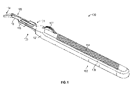
[0005] FIG. 1 is a perspective view of a first embodiment of a dura
elevating and cutting apparatus showing a scalpel housing and a shield in an
"engaged" position;
[0006] FIG. 2 is a perspective view of the present apparatus of FIG.
1
showing the shield in a "recessed" position;
[0007] FIG. 3 is a perspective view of the present apparatus of FIG.
1
showing the shield between the engaged and recessed position;
[0008] FIG. 4 is a side view of the scalpel housing of FIG. 1 showing
a
shield storage slot for engagement with the shield;
[0009] FIG. 5 is a top view of the scalpel housing of FIG. 4;
1
CA 03118751 2021-05-04
WO 2020/112755
PCT/US2019/063227
[0010] FIG. 6 is a bottom view of the scalpel housing of FIG. 4;
[0011] FIG. 7 is a top perspective view of the scalpel housing of
FIG. 4;
[0012] FIG. 8 is a perspective view of the shield of FIG. 1;
[0013] FIG. 9 is a top view of the shield of FIG. 8;
[0014] FIG. 10 is a side view of the shield of FIG. 8 showing a blade
shield and tip lock for engagement with the scalpel housing;
[0015] FIG. 11 is an opposite side view of the shield of FIG. 8;
[0016] FIG. 12A is a top view of the shield of FIG. 9 showing a post
of a
rotator receptacle partially engaged within an longitudinal portion of the
shield;
[0017] FIG. 12B is a top view of the shield and post of FIG. 12A
showing the post engaged within a circular portion of the shield;
[0018] FIG. 12C is a top view of the shield and post of FIG. 12A
showing the post engaged within a latitudinal portion of the shield;
[0019] FIG. 13 is a side view of the apparatus of FIG. 2 showing the
shield engaged inside the shield storage slot;
[0020] FIG. 14 is a top view of the apparatus of FIG. 2;
[0021] FIG. 15 is an opposite side view of the apparatus of FIG. 2;
[0022] FIG. 16 is a top view of the apparatus of FIG. 3;
[0023] FIG. 17 is a top view of the apparatus of FIG. 1 showing the
blade shield engaged with a head portion of the scalpel housing;
[0024] FIG. 18 is a side view of the apparatus of FIG. 1 showing the
blade shield engaged with the head portion of the scalpel housing;
[0025] FIG. 19 is an opposite side view of the apparatus of FIG. 1;
[0026] FIG. 20 is a bottom view of the apparatus of FIG. 1;
[0027] FIG. 21 is a side view of a second embodiment of a dura
elevating and cutting apparatus including a scalpel housing and a shield shown
in an
engaged position;
[0028] FIG. 22 is a perspective view of the shield of the apparatus
of
FIG. 21;
[0029] FIG. 23 is a top view of the shield of FIG. 21;
[0030] FIG. 24 is a side view of the shield of FIG. 21;
[0031] FIG. 25 is a side view of the scalpel housing of FIG. 21;
[0032] FIG. 26 is an opposite side view of the apparatus of FIG. 21;
2
CA 03118751 2021-05-04
WO 2020/112755
PCT/US2019/063227
[0033] FIG. 27 is a side view of the apparatus of FIG. 21 shown in a
recessed position;
[0034] FIG. 28 is a perspective view of a third embodiment of a dura
elevating and cutting apparatus including two heads;
[0035] FIG. 29A is a top view of a first head portion of the
apparatus of
FIG. 28;
[0036] FIG. 29B is a top view of a second head portion of the
apparatus of FIG. 28; and
[0037] FIG. 30 is a side view of a head portion of the apparatus of
FIG.
28 featuring a curved neck.
[0038] Corresponding reference characters indicate corresponding
elements among the view of the drawings. The headings used in the figures do
not
limit the scope of the claims.
DETAILED DESCRIPTION
[0039] Various embodiments of a dural elevating and cutting apparatus
are disclosed herein. In some embodiments, the dural elevating and cutting
apparatus includes a scalpel housing in engagement with a shield by a rotator
defined at a proximal end of the shield. The scalpel housing includes a blade
receptacle defined at a head portion of the scalpel housing for receiving and
securing a standard scalpel blade. The shield further includes an elevator at
a distal
end of the shield configured for lifting dural tissue. The shield is operable
for rotation
between a recessed position in which the shield is disposed within the scalpel
housing and an engaged position in which the shield covers the scalpel blade
and is
otherwise engaged with the head portion of the scalpel housing, thereby
allowing a
surgeon to use the scalpel blade installed within the scalpel housing to cut
into tissue
with the shield recessed or to use the shield to cover the blade and lift the
dura
mater to widen an incision in the dura mater. The surgeon can also cut the
dura
mater while in the engaged position by orienting the apparatus such that the
dura
mater is positioned between a cutting edge of the scalpel blade and the
elevator and
driving the apparatus along a direction the surgeon intends to cut. Referring
to the
drawings, embodiments of a dural elevating and cutting apparatus are
illustrated and
generally indicated as 100 in FIGS. 1-20, 200 in FIGS. 21-27, and 300 in FIGS.
28-
30.
3
CA 03118751 2021-05-04
WO 2020/112755
PCT/US2019/063227
[0040] The dural elevating and cutting apparatus 100, shown in FIGS.
1-3 and 12-20 and referred to herein as "the apparatus", includes a scalpel
housing
102 having a handle portion 108 configured for gripping by the surgeon and a
head
portion 109 configured to receive a scalpel blade 10 and a shield 101. The
shield
101 defines a rotator 107 and a stem 103, where the stem 103 includes an
elevator
104 and a blade shield 105 configured for elevating the dura mater and
covering at
least part of the scalpel blade 10. The rotator 107 engages with a rotator
receptacle
117 defined by the head portion 109 of the scalpel housing 102 such that the
shield
101 is operable for clockwise or counterclockwise rotation between a recessed
position shown in FIG. 2 and an engaged position shown in FIG. 1. While in the
recessed position, the stem 103 of the shield 101 engages with a shield
storage slot
110 of the scalpel housing 102. Conversely, while in the engaged position, the
blade
shield 105 defined by the stem 103 engages with the head portion 109 of the
scalpel
housing 102 and the elevator 104 is positioned distal to the head portion 109.
[0041] As noted above, the scalpel housing 102 shown in FIGS. 4-7
includes the handle portion 108 and the head portion 109, wherein the head
portion
109 is configured to receive the scalpel blade 10 and the shield 101. The head
portion 109 defines an elongated tip 116 and a blade receptacle 122 configured
for
engagement with the scalpel blade 10 at a distal end 115 of the scalpel
housing 102.
An upper angled surface 120 and a lower surface 121 are also defined along the
head portion 109. In addition, the head portion 109 further defines a rotator
receptacle 117 located between the handle 108 and the upper angled surface
120,
wherein the rotator receptacle 117 is configured for engagement with the
rotator 107
of the shield 101. The handle 108 includes a gripping portion 114 and a shield
storage slot 110 defined along a handle surface 113 of the handle 108. The
shield
storage slot 110 defines a channel portion 111 and a tip slot 112 for
receiving the
respective stem 103 and elevator 104 of the shield 101 when in the recessed
position. In some embodiments, the tip 116 and blade receptacle 122 defined at
the
distal end 115 of the scalpel housing 102 are configured for engagement with
most
standard disposable scalpel blades 10. In some embodiments such as the
embodiment of FIG. 4, the rotator receptacle 117 includes a horizontal slot
118
defined through the head portion 109. A post 119 is formed within the
horizontal slot
118 of the rotator receptacle 117 for engagement with the rotator 107 of the
shield
101, a mechanism which will be described in greater detail below.
4
CA 03118751 2021-05-04
WO 2020/112755
PCT/US2019/063227
[0042] FIGS. 8-11 illustrate the shield 101 of the apparatus 100
including the stem 103, the rotator 107 defined at a proximal end 134 of the
stem
103, and the elevator defined at a distal end 135 of the stem 103.
Furthermore, the
blade shield 105 and the tip lock 106 are defined along a midsection 136 of
the stem
103 for engagement with the scalpel blade 10 and tip 116 of the scalpel
housing 102.
The rotator 107 is a circular-shaped structure defined at the proximal end 134
of the
stem 103 and configured for engagement with the rotator receptacle 117 of the
scalpel housing 102. The rotator 107 further defines a pathway 130, shown in
FIGS.
9 and 12A-C, where the pathway 130 forms a longitudinal portion 131 in
communication with a circular portion 132 and a latitudinal portion 133, where
the
opening of the longitudinal portion 131 is defined along the peripheral edge
141 of
the rotator 107. This configuration of the longitudinal portion 131, circular
portion 132
and latitudinal portion 133 allows for insertion of the rotator 107 into the
horizontal
slot 118 of the rotator receptacle 117 such that the longitudinal portion 131
receives
the post 119 (shown in FIG. 12A) and the rotator 107 can be moved relative to
the
post 119 such that the post 119 is moved into the circular portion 132, as
shown in
FIG. 12B. In this position, the rotator 107 may be manually rotated in a
clockwise or
counterclockwise direction A such that the stem 103 of the shield 101 is
engaged
within the shield storage slot 110 of the scalpel housing 102 in the recessed
position
of FIG. 2. The rotator 107 may also be manually rotated in an opposite
counterclockwise or clockwise direction B such that the blade shield 105 of
the
shield 101 is oriented towards the head portion 109 of the scalpel housing 102
in the
engaged position of FIG. 1. While the blade shield 105 is oriented towards the
head
portion 109, the shield 101 may then be driven in a lateral direction relative
to the
scalpel housing 102 such that the post 119 slides out of the circular portion
132 and
then engages the latitudinal portion 133, as shown in FIG. 12C.
[0043] The blade shield 105 of the shield 101 further defines an
indentation 125 along a lateral side 137 of the stem 103 for engagement with
the
scalpel blade 10 when in the engaged position. When driving the shield 101 in
the
lateral direction such that the post 119 engages the latitudinal portion 133
of the
pathway 130, the indentation 125 defined along the stem 103 also engages with
the
scalpel blade 10 as shown in FIG. 20. The blade shield 105 further defines a
brim
126 directly above the indentation 125 in a direction of elongation of the
shield 101
for engagement with the upper angled surface 120 while in the engaged
position, as
CA 03118751 2021-05-04
WO 2020/112755
PCT/US2019/063227
shown in FIG. 17. A tab 142 is defined at a proximal end of the brim 126 to
provide a
surface for a surgeon to place their finger over the blade receptacle 122 for
added
stability in the hand. In some embodiments, the tab 142 may include textured
grooves (not shown) along an upper surface of the tab 142 for haptic feedback.
The
blade shield 105 also defines a tip lock 106 for engagement with the tip 116
of the
head portion 109 of the scalpel housing 102. In some embodiments, the tip lock
106
includes an elongated semicircular recess 128 configured for engagement with
the
tip 116. As shown in FIGS. 10, 11, and 18, some embodiments of the tip lock
106
include a tip lock wall 127 defined along a lateral edge 139 of the tip lock
106 for
added stability.
[0044] The shield 101 further includes the elevator 104 defined at
the
distal end 135 of the stem 103. When in the engaged position, the elevator 104
extends beyond the blade 10 for lifting the dura mater away from the brain.
The
elevator 104 terminates at a point 123, where the point 123 may include a
dulled
edge so as to gently lift the dura mater without puncturing or otherwise
unintentionally damaging tissue. In some embodiments, the elevator 104
includes an
elevator ramp 124 to further shield the brain tissue and dura mater from the
blade
10. As shown in FIGS. 10 and 11, the elevator 104 creates an obtuse angle
relative to the direction of elongation of the shield 102. The obtuse angle p
formed
by the elevator 104 in some embodiments may be 1100, but the obtuse angle p
may
vary depending on the surgeon's preference.
[0045] FIGS. 1 and 17-20 illustrate the apparatus 100 having the
blade
engaged within the indentation 125 of the blade shield 105 and the elevator
104
located in distal relation to the tip 116 when in the engaged position.
Conversely,
FIGS. 2 and 13-15 illustrate the apparatus 100 having the shield 101 engaged
within
the shield storage slot 110 when in the recessed position with the blade 10
exposed
for contact with tissue. As discussed above, the shield 101 is operable for
rotation
between the engaged and recessed positions. FIGS. 3 and 16 illustrate the
apparatus 100 between the engaged and recessed positions having the rotator
107
engaged within the rotator receptacle 117 and with the distal end 135 of the
shield
101 extending laterally along a direction of elongation of the scalpel housing
102,
rather than engaged within the shield storage slot 110 as in the recessed
position or
engaged with the head portion 109 of the scalpel housing 102 as in the engaged
position.
6
CA 03118751 2021-05-04
WO 2020/112755
PCT/US2019/063227
[0046] In one method of use of the apparatus 100, a preliminary
incision is made using the blade 10 while the apparatus 100 is in the recessed
position. The shield 101 is then moved into the engaged position such that the
elevator 104 extends distally to the tip 116 of the scalpel housing 102. The
elevator
104 is then inserted into the preliminary incision and may be used to lift the
dura
mater away from the brain. To expose the blade 10 for cutting purposes, the
shield
101 can be rotated away from the engaged position and back to the recessed
position such that the shield 101 is seated within the shield storage slot 110
of the
scalpel housing 102. The surgeon can also cut the dura mater while in the
engaged
position by orienting the apparatus 100 such that the dura mater is positioned
between a cutting edge of the scalpel blade 10 and the ramp 124 of the
elevator 104
and driving the apparatus 100 along a direction the surgeon intends to cut.
[0047] FIGS. 25-27 illustrate a second embodiment of the dural
elevating and cutting apparatus designated 200, having a scalpel housing 202
and
including a handle portion 208 and a head portion 209 configured to receive a
scalpel blade 20 and a shield 201. The shield 201 defines a rotator 207 and a
stem
203, where the stem 203 includes an elevator 204 and a blade shield 205 for
elevating the dura mater and covering at least part of the scalpel blade 20.
The
rotator 207 engages with a rotator receptacle 217 defined by the head portion
209 of
the scalpel housing 202 such that the shield 201 is operable for clockwise or
counterclockwise rotation between a recessed position shown in FIG. 27 and an
engaged position shown in FIG. 25. While in the recessed position, the stem
203 of
the shield 201 engages with a shield storage slot 210 of the scalpel housing
202.
Conversely, while in the engaged position, the blade shield 205 defined by the
stem
203 engages with the head portion 209 of the scalpel housing 202 and the
elevator
204 is located distal to the head portion 209.
[0048] As noted above, the scalpel housing 202 shown in FIG. 21
includes the handle portion 208 and the head portion 209, where the head
portion
209 is configured to receive the scalpel blade 20 and the shield 201. The head
portion 209 defines an elongated tip 216 and a blade receptacle 222 configured
for
engagement with the scalpel blade 20 at a distal end 215 of the scalpel
housing 202.
An upper angled surface 220 and a lower surface 221 are also defined along the
head portion 209 and the upper angled surface 220 is configured for engagement
with the shield 201. Lastly, the head portion 209 further defines a rotator
receptacle
7
CA 03118751 2021-05-04
WO 2020/112755
PCT/US2019/063227
217 located between the handle 208 and the upper angled surface 220, wherein
the
rotator receptacle 217 is configured for engagement with the rotator 207 of
the shield
201. The handle 208 includes a gripping portion 214 and a shield storage slot
210
defined along a handle surface 213 of the handle 208. The shield storage slot
210
defines a channel portion 211 and a tip slot 212 for receiving the respective
stem
203 and elevator 204 of the shield 201 when in the recessed position. In some
embodiments, the tip 216 and blade receptacle 222 defined at the distal end
215 of
the scalpel housing 202 are configured for engagement with most standard
disposable scalpel blades 20. In some embodiments such as the embodiment of
FIG. 21, the rotator receptacle 217 includes a horizontal slot 218 defined
through the
head portion 209. A well 219 is formed within the horizontal slot 218 of the
rotator
receptacle 217 for engagement with the rotator 207 of the shield 201, a
mechanism
which will be described in greater detail below.
[0049] Similar to the embodiment of the apparatus 100, FIGS. 22-24
illustrate the shield 201 of the apparatus 200 including the stem 203, the
rotator 207
defined at a proximal end 234 of the stem 203 and the elevator defined at a
distal
end 235 of the stem 203. Furthermore, the blade shield 205 and the tip lock
206 are
defined along a midsection 236 of the stem 203 for engagement with the scalpel
blade 20 and tip 216 of the scalpel housing 202. The rotator 207 is a circular-
shaped
structure defined at the proximal end 234 of the stem 203 and configured for
engagement with the rotator receptacle 217 of the scalpel housing 202. The
rotator
207 further defines a rotator post 230 protruding from a face 207A of the
rotator 207.
The rotator 207 is inserted into the horizontal slot 218 of the rotator
receptacle 217
such that the well 219 receives the rotator post 230 and the rotator 207 can
be
rotated within the rotator post 230. In this position, the rotator 207 may be
manually
rotated in a clockwise or counterclockwise direction A such that the stem 203
of the
shield 201 is engaged within the shield storage slot 210 of the scalpel
housing 202 in
the recessed position of FIG. 27. The rotator 207 may also be manually rotated
in an
opposite counterclockwise or clockwise direction B such that the blade shield
205 of
the shield 201 is oriented towards the head portion 209 of the scalpel housing
202 in
the engaged position of FIGS. 25-26.
[0050] The blade shield 205 of the shield 201 further defines an
indentation 225 along a lateral side 237 of the stem 203 for engagement with
the
scalpel blade 20 when in the engaged position. When in the engaged position,
the
8
CA 03118751 2021-05-04
WO 2020/112755
PCT/US2019/063227
indentation 225 defined along the stem 203 also engages with the scalpel blade
20
as shown in FIG. 20. The blade shield 205 further defines a brim 226 directly
above
the indentation 225 along a direction of elongation of the shield 201 for
engagement
with the upper angled surface 220 while in the engaged position, as shown in
FIGS.
22, 25 and 26. Similar to the previous embodiment of the apparatus 100, a tab
242 is
defined at a proximal end of the brim 226 to provide a surface for a surgeon
to place
their finger over the blade receptacle 222 for added stability within the
hand. In some
embodiments, the tab 242 may include textured grooves (not shown) along an
upper
surface of the tab 242 for haptic feedback. The blade shield 205 also defines
a tip
lock 206 for engagement with the tip 216 of the head portion 209 of the
scalpel
housing 202. In some embodiments, the tip lock 206 includes an elongated
semicircular recess 228 configured for engagement with the tip 216. Unlike the
tip
lock 106 of the previous embodiment of the apparatus 100, some embodiments
such
as the embodiment shown in FIGS. 22-24 do not include a tip lock wall.
[0051] The shield 201 further includes the elevator 204 defined at
the
distal end 235 of the stem 203. When in the engaged position, the elevator 204
extends beyond the blade 20 for lifting the dura mater away from the brain.
The
elevator 204 terminates at a point 223, where the point 223 may include a
dulled
edge so as to gently lift the dura mater without puncturing or otherwise
unintentionally damaging tissue. As shown in FIG. 24, the elevator 204 creates
an
obtuse angle p relative to the direction of elongation of the shield 202. The
obtuse
angle p may be 1100, but the obtuse angle p may vary between embodiments
depending on the surgeon's preference.
[0052] FIGS. 25 and 26 illustrate the apparatus 200 having the blade
20 engaged within the indentation 225 of the blade shield 205 and the elevator
204
located in distal relation to the tip 216 when in the engaged position.
Conversely,
FIG. 27 illustrates the apparatus 200 having the shield 201 engaged within the
shield
storage slot 210 when in the recessed position with the blade 20 exposed for
contact
with tissue. As discussed above, the shield 201 is operable for rotation
between the
engaged and recessed positions. In one method of use of the apparatus 200, a
preliminary incision is made using the blade 20 while the apparatus 200 is in
the
recessed position. The shield 201 is then moved into the engaged position such
that
the elevator 204 extends distal to the tip 216 of the scalpel housing 202. The
elevator 204 is then inserted into the preliminary incision and may be used to
lift the
9
CA 03118751 2021-05-04
WO 2020/112755
PCT/US2019/063227
dura mater away from the brain. To expose the blade 20 for cutting purposes,
the
shield 201 can be rotated away from the engaged position and back to the
recessed
position such that the shield 201 is seated within the shield storage slot 210
of the
scalpel housing 202. The surgeon can also cut the dura mater while in the
engaged
position by orienting the apparatus 200 such that the dura mater is positioned
between a cutting edge of the scalpel blade 20 and the elevator 204 and
driving the
apparatus 200 along a direction the surgeon intends to cut.
[0053] Referring to FIGS. 28-30 a third embodiment of a dural
elevating
and cutting apparatus, designated 300, may include an elongated body 301
comprising a handle 302 and each end of the elongated body 301 terminating in
a
head portion 303. Each head portion 303A (or 303B) includes an elevator 305A
(or
305B) and a blade shield 306A (or 306B), both extending laterally from a
direction of
elongation of the elongated body 301. In some embodiments, a blade receptacle
307A (or 307B) is formed between the elevator 305A (or 305B) and the blade
shield
306A (or 306B) and is configured to receive a scalpel blade 30. In some
embodiments, the scalpel blade 30 is integral to the head portion 303 and
cannot be
removed.
[0054] As shown in FIGS. 28 and 29A-29B, the heads 303A and 303B
are mirrored such that the apparatus 300 can be used by a left-handed surgeon
or a
right-handed surgeon without having to equip an exclusively left or right
handed tool.
In addition, FIG. 29A illustrates the blade shield 306A defining an elbow 316A
and
an inner arm 317A for shielding brain tissue from contacting the blade 30
while lifting
or cutting the dura mater. Similarly, FIG. 29B illustrates the blade shield
306B
defining an elbow 316B and an inner arm 317B. In some embodiments, the length
of
the elevator 305 is greater than the length of the blade shield 306. As shown
in
FIGS. 28 and 30, each of the heads 303A-B is defined at each respective
terminal
end of the elongated body 301 by a curved neck 309. Due to the curvature of
the
neck 309, the elevator 305 defines an obtuse angle 0 relative to the direction
of
elongation of the elongated body 301. In some embodiments, each of the heads
303A and 303B are detachable from the handle 302 of the elongated body 301 by
any suitable engagement. In some embodiments, the handle 302 includes a
gripping
portion 312 defined along a surface of the handle 302.
[0055] In one method of use, the apparatus 300 can be used to lift
the
dura mater away from the brain and cut the dura mater. For example, one of the
CA 03118751 2021-05-04
WO 2020/112755
PCT/US2019/063227
elevators 305 may be inserted through a preliminary incision in the dura mater
with
the elevator 305 pointing in a direction that a surgeon wishes to cut along.
The
surgeon can then lift the dura mater away from the brain using the elevator
305 and
cut the dura mater by driving the head portion 303 along the cutting direction
such
that the dura mater slides down the elevator 305 and towards the blade 30
where the
dura mater has been cut.
[0056] It should be understood from the foregoing that, while
particular
embodiments have been illustrated and described, various modifications can be
made thereto without departing from the spirit and scope of the invention as
will be
apparent to those skilled in the art. Such changes and modifications are
within the
scope and teachings of this invention as defined in the claims appended
hereto.
11