Note : Les descriptions sont présentées dans la langue officielle dans laquelle elles ont été soumises.
CA 03137998 2021-10-25
WO 2020/221476
PCT/EP2020/025196
PRESS FIT CONDULET DEVICES, ASSEMBLIES
SYSTEMS AND METHODS FOR ELECTRICAL
RACEWAY FABRICATION
BACKGROUND
[0001] The field of the disclosure relates generally to conduit assemblies or
raceways for electrical systems, and more particularly to cold press conduit
outlet assemblies
and condulet assemblies for interconnecting electrical conduits.
[0002] Rigid metal conduit (RMC) raceways are often used to carry and
protect electrical wiring or cabling in an electrical system of an industrial
facility, such as gas
stations, refineries, and power plants. Conventional RMC raceways are
constructed by
coupling lengths of threaded conduits together with threaded couplers, e.g.,
condulet fittings
or condulets, with the couplers also providing access points to the wires to
assist in pulling
wires through the conduit over large distances. Condulets are known to effect
a change in
direction of a conduit and cabling in the fabrication of an RMC raceway.
[0003] While known condulets are effective to provide the desired
interconnections of conduit, they are prone to certain problems and
improvements are
desired.
BRIEF DESCRIPTION OF THE DRAWINGS
[0004] Non-limiting and non-exhaustive embodiments are described with
reference to the following Figures, wherein like reference numerals refer to
like parts
throughout the various drawings unless otherwise specified.
[0005] Figure 1 is a perspective cross-sectional view of an exemplary known
condulet.
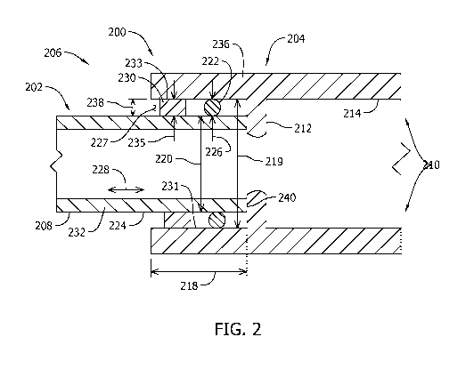
[0006] Figure 2 is a sectional view of an exemplary press-fit condulet
assembly coupled with a non-threaded conduit according to a first exemplary
embodiment of
the disclosure.
1
CA 03137998 2021-10-25
WO 2020/221476
PCT/EP2020/025196
[0007] Figure 3 is a perspective cross-sectional view of another exemplary
press-fit condulet assembly coupled with a conduit according to a second
exemplary
embodiment of the disclosure.
[0008] Figure 4 is a perspective cross-sectional view of a further exemplary
press-fit condulet assembly coupled with a conduit.
[0009] Figure 5 is a perspective cross-sectional view of yet another
exemplary press-fit condulet assembly coupled with a conduit.
[0010] Figure 6 is a process flow chart illustrating an exemplary method of
fabricating an electrical raceway with the press-fit condulet assemblies shown
in Figures 2-5.
DETAILED DESCRIPTION
[0011] Conventional conduits provide interconnection of rigid metal
conduits to fabricate a wire or cable raceway in an electrical system.
Threaded attachment of
rigid metal conduits to one another and to threaded condulets is
conventionally performed in
the installation of conduit systems, but is sub-optimal in some aspects.
[0012] For example, when a length of threaded conduit exceeds a length
needed for a given installation, the conduit is cut and new threads are
typically formed on the
remaining unthreaded end after cutting such that the conduit can still be
coupled to a threaded
condulet. However, forming new threads in the cut conduit can be time-
consuming,
dangerous, and laborious, thus increasing the cost, risk, and time to
construct a conduit
raceway. Moreover, forming threads on an end of a conduit that has been cut
without
creating imperfections (e.g., an angled end of the conduit, or burrs and the
like on the inside
or outside of the conduit) in the connections requires a level of skill that
the average worker
may or may not possess. Burrs and the like may damage the insulation of
electrical wires or
cables being pulled through the conduit and/or the threaded connection between
the conduit
and the condulet, resulting in undesirable reliability issues.
[0013] Press fit couplers have been proposed for use in the assembling of a
raceway, but are limited in some aspects. Specifically, known press fit
couplers can be
difficult to use with certain types of conduit, can be undesirably complicated
and expensive
from a component manufacturer perspective, require specialty tools to install,
or can be
2
CA 03137998 2021-10-25
WO 2020/221476
PCT/EP2020/025196
difficult from the installer's perspective to reliably complete an adequate
press fit that
includes an electrically-grounded connection.
[0014] Exemplary embodiments of improved, press fit conduit outlet
assemblies and condulet assemblies that may be universally used in the
fabrication of
electrical raceways are described below that overcome the deficiencies of
conventional
conduit interconnections discussed above. The inventive press fit conduit
outlet assemblies
disclosed herein establish an interference fit between a conduit and a
condulet assembly,
eliminating a need to use conventional, threaded conduit, simplifying
connections in certain
installations, and lowering the costs of conduit and time and labor costs to
complete rigid
metal conduit connections to construct an electrical raceway. To the extent
that threaded
conduit may still be utilized, the press fit conduit outlet assemblies may
still be used without
any need to create threads on any threaded conduits that are cut to a desired
length. As such,
the press fit conduit outlet assemblies can be used with threaded or
unthreaded conduits.
Further, the conduit outlet assemblies described herein desirably provide a
path to electrical
ground for a fabricated raceway. Method aspects in this disclosure will be in
part apparent
and in part explicitly discussed in the following description.
[0015] In a first aspect, an inventive press fit condulet assembly for a rigid
metal conduit raceway of an electrical system includes a body having at least
one mating end
configured to connect to an end of a rigid metal conduit via cold pressing
force. A sealing
element extends between at least one mating end and a surface of the rigid
metal conduit, and
a grounding element extends between at least a portion of at least one mating
end and the
surface of the rigid metal conduit to establish an electrical path to the
ground through the
connected rigid metal conduit and the body. A simpler, quicker and more
convenient, press
fit connection of rigid metal conduits in an electrical conduit raceway is
therefore possible
that does not depend on threaded connections, while ensuring reliable
mechanical
interconnection and an electrical ground path established between the condulet
assembly and
the rigid metal conduit. The sealing element and a grounding element may
extend between
an inner surface of the condulet assembly and an outer surface of the conduit,
or between an
inner surface of the conduit and an outer surface of the condulet assembly,
together with an
optional adapter if needed to accommodate varying inner and outer diameters of
the
condulets and conduits utilized to fabricate the raceway, as well as different
types of conduit
(e.g., threaded and non-threaded).
3
CA 03137998 2021-10-25
WO 2020/221476
PCT/EP2020/025196
[0016] In a second aspect, an inventive conduit outlet assembly is provided.
The conduit outlet assembly includes a condulet assembly, a gasket, and a
gripping ring. The
gasket is sized to circumscribe an outer surface of a conduit. The gripping
ring may be
electrically conductive, and is sized to circumscribe an end of the conduit
adjacent to the
gasket. A press fit condulet assembly is sized to receive the end of the
conduit with the
gasket and the gripping ring thereon. When the condulet assembly is cold
pressed to the
conduit, the gasket establishes a seal between an inner surface of the
condulet assembly and
an outer surface of the conduit, and such that the gripping ring provides
grounding for an
electrical raceway. An optional adapter may be provided to accommodate varying
inner and
outer diameters of the condulets and conduits utilized to fabricate the
raceway, as well as
different types of conduit (e.g., threaded and non-threaded).
[0017] In a third aspect, an inventive electrical conduit assembly or
electrical raceway is provided including a conduit having an end, and a
condulet assembly
press-fit to the end of the conduit. The condulet assembly may include a
receiver/condulet
having an inner surface sized to accept the end of the conduit and a gasket
coupled to the
conduit. The gasket establishes a seal between the inner surface of the
condulet and the outer
surface of the end of the conduit. An electrically-conductive gripping ring is
coupled to the
condulet and in surface contact with the inner surface of the condulet and the
outer surface of
the end of the conduit to provide an electrical ground path therebetween. An
optional adapter
may be provided to accommodate varying inner and outer diameters of the
condulets and
conduits utilized to fabricate the raceway, as well as different types of
conduit (e.g., threaded
and non-threaded).
[0018] In a fourth aspect, a rigid metal conduit raceway system is provided
including a plurality of rigid metal conduits, and a plurality of press fit
condulet assemblies
establishing mechanical and electrical connections between respective ones of
the plurality of
rigid metal conduits. Optional adapters may be provided to accommodate varying
inner and
outer diameters of the condulets and conduits utilized to fabricate the
raceway, as well as
different types of conduit (e.g., threaded and non-threaded). The system may
be provided in
kit form as a set of modular components that can be conveniently fabricated
into any desired
raceway configurations.
[0019] In a fifth aspect, an inventive method of fabricating an electrical
raceway is realized by the inventive conduit outlet assembly described herein.
The method
4
CA 03137998 2021-10-25
WO 2020/221476
PCT/EP2020/025196
includes providing a conduit and a press fit condulet assembly, with the
condulet assembly
having an inner diameter at an end thereof that is greater than an outer
diameter of the
conduit at an end of the conduit. The method includes positioning a gripping
ring about the
end of the conduit, wherein the gripping ring includes an electrically-
conductive material and
provides grounding for the raceway, positioning a gasket about the end of the
conduit such
that the gasket is adjacent to the gripping ring, and inserting the end of the
conduit into the
end of the condulet assembly until the gripping ring and the gasket are
disposed inside the
condulet assembly. The mechanical and electrical connection is completed via
cold pressing
of the condulet assembly to the end of the conduit. Cold pressing of the
condulet assemblies
further avoids time, expense and equipment to heat the components that other
types of
conventional processes require to join metal parts (e.g., welding) entail. An
optional adapter
may be provided to accommodate varying inner and outer diameters of the
condulets and
conduits utilized to fabricate the raceway, as well as different types of
conduit (e.g., threaded
and non-threaded).
[0020] The press fit conduit outlet assemblies and press fit methods for their
installation meet longstanding and unfulfilled needs in the art in simplifying
raceway
fabrication, allowing dramatic reduction in time and labor costs to complete a
raceway
installation while ensuring reliability of the mechanical and electrical
interconnections
established. In the contemplated embodiments, inventive press fit conduit
outlet assemblies
designed to realize the cold-press conduit connections reduce time and labor
costs by 30% to
50% over conventional raceway fabrication and installation processes.
[0021] Figure 1 illustrates an exemplary known condulet fitting, fitting, or
condulet 102 that is formed with hubs 104. Condulet 102 includes a wall 106
defining a
cavity 107. In the exemplary embodiment, wall 106 is formed with an aperture
that traverses
therethrough and that is normally covered by a cover 108. Wall 106 and cover
108 may be
fabricated from a variety of suitable materials including, but not limited to,
steel, plastic,
ceramic, and/or a combination of such materials.
[0022] Condulet 102 is formed with one or more hubs 104 to connect a rigid
metal conduit thereto. In the exemplary embodiment, hubs 104 are identical and
each is
formed with hub threads 110 that extend circumferentially about its inner
surface 112 at a
distal end 114 of each hub 104.
Each hub 104 has a substantially circular cross-sectional
shape that has a diameter 118 that is slightly larger than an outer diameter
(not shown in
5
CA 03137998 2021-10-25
WO 2020/221476
PCT/EP2020/025196
Figure 1) of the conduit (not shown in Figure 1) being coupled to the
condulet. In one
embodiment, a diameter 118 defined by an inner surface 112 is approximately
equal to 1/2
inches (1.27 cm), 1 1/2 inches (3.81 cm), 2 inches (5.08), and/or any other
size of a conduit
recognized as standard in the trade. Hub 104 further includes a bushing 124
that stops a
conduit from being inserted too far into condulet 102. The conduit is formed
with threads
that complement and mate with hub threads 110 to enable the conduit to couple
to hub 104.
[0023] Figure 2 is a sectional view of an exemplary improved conduit outlet
assembly 200 for use in coupling a conduit 202 to a condulet 204 in a cold
press fit
fabrication of an electrical raceway 206 that includes conduits 202. Conduit
202 may be a
rigid metal conduit. Conduit 202 may be of any size, including a standard
trade size, as
described above, and may include threads (not shown in FIG. 2) formed about
its outer
surface 208 at its end 224. In the exemplary embodiment, conduit 202 is a
hollow thin-
walled conduit that is not formed with threads. Moreover, in the exemplary
embodiment,
conduit 202 is formed with a substantially uniform outer diameter 220 defined
by its outer
surface 208.
[0024] In the exemplary embodiment, conduit outlet assembly 200 is formed
with and includes a condulet assembly 210. More specifically, condulet
assembly 210 is a
cast metal body formed into a condulet 204. Condulet 204 includes an annular
shoulder 212
that extend inwardly from its inner surface 214. Shoulder 212 is near an open
end 236 of
condulet assembly 210. Shoulder 212 extends generally radially inward to limit
an insertion
depth 218, i.e., a length that conduit 202 may be inserted within condulet
open end 236.
Surface of shoulder 212 may be smooth to limit scratches or damage to cables
or wiring. In
some embodiments, condulet assembly 210 may be formed with different sized
condulets to
enable different sized conduits to be coupled to condulet assembly 210.
[0025] In the exemplary embodiment, condulet 204 is formed with an inner
diameter 219 that is slightly larger than an outer diameter 220 of conduit
202. As such,
conduit 202 is sized to be at least partially inserted into condulet assembly
210, and more
specifically, into condulet 204. The inner diameter 219 of the condulet 204 is
exposed at the
distal end thereof, such that the body of the condulet 204 is open-ended for
an easier
installation of the conduit. Compared to existing press fit couplers for
electrical raceway
fabrication, there is no end wall in the condulet body at the distal end that
includes a smaller,
restricted opening having a reduced diameter through which the conduit is
inserted.
6
CA 03137998 2021-10-25
WO 2020/221476
PCT/EP2020/025196
Elimination of such an end wall simplifies the shape of the condulet 204 and
lowers its cost
of fabrication, while also simplifying the assembly for installation by
providing a larger
opening area for insertion of the conduit 202 at the distal end. Care is
required, however, to
avoid damaging the exposed sealing elements and grounding elements at the
distal end during
installation of the conduit.
[0026] Conduit outlet assembly 200, in the exemplary embodiment, further
includes a gasket 222. Gasket 222 may be fabricated from any material that
enables condulet
assembly 210 to function as described herein, including but not limited to
rubber, plastic,
and/or elastomer. Moreover, a cross-sectional shape of gasket 222 may have any
shape that
enables the gasket to function as described herein, including but not limited
to circular,
elliptical, square, rectangular, triangular, octagonal, and/or combinations
thereof.
Furthermore, gasket 222 may be fashioned as an 0-ring, a cylindrical band,
and/or any other
configuration that enables gasket 222 to function as described herein.
[0027] Gasket 222 is sized to circumscribe an end 224 of conduit 202. A
height 226 of gasket 222 is selected to enable gasket 222 to substantially
seal a gap 227
defined between conduit 202 and condulet assembly 210 when a compressive force
is applied
to condulet assembly 210. In the exemplary embodiment, gasket 222 is
fabricated from a
material that is at least partially elastic to enable gasket 222 to be
compressed between
condulet assembly 210 and conduit 202 as conduit end 224 is inserted into
condulet assembly
210. Moreover, in the exemplary embodiment, gasket 222 extends continuously
about
conduit end 224. Alternatively, gasket 222 may be segmented and multiple
pieces may be
positioned about conduit end 224 in a manner that facilitates sealing as a
compressive force is
applied to condulet assembly 210. Gasket 222 may be positioned at any location
along a
length 228 of conduit 202 that enables gasket 222 to function as described
herein. In each
embodiment, gasket 222 substantially seals gap 227 defined between condulet
assembly 210
and conduit 202 as gasket 222 is compressed and/or deformed by a compressive
force (e.g., a
press fitting).
[0028] Conduit outlet assembly 200 also includes a gripping ring 230. In the
exemplary embodiment, gripping ring 230 is fabricated from electrically-
conductive material.
Gripping ring 230 may be cylindrical, round, or any other suitable shape that
enables gripping
ring 230 to function as described herein. For example, in one embodiment,
gripping ring 230
may be formed to have a relatively simple rounded cross section (circular in
the illustrated
7
CA 03137998 2021-10-25
WO 2020/221476
PCT/EP2020/025196
example) and a rough outer surface. Gripping ring 230 interacts with conduit
outer surface
208 and/or with an inner surface 231 of condulet assembly 210 via friction
created between
the rough outer surface 233 of gripping ring 230 and conduit outer surface
208, and/or
friction created between the rough outer surface 233 of gripping ring 230 and
inner surface
231 of condulet assembly 210.
[0029] A thickness 235 of gripping ring 230 when uncompressed, is slightly
larger than a height 238 of gap 227 defined between inner surface 231 of
condulet assembly
210 at end 236 and conduit outer surface 208 at end 224. Thickness 235 of
gripping ring 230
is reduced as gripping ring 230 is compressed after conduit 202 is inserted
into condulet 204
during fabrication of raceway 206. Compression of the gripping ring changes
its cross
sectional shape to enlarge the surface area in contact with the conduit 202 on
one side and the
condulet 204 on the other side.
[0030] Gripping ring 230 is positioned adjacent to gasket 222 when raceway
206 is fabricated. Alternatively, gripping ring 230 may be positioned such
that gasket 222 is
between a tip 240 of conduit end 224 and gripping ring 230. When installed,
gripping ring
230 provides a path to the electrical ground in the raceway. For example, if
conduit wall 232
and/or condulet assembly 210 become electrically charged from static
electricity, an internal
short, and/or an external electrical source, gripping ring 230 provides a path
to electrical
ground.
[0031] In the exemplary embodiment, during assembly, conduit 202 is
inserted into condulet 204 at end 236. End 236 is then compressed onto conduit
end 224 via
an applied force of a press tool, such as a hydraulic tool. In the exemplary
embodiment, the
compression causes deformation of condulet end 236 which ensures conduit 202
is securely
coupled to condulet assembly 210. Moreover, during compression, gripping ring
230 is
compressed to ensure a ground is created between conduit 202 and condulet 204.
Furthermore, gasket 222 is also compressed to ensure the gap 227 between
conduit 202 and
condulet 204 is substantially sealed. Because of the deformation, the
connection established
is generally non-releasable such that condulet 204 is not reusable after
condulet 204 is
coupled to conduit 202 in a secure connection. As such, condulet 204 would
need to be
mechanically removed, such as via a cutting operation, from conduit 202 in
order for the
conduit to be re-used.
8
CA 03137998 2021-10-25
WO 2020/221476
PCT/EP2020/025196
[0032] Figure 3 illustrates another exemplary conduit outlet assembly 302,
with a conduit 202 inserted into condulet assembly 304. Conduit outlet
assembly 302
includes a cast metal body that is similar to that shown in Figure 2 and
accordingly the like
reference numerals are used in Figure 2 are used to identify like components
illustrated in
Figure 3. Compared to conduit outlet assembly 200 shown in FIG. 2, conduit
outlet assembly
302 includes an optional washer 306. Washer 306 may be fabricated from any
material that
enables washer 306 to function as described herein, including but not limited
to, a rubber
material, a metallic material, and/or a cork material. Moreover, washer 306
may have any
cross-sectional shape that enables washer 306 to function as described herein,
including but
not limited to circular, elliptical, square, rectangular, trapezoidal,
triangular, and/or octagonal.
Furthermore, washer 306 may extend continuously about conduit 202 in a single
piece, or
alternatively, may be made of multiple pieces spaced about conduit 202 in a
manner that
enables washer 306 to function as described herein.
[0033] In the exemplary embodiment, washer 306 is positioned between
gripping ring 230 and gasket 222. A radial thickness or height 307 of washer
306 may be
substantially the same as or less than a height 226 of gasket 222 when gasket
222 is
compressed. As such, washer 306 does not inhibit gasket 222 from creating a
substantially
fluid-impervious seal when condulet assembly 304 is compressed against conduit
202.
Washer 306 facilitates limiting movement of gasket 222 and/or gripping ring
230 and ensures
that gasket 222 remains spaced apart from gripping ring 230. As a result,
washer 306
facilitates maintaining a relative position of gasket 222 and/or gripping ring
230 during
insertion of conduit 202 within condulet 204, and as condulet 204 is
compressed onto conduit
202. Further, because gasket 222 is made of softer material than the metallic
material of
gripping ring 230, washer 306 serves as a separator between gripping ring 230
and gasket 222
to limit any damages to gasket 222 caused by gripping ring 230 when gripping
ring 230 rubs
against gasket 222.
[0034] Figure 4 illustrates another exemplary conduit outlet assembly 402
coupled with a conduit 404 that includes threads 406. In some embodiments,
conduit 404
does not include threads 406. Conduit outlet assembly 402 includes a metal
body that is
substantially similar to that shown in Figures 2 and 3 and accordingly like
reference numerals
used in respective Figures 2 and 3 are also used to identify like components
illustrated in
Figure 4. Compared to conduit outlet assemblies 200, 302 shown in FIGs. 2 and
3, conduit
9
CA 03137998 2021-10-25
WO 2020/221476
PCT/EP2020/025196
outlet assembly 402 includes a condulet assembly 408 that includes an adapter
410, besides a
condulet 412. Condulet 412 may be integrally formed. In the exemplary
embodiment,
adapter 410 facilitates coupling conduit 404 to conduit outlet assembly 402
and is coupled
between conduit 404 and condulet 412. In the exemplary embodiment, conduit 404
is formed
with threads 406 along its outer surface 208. However, conduit outlet assembly
402 is not
formed with mating threads along its inner surface 413. By virtue of the
adapter 410,
however, the threaded end of the conduit 404 may nonetheless be securely press
fit to the
condulet 412.
[0035] Adapter 410 enables conduit 404 to be inserted within and coupled to
conduit outlet assembly 402 such that gasket 222 and gripping ring 230 are
compressed
against conduit outer surface 208. Some or all of gasket 222, gripping ring
230, and if
applicable washer 306, are compressed against smooth conduit outer surface 414
as shown.
Because the adapter axially extends that position of the gasket 222, gripping
ring 230, and
washer 306 farther away from the condulet 412 on outer surface 208 of conduit
404, the
threads 406 do not affect the positioning of gasket 222, gripping ring 230, or
if applicable
washer 306 on conduit end 430, which may be press fit to the conduit 404 at a
location past
the threads 406. In another contemplated embodiment, however, one or more of
the gasket
222, gripping ring 230, and washer 306 may alternatively be pressed against
threads 406.
Either way, the threaded end of the conduit 404 can be inserted into the
condulet 412 for
press fit connection thereto without having to cut the threaded end of the
conduit 404 in order
to accomplish the press fit connection. As such, the adapter 410 allows for
more or less
universal use of the condulet 412 with different types of conduits (e.g.,
threaded and non-
threaded).
[0036] The adapter 410 also bridges different diameters of the condulet 412
and conduit 404 via different portions of the adapter 410 having different
internal and
external diameters to complete connections between conduit 404 and condulet
412 that
otherwise may not be possible. For instance, the adapter 410 may allow press
fit connection
of a conduit having an external diameter that equals or exceeds the internal
diameter of the
condulet, or may allow for press fit connection of a condulet having an
internal diameter that
well exceeds the external diameter of a conduit. More or less universal use of
the condulet
412 with different diameter conduits is therefore possible by virtue of the
adapter 410.
CA 03137998 2021-10-25
WO 2020/221476
PCT/EP2020/025196
[0037] In the exemplary embodiment, adapter 410 includes a compression
section 416, a transition section 418, and a coupling section 419. Gasket 222,
gripping ring
230, and if applicable washer 306, are positioned within compression section
416 of adapter
410 rather than in condulet 412. As such, only compression section 416 of the
adapter 410 is
press-fit via compressive force to complete the connection to the conduit 404.
Compression
of the condulet 412 is not required to complete the press fit connection.
Adapter 410 may be
fabricated from any material that enables adapter 410 to function as described
herein,
including but not limited to metallic materials, composite materials, and/or
plastic materials,
for example. To provide an electrical path to electrical ground between the
condulet 412 and
the conduit 404 through the adapter 410, the adapter 410 is fabricated to
include electrically-
conductive materials, either wholly or partially in the adapter construction.
The adapter 410
may further be fabricated using the same or different material(s) used to
fabricate the
condulet 412, including but not limited to cast steel or malleable iron.
[0038] Transition section 418 extends between compression and coupling
sections 416 and 419, respectively, and has an inner diameter 426 that is
smaller than an inner
diameter 428 of compression section 416. Inner diameter 426 is defined by a
smooth wall
432 that extends between compression section wall 434 and a wall 438 defining
an inner
diameter 436 of coupling section 419. In some embodiments, transition section
418 has a
length 440 that is selected to enable transition section 418 to extend about
an entire length or
at least majority of the length of conduit threads 406. In some embodiments,
choice of
length 440 is not influenced by the length of conduit threads 406.
Accordingly, inner
diameter 426 of transition section 418 is slightly larger than an outer
diameter 220 of conduit
404 such that conduit threads 406 are received snugly within transition
section 418.
Transition section 418 is not compressed when compression forces are applied
to adapter
410.
[0039] Coupling section 419 of adapter 410 is formed with an outer diameter
442 that is slightly smaller than an inner diameter 444 of condulet 412 at
condulet end 236.
As such, coupling section 419 is sized for insertion within condulet 412 in a
snug fit.
Condulet assembly 408 also includes a retaining ring 422 inserted within a
groove 424
formed in inner surface 214 of condulet 412 and/or a groove 425 formed in
outer surface 446
of adapter 410. Retaining ring 422 facilitates securely coupling adapter 410
with condulet
412. Moreover, ring 422 facilitates substantially sealing any gap defined
between adapter
11
CA 03137998 2021-10-25
WO 2020/221476
PCT/EP2020/025196
outer surface 446 and condulet inner surface 214. Retaining ring 422 may be a
continuous
piece that circumscribes outer surface 446 of adapter 410, or alternatively,
may be a
segmented member that includes multiple pieces spaced about outer surface 446.
Moreover,
retaining ring 422 may be fabricated from any material that enables ring 422
to function as
described herein, including but not limited to, rubber, plastic, metal, and
elastomer, for
example. Further, ring 422 may be fabricated from an electrically-conductive
material to
facilitate a ground path connection between the condulet 412 and the adapter
410.
[0040] Inner diameter 436 of coupling section 419 is smaller than conduit
outer diameter 220. As such, a transition shoulder 448 is defined between
transition section
inner wall 450 and coupling section inner wall 452. Transition shoulder 448
facilitates
limiting an insertion depth of conduit 404 within adapter 410. Similarly,
shoulder 212 of
condulet 412 facilitates limiting an insertion depth of adapter 410 within
condulet 412.
[0041] Figure 5 illustrates yet another exemplary conduit outlet assembly
502 coupled with a conduit 404. Conduit outlet assembly 502 includes a cast
metal body that
is similar to that shown in Figure 4, and hence like reference numerals in
Figure 4 are used to
indicate like features in Figure 5. Similar to condulet assembly 408 shown in
FIG. 4,
condulet assembly 504 of conduit outlet assembly 502 also includes an adapter
506, besides a
condulet 518. In the exemplary embodiment, adapter 506 includes a compression
section
416, a transition section 418, and a coupling section 510 that includes a
flared end 508. In
the exemplary embodiment, adapter 506 facilitates coupling conduit 404 to
condulet 518 and
is coupled between conduit 404 and condulet 518. More specifically, in the
exemplary
embodiment, conduit 404 is formed with threads 406 along its outer surface
208. However,
conduit outlet assembly 502 is not formed with mating threads along its inner
surface 413.
[0042] Adapter 506 may be fabricated from any material that enables
adapter 506 to function as described herein, including but not limited to
metallic materials,
composite materials, and/or plastic materials, for example.
[0043] Coupling section 510 of adapter 506 is formed with an outer diameter
442 that is slightly smaller than an inner diameter 444 of condulet 518 at
condulet end 512.
Moreover, coupling section 510 includes a flared end 508. Flared end 508
compresses
.. radially inwardly while adapter 506 is inserted into condulet 518 and then
snaps outwardly to
be retained by a retaining shoulder 514 formed within condulet end 512.
Alternatively,
12
CA 03137998 2021-10-25
WO 2020/221476
PCT/EP2020/025196
adapter 506 and condulet 518 are preassembled such that the flared end 508 has
been
disposed within condulet end 512.
[0044] Although conduits 404 shown in Figures 4 and 5 have threads,
condulet assemblies 408 and 504 can also be used with conduit 202 (shown in
Figures 2 and
3), which does not include threads at its end, and vice versa. That is,
condulet assemblies 210
and 304 (shown in respective Figures 2 and 3) may likewise be used with a
conduit 404 that
includes threads 406 or a conduit without threads. Condulet assemblies
disclosed herein may
also be used with a conduit including a tapered end or tapered threads with or
without an
adapter.
[0045] Further, adapter 410, 506 shown in Figures 4 and 5 may be used to
couple conduit 404, threaded or unthreaded, with a conventional condulet 102
that has
threaded hubs 104. In operation, conventional condulet 102 is used in place of
condulet 412,
518. As a result, threads need not to be created on the conduit or cumbersome
coupling of
long conduit into a condulet can be avoided.
[0046] While a single condulet assembly/conduit connection and a single
conduit outlet assembly is shown in Figures 2-5, in contemplated embodiments
the condulets
and condulet assemblies shown in Figures 2-5 would be provided in combination
in the same
press fit condulet to interconnect two or more conduits in any desired
orientation to the same
condulet. For example, the press-fit assemblies described in Figures 2-5 could
be integrated
on opposing ends of the same condulet assembly to realize a similar conduit
connection and
outlet to the condulet shown in Figure 1, albeit with press-fittings instead
of threads. In such
a combination, the condulets used on each end may be the same or different
from one another
to accommodate, for example, a threaded end of conduit on one side and a non-
threaded end
of the conduit on the other side. Numerous variations are possible in this
regard to connect
the same or different types of conduits in-line to one another (i.e.,
substantially aligned to
extend along a common axis), at right angles to one another, or at oblique
angles to one
another as desired or as needed to complete raceway installations at
particular sites.
[0047] A rigid metal conduit raceway system may be assembled including
any number of rigid metal conduits, and any number of press fit condulet
assemblies
establishing mechanical and electrical connections between respective ones of
the plurality of
rigid metal conduits. The conduits and/or condulet assemblies described herein
may be
13
CA 03137998 2021-10-25
WO 2020/221476
PCT/EP2020/025196
provided as modular components in the form of a kit to construct raceway
systems of a
predetermined type that may avoid any need to cut the conduits on a job site,
or as a kit of
modular component parts that may be creatively used by an installer to
fabricate raceway
runs in any configuration desired.
[0048] Figure 6 shows an exemplary method 600 of fabricating an electrical
raceway. Method 600 includes providing 602 a conduit and a press fit condulet
assembly.
The press fit condulet assembly may include any of the examples or embodiments
described
above, and accordingly may include an inner diameter at an end of the condulet
assembly
greater than the outer diameter of the conduit at an end of the conduit.
Method 600 further
includes positioning 604, a gripping ring, such as any of the gripping rings
described above,
about an end of the conduit. Method 600 also includes positioning 606 a
gasket, including
any of the gaskets described above, about the end of the conduit such that
gasket is adjacent
to the gripping ring. Further, method 600 includes inserting 608 an end of the
conduit into
the end of the condulet assembly until the gripping ring and the gasket are
positioned inside
the condulet assembly. The assembly is completed by applying a cold
compression force to
the outer surface of the condulet assembly to compress the gasket, the
gripping ring, and
either the condulet or an adapter to couple to the conduit.
[0049] The configurations of the conduit and conduit outlet assembly may
be reversed from the embodiments illustrated in another contemplated
embodiment. That is,
the condulet may be inserted into a conduit directly or indirectly through an
adapter, while
still providing a sealed connection including an electrical ground path.
Similarly, the
configurations of the adapter and the condulet may be reversed such that the
condulet is
inserted into an adapter to complete a sealed connection including a ground
path.
[0050] The exemplary embodiments of conduit outlet assemblies described
herein include a gasket for sealing the connection between condulet assemblies
and the
conduit, a gripping ring that provides grounding of the raceways, and an
optional washer.
Threads do not need to be created before connecting condulet assemblies with
conduits.
Conduit outlet assemblies and condulet assemblies described herein may be used
with
unthreaded or threaded sections of conduits, replacing conduit connections via
threaded hubs.
The seal formed by the conduit outlet assembly keeps water from entering into
the conduit.
14
CA 03137998 2021-10-25
WO 2020/221476
PCT/EP2020/025196
[0051] The benefits and advantages of the inventive concepts are now
believed to have been amply illustrated in relation to the exemplary
embodiments disclosed.
For example, the embodiments described herein facilitate raceway fabrication
without
creating threads on conduits or without using conduit having threads, thereby
reducing or
eliminating cost, safety risks, and labor associated with threaded connections
between
conduits and condulets. Avoiding a need to create threads also reduces or
eliminates
imperfections such as burrs in the conduits, thereby reducing or eliminating
damage to
electrical wires when being pulled through and/or weakened threaded
connection.
Additionally, embodiments of the systems and methods provide a secure
connection of
conduits through which electrical wires run. For example, the seal formed by
the conduit
outlet assemblies described herein keeps water from entering inside conduits
and interfering
with electricity carried by electrical wires, thereby eliminating additional
material or
processes to seal the connections in known systems and methods. Further,
embodiments of
the systems and methods provide a grounding path for the raceway. For example,
gripping
rings of the conduit outlet assemblies described herein also serve as a
grounding path for the
raceway, thereby eliminating additional material or procedures to establish
grounding path
for the raceway, especially when the conduit and condulets are not formed with
electrically-
conductive material.
[0052] An embodiment of a conduit outlet assembly for a rigid metal
conduit raceway of an electrical system has been disclosed. A conduit outlet
assembly
includes a gasket, a gripping ring, and a condulet assembly. The gasket is
sized to
circumscribe an outer surface of a rigid metal conduit of the rigid metal
conduit raceway.
The gripping ring is sized to circumscribe the outer surface of the rigid
metal conduit. The
condulet assembly is sized to receive the rigid metal conduit, and includes an
adapter and a
condulet. The adapter includes a compression section and a coupling section,
wherein the
compression section is sized to receive the rigid metal conduit with the
gasket and the
gripping ring disposed thereon. The condulet is sized to receive the coupling
section of the
adapter.
[0053] Optionally, after the condulet assembly is press-fitted onto the rigid
metal conduit, the gasket establishes a seal between the condulet assembly and
the rigid metal
conduit. The gripping ring includes an electrical conductive material and
provides grounding
for the rigid metal conduit raceway. The conduit outlet assembly is configured
to receive a
CA 03137998 2021-10-25
WO 2020/221476
PCT/EP2020/025196
rigid metal conduit having an unthreaded end, and the gasket is configured to
establish a seal
between the condulet assembly and the rigid metal conduit at the unthreaded
end. The
adapter further includes a transition section formed between the compression
section and the
coupling section, the transition section having an inner diameter between an
inner diameter of
the compression section and an inner diameter of the coupling section. The
adapter further
includes a transition shoulder defined between the transition section and the
coupling section,
the transition shoulder configured to restrict the rigid metal conduit from
being inserted
farther into the condulet assembly. The conduit outlet assembly further
includes a ring,
wherein the condulet includes a groove formed in an inner surface of the
condulet and sized
to receive the ring. The coupling section includes a flared end, and the
condulet includes a
retaining shoulder configured to retain the flared end when the coupling
section is inserted
into the condulet. The condulet includes a shoulder extending
circumferentially from an
inner surface of the condulet and configured to restrict the coupling section
of the adapter
from being inserted farther into the condulet.
[0054] Another embodiment of a conduit outlet assembly for a rigid metal
conduit raceway of an electrical system has been disclosed. The conduit outlet
assembly
includes a gasket, a gripping ring, and a condulet assembly. The gasket is
sized to
circumscribe an outer surface of a rigid metal conduit of the rigid metal
conduit raceway.
The gripping ring includes an electrical conductive material and sized to
circumscribe the
outer surface of the rigid metal conduit. The condulet assembly is sized to
receive the rigid
metal conduit with the gasket and the gripping ring disposed thereon. After
the condulet
assembly is press-fitted onto the rigid metal conduit, the gasket establishes
a seal between the
condulet assembly and the rigid metal conduit and the gripping ring provides
grounding for
the rigid metal conduit raceway.
[0055] Optionally, the conduit outlet assembly is configured to receive a
rigid metal conduit having an unthreaded end, and the gasket is configured to
establish a seal
between the condulet assembly and the rigid metal conduit at the unthreaded
end. The
condulet assembly includes a condulet sized to receive the rigid metal conduit
with the gasket
and the gripping ring disposed thereon. The condulet assembly includes a
condulet including
a shoulder extending circumferentially from an inner surface of the condulet.
The condulet
assembly further includes an adapter including a compression section and a
coupling section,
wherein the compression section is sized to receive the rigid metal conduit
with the gasket
16
CA 03137998 2021-10-25
WO 2020/221476
PCT/EP2020/025196
and the gripping ring disposed thereon, and a condulet sized to receive the
coupling section of
the adapter. The adapter further includes a transition section formed between
the
compression section and the coupling section, the transition section having an
inner diameter
between an inner diameter of the compression section and an inner diameter of
the coupling
section. The conduit outlet assembly further includes a ring, wherein the
condulet includes a
groove formed in an inner surface of the condulet and sized to receive the
ring. The coupling
section includes a flared end, and the condulet includes a retaining shoulder
configured to
retain the flared end when the coupling section is inserted into the condulet.
The condulet
includes a shoulder extending circumferentially from an inner surface of the
condulet and
configured to restrict the coupling section of the adapter from being inserted
farther into the
condulet.
[0056] An embodiment of a method of fabricating a rigid metal conduit
raceway of an electrical system has been disclosed. The method includes
providing a rigid
metal conduit and a condulet assembly, the condulet assembly sized to receive
the rigid metal
conduit. The method further includes circumscribing an outer surface of the
rigid metal
conduit with a gripping ring at an end of the rigid metal conduit, wherein the
gripping ring
includes an electrically-conductive material. The method also includes
circumscribing the
outer surface of the rigid metal conduit adjacent the gripping ring with a
gasket, and inserting
the end of the rigid metal conduit into an end of the condulet assembly until
the gripping ring
and the gasket are disposed inside the condulet assembly. Further, the method
includes
applying compression force to an outer surface of the condulet assembly to
compress the
condulet assembly, the gasket, and the gripping ring against the rigid metal
conduit such that
the gasket establishes a seal between the condulet assembly and the rigid
metal conduit. The
gripping ring provides grounding for the rigid metal conduit raceway.
[0057] Optionally, providing a rigid metal conduit and a condulet assembly
further includes providing an adapter and a condulet, the adapter including a
compression
section and a coupling section, the compression section sized to receive the
rigid metal
conduit with the gasket and the gripping ring disposed thereon, and the
condulet sized to
receive the coupling section of the adapter. Inserting the end of the rigid
metal conduit
further includes coupling the coupling section of the adapter to the condulet
to form the
condulet assembly, and inserting the end of the rigid metal conduit into the
compression
section of the adapter until the gripping ring and the gasket are disposed
inside the condulet
17
CA 03137998 2021-10-25
WO 2020/221476
PCT/EP2020/025196
assembly. Applying compression force further includes applying compression
force to an
outer surface of the compression section of the adapter to compress the
compression section,
the gasket, and the gripping ring against the rigid metal conduit.
[0058] While exemplary embodiments of components, assemblies and
systems are described, variations of the components, assemblies and systems
are possible to
achieve similar advantages and effects. Specifically, the shape and the
geometry of the
components and assemblies, and the relative locations of the components in the
assembly,
may be varied from that described and depicted without departing from
inventive concepts
described. Also, in certain embodiments certain of the components in the
assemblies
described may be omitted to accommodate particular types of conduit or the
needs of
particular installations, while still providing cost effective cold press fit
coupling connections
of conduit for electrical wiring or cabling.
[0059] This written description uses examples to disclose the invention,
including the best mode, and also to enable any person skilled in the art to
practice the
invention, including making and using any devices or systems and performing
any
incorporated methods. The patentable scope of the invention is defined by the
claims, and
may include other examples that occur to those skilled in the art. Such other
examples are
intended to be within the scope of the claims if they have structural elements
that do not
differ from the literal language of the claims, or if they include equivalent
structural elements
with insubstantial differences from the literal languages of the claims.
18