Note : Les descriptions sont présentées dans la langue officielle dans laquelle elles ont été soumises.
CA 03157155 2022-04-06
Spice mill part and method for producing a spice mill part
The invention relates to a spice mill part, in particular a spice
mill lower part, for a spice mill, with a housing which consists at least
partially of a plastic material, and can be rotatably connected to another
spice mill part, in particular a spice mill upper part, wherein a receiving
element is provided on the housing, in which is arranged a milling element,
in particular a milling ring, made from a ceramic material. Furthermore,
the invention relates to a spice mill and a spice grinder, each with such
a spice mill part, together with a method for producing the spice mill
part.
Generic spice mills usually have a spice mill lower part and a spice
mill upper part, that is to say, a rotor and a stator, both of which are
provided with milling elements for the milling of spices, wherein the spice
mill upper part is usually rotatably mounted relative to the spice mill
lower part, which is connected to a spice container. By rotation of the
spice mill upper part relative to the spice mill lower part, the milling
elements are rotated relative to each other and the spice is thereby milled
in a milling gap between the milling elements.
Spice mill parts, and spice mills, of the type mentioned in the
introduction, are of known art from DE 10 2015 121 237 B4, or DE 10 2016
106 597 B4, amongst other publications.
Other spice mills are of known art from WO 2016/207740 Al, CN
107041695 A and JP H04135462 A.
The housings of spice mill parts are typically produced in a plastic
injection moulding process. If a ceramic milling element is provided, this
is manufactured separately from the production of the housing in a separate
production process, and is then inserted into a receiving element of the
housing. Disadvantageously, ceramic parts, in particular, have
comparatively large manufacturing tolerances, such that the outer diameter
of the milling element can often fluctuate by approx. 0.5 to 0.8 mm for
conventional mill sizes. In order nevertheless to ensure that the milling
element can be reliably inserted into the receiving element, the inner
diameter of the receiving element is usually designed such that even
milling elements with the largest dimension within the tolerance range can
still easily be inserted into the receiving element. This leads to the
fact that the outer diameter of the ceramic part is in all cases smaller
than the inner diameter of the receiving element, and thus the ceramic
part is mounted floating in the receiving element. Disadvantageously, the
problem often arises that very fine and therefore invisible hairline cracks
can occur in the milling elements during production of the milling
Date Recue/Date Received 2022-04-06
CA 03157155 2022-04-06
- 2 -
elements, which can then lead to fracture or chipping of parts of the
milling element when using the spice mill part, due to the compressive
forces acting from the inside to the outside during a milling process and
the floating mounting of the milling element. In the worst case, a fracture
of a milling element can lead to a completely defective spice mill. In the
case of chippings, the chipped parts of the milling element can get onto
food together with the milled spices, and can therefore pose a danger.
Most fractures and chippings occur in the milling rings in the spice mill
lower part.
In view of the above statements, it is the object of the present
invention to alleviate, or even eliminate completely, the disadvantages of
the prior art. In particular, it is the object of the invention to provide
a spice mill part of the type mentioned in the introduction, in which the
risk of a fracture or chipping of the milling element is reduced or
completely avoided.
This object is achieved by a spice mill part with the features of
Claim 1.
Accordingly, in accordance with the invention provision is made for
the milling element to be clamped in the receiving element in a force fit
by means of a compressive force directed, in particular, essentially
radially inwards, and acting on a closed outer bearing face of the milling
element, wherein the compressive force acts essentially along the entire
circumference on the external bearing face of the milling element.
Advantageously, the inwardly directed compressive force acting on the outer
bearing face preferably achieves an essentially full-surface contact
between the outer bearing face of the milling element and an inner bearing
face of the receiving element, such that compressive forces acting on the
milling element from the inside during a milling process are transmitted
to the receiving element over a large region, thus reducing the risk of
the propagation of hairline cracks, and thereby considerably reducing the
risk of consequential damage such as fractures or chipping. The clamping
provided by the force fit of the milling element in the spice mill part
also prevents unintentional displacements of the same, which can further
reduce the risk of other defects of the spice mill, such as the wedging of
milling elements that can be rotated relative to each other. The force fit
between the milling element and the receiving element can, in particular,
be created in that the (nominal) inner circumference of the receiving
element is smaller than the (nominal) outer circumference of the milling
element when it is produced, that is to say, in the uninserted state of
the milling element. In other words, during its production the receiving
Date Recue/Date Received 2022-04-06
CA 03157155 2022-04-06
- 3 -
element has a (nominal) inner diameter that is smaller than a (nominal)
outer diameter of the milling element. The (nominal) inner diameter of the
receiving element is preferably smaller than the (nominal) outer diameter
of the milling element by at least 0.01 mm, even more preferably by 0.1
mm. The prefix "(nominal)" is intended to make clear that tolerances occur
during production of the spice mill part. If reference is made to dimensions
in the following, reference is being made to the nominal dimension in each
case, unless otherwise specified. As a result, the milling element is
pressed into the receiving element in the assembled state of the spice
mill part. The pressing-in or clamping of the milling element takes place
essentially along the entire circumference of the outer bearing face. Here
an inner bearing face of the receiving element presses against the outer
bearing face of the milling element. In comparison, in the prior art there
is no force fit on a regular basis, but just a positive form fit between
the milling element and the receiving element to provide security against
rotation. Here the compressive force on the outer bearing face of the
milling element is preferably generated by a wall of the receiving element.
The wall of the receiving element can, in particular, be designed to be
essentially cylindrical. The inner bearing face of the receiving element
is preferably essentially round. The outer bearing face of the milling
element is also preferably essentially round. In order to receive the
milling element, the receiving element can have what is, in particular, an
essentially circular insertion opening on an upper edge region. In
accordance with the invention, the compressive force acts on the outer
bearing face essentially along the entire circumference. However, the
receiving element can have one or a plurality of spreader openings which
can facilitate the insertion of the milling element. Needless to say, the
receiving element cannot then exert an inwardly directed compressive force
at the locations of the spreader openings. The compressive force can be
exerted on at least half, in particular on at least two thirds, or at least
three quarters, of the outer bearing face of the milling element. The
housing is at least partially made from a plastic material, and can have
been produced, for example, by means of a plastic injection moulding
process. In the context of compressive force, "inwardly" means towards a
central longitudinal axis of the spice mill part, which can also coincide
with the axis of rotation of the spice mill. If the milling element takes
the form, for example, of a milling ring, it is advantageous if the
compressive force is directed radially inwards. A milling ring has an
essentially circular outer bearing face, and has milling projections on an
inner face. The spice mill part, which is designed in particular as a spice
Date Recue/Date Received 2022-04-06
CA 03157155 2022-04-06
- 4 -
mill lower part, is preferably rotatably connected by way of a snap-on
connection to another spice mill part, in particular a spice mill upper
part. The other spice mill part can have another milling element, in
particular a milling cone, with milling projections on an outer surface.
Here the spice mill parts can be connected to each other such that the
other milling element is at least partially inserted into the milling
element, such that a milling gap is created between the two milling
elements, in which the spice can be milled. The inner bearing face of the
receiving element preferably abuts directly and immediately against the
outer bearing face of the milling element, essentially along the entire
circumference of the milling element, except for any projections of the
milling element.
For the purposes of the present disclosure, directional indications
such as "up", "down", "inside" and "outside" refer to a rest position, in
which the spice mill part, that is to say, the spice mill, is usually
connected to a spice container, and the spice container is placed on the
bottom surface located opposite the receiving opening.
In order to facilitate the insertion of the milling element into the
receiving element during the completion of the spice mill part, the
receiving element can have at least one, preferably two, in particular
opposing, spreader recess/es, for purposes of at least partially spreading
apart the receiving element. With the aid of the spreader recesses, the
receiving element can be spread apart more easily, that is to say, can be
expanded in diameter more easily, in order to insert the milling element.
The spreading apart process can take place by means of the application of
force. After the force has been removed, the receiving element will try to
return to its original shape, by virtue of the restoring force of the
material. If in the meantime the milling element has been inserted into
the receiving element, the receiving element will, from that point onwards,
exert the compressive force onto the milling element. The spreader recess
can be designed, for example, as a slot, an incision, an opening, or a
notch. The spreader recess preferably extends from an upper edge of the
receiving element, and in particular, parallel to the central longitudinal
axis, in the direction of a lower edge of the receiving element.
In order to facilitate the insertion of the milling element into the
receiving element, provision can be made, in particular for production
reasons, for the receiving element to have a step, in particular a
circumferential step, on the inner bearing face. By means of the step, two
regions with differing inner diameters can be created. The step preferably
creates a receiving element with an upper region located at the insertion
Date Recue/Date Received 2022-04-06
CA 03157155 2022-04-06
- 5 -
opening of the receiving element, and a lower region, wherein the lower
region has a smaller inner diameter than the upper region. The inner
diameter of the upper region of the receiving element is preferably at
least 0.1 mm, more preferably at least 0.5 mm, larger than the inner
diameter of the lower region of the receiving element.
Accordingly, the outer bearing face of the milling element can have
a step, in particular a circumferential step. By means of the
circumferential step, the outer bearing face is also divided into an upper
and a lower region, wherein the lower region preferably has a smaller outer
diameter than the upper region. The outer diameter of the upper region of
the milling element is preferably at least 0.1 mm, even more preferably at
least 0.5 mm, larger than the outer diameter of the lower region of the
milling element. By this means, the milling element can first be inserted
with a smaller diameter, which essentially corresponds to the inner
diameter in the lower region of the receiving element, into the receiving
region of larger diameter, without the application of a compressive force,
before the two loosely joined parts are fed to a press, in which a plurality
of milling elements are generally pressed into the respective receiving
elements with the required compressive force, such that the section of the
milling element with the smaller diameter is surrounded by the section of
the receiving element with the smaller diameter, and the section of the
milling element with the larger diameter is surrounded by the section of
the receiving element with the larger diameter.
It is advantageous if the milling element has at least one projection
on the outer bearing face, preferably extending over the entire height of
the outer bearing face. The projection can serve a plurality of purposes
at the same time. On the one hand, in this region the milling element is
thickened and reinforced, so as to reduce the risk of fracture. On the
other hand, the projection can serve to provide security against rotation.
For this purpose, if a spreader recess is provided in the receiving element,
the projection can be at least partially received in this recess.
Furthermore, the milling element can also have an upper collar on an upper
edge. The collar fits on the upper edge of the receiving element, more
precisely, on the insertion opening, and thus determines how far the
milling element can penetrate into the receiving element. The collar can
also interact with blocking elements of the receiving element, so that a
security against rotation of the milling element in the receiving element
is created. For this purpose, the collar can also have flattened sections,
or recesses, which interact with the blocking elements of the receiving
element.
Date Recue/Date Received 2022-04-06
CA 03157155 2022-04-06
- 6 -
In one form of embodiment of the spice mill part, provision is made
for the projection to have essentially the same contour as the spreader
recess, and for the projection preferably to protrude from the outer
bearing face, essentially in accordance with an upper collar.
In order, on the one hand, to allow the milling element to be inserted
into the receiving element without destroying the receiving element, and,
on the other hand, to generate a suitable compressive force that can
prevent hairline cracks or their propagation, it has been shown that it is
beneficial if the nominal diameter of the inner bearing face of the
receiving element is selected during its production such that it is between
1 % and 3 %, preferably between 1.5 % and 2.5 %, even more preferably
essentially 2 % smaller than the nominal diameter of the outer bearing
face of the milling element.
In order to achieve as planar a contact as possible between the outer
bearing face of the milling element and the inner bearing face of the
receiving element over the entire circumference, it is advantageous if,
taking into account the manufacturing tolerances of the receiving element
and the milling element, the largest possible inner diameter of the inner
bearing face of the receiving element essentially corresponds to the
smallest possible outer diameter of the outer bearing face of the milling
element. Accordingly, an interference fit is ensured even in the case of
a non-beneficial coincidence of manufacturing deviations of a receiving
element and a milling element (outer diameter of the milling element small,
inner diameter of the receiving element large).
In a preferred form of embodiment, provision is made for the receiving
element to form a support projection for the milling element on the inner
face, which extends radially inwards, essentially at right angles to the
inner face of the receiving element. On the one hand, the support projection
can serve as a bearing surface for the milling element and/or, on the other
hand, if the spice mill part is connected to another spice mill part, it
can block the other milling element from penetrating too deeply into the
receiving element.
The housing is preferably made from polyoxymethylene, polycarbonate,
polypropylene, ABS (acrylonitrile-butadiene-styrene
copolymers),
polymethyl methacrylate, polyethylene, polyolefins and/or biopolymers.
In order to be able to connect a spice mill part to a spice container,
it is advantageous if a thread is provided for connection to the spice
container.
In order that a connection can be rotatably connected to another
spice mill part, it is advantageous if a preferably circumferential snap-
Date Recue/Date Received 2022-04-06
CA 03157155 2022-04-06
- 7 -
on projection is provided for connection to the other spice mill part. The
snap-on projection can be snapped together with another snap-on projection
of the other spice mill part, so that any unintentional detachment of the
other spice mill part from the spice mill part is prevented, but a rotation
of the two spice mill parts relative to each other is made possible.
A development of the invention relates to a spice mill for a spice
grinder, wherein a spice mill lower part is provided in accordance with
the above statements, which is rotatably connected to a spice mill upper
part by way of a snap-on connection, wherein the spice mill upper part has
another milling element, in particular a milling cone. The spice mill can
be connected to a spice container by way of a thread. The unmilled spice
can enter the spice mill by way of an input face, can be milled by rotation
in a milling gap formed between the two milling elements, and can exit the
spice mill on an output face.
In a development, the invention also comprises a spice grinder with
a spice container and a spice mill of the type described above. The spice
container is preferably connected to the spice mill by way of a thread.
Furthermore, the invention relates to a method for producing a spice
mill part, in particular a spice mill lower part, as described above. The
method in accordance with the invention comprises the following steps:
- Production of a milling element, in particular a milling ring,
consisting of a ceramic material;
- Production of a housing with a receiving element for the milling
element by means of a plastic injection moulding process;
Insertion of the milling element into the receiving element,
such that the milling element is clamped in the receiving element in a
force fit, by means of a compressive force directed, in particular,
essentially radially inwards, and acting on a closed outer bearing face of
the milling element.
With regard to the advantages and features of the spice mill part,
reference is made to the above statements. The milling element is produced
in a production process that is independent of the production of the
housing. There are a plurality of possibilities for the insertion of the
milling element into the receiving element.
In accordance with a first embodiment, the milling element is inserted
into the receiving element before the receiving element has cooled down to
room temperature. In this context, room temperature means a temperature of
25 C. It is particularly beneficial if the milling element is inserted
into the receiving element when the housing is (still) at a temperature of
at least 35 C. This is because, on the one hand, the material is (still)
Date Recue/Date Received 2022-04-06
CA 03157155 2022-04-06
- 8 -
deformable and, on the other hand, the shrinkage of the material, which
later generates and increases the compressive force on the milling element,
has not (yet) set in. With regard to the production process, it is
beneficial if the milling element is inserted into the receiving element
within 180 seconds after removal of the housing from an injection mould.
In order to make the insertion of the milling element independent in
terms of time of the temperature or the production process of the housing,
it is beneficial if the receiving element has at least one spreader recess,
and the receiving element is spread apart for the insertion of the milling
element. By means of the spreader recess, the inner diameter of the
receiving element can be expanded, and the milling element can thus be
inserted. This process can also take place at room temperature.
In what follows, the invention is explained in more detail with the
aid of figures, to which, however, it is not intended to be limited:
Fig. 1 shows a milling element in the form of a milling ring in
accordance with a first form of embodiment;
Fig. 2 shows a plan view onto a spice mill part in accordance with a
first form of embodiment with a milling ring;
Fig. 3 shows a cross-section of the spice mill part along the
sectional plane III-III from Fig. 2;
Fig. 4 shows a cross-section of the spice mill part along the
sectional plane IV-IV from Fig. 2;
Fig. 5 shows a side view of a spice mill part in accordance with the
first form of embodiment;
Fig. 6 shows a milling element in the form of a milling ring in
accordance with a second form of embodiment;
Fig. 7 shows a plan view onto a spice mill part in accordance with a
second form of embodiment with a milling ring;
Fig. 8 shows a cross-section of the spice mill part along the
sectional plane VIII-VIII from Fig. 7;
Fig. 9 shows a cross-section of the spice mill part along the
sectional plane IX-IX from Fig. 7;
Fig. 10 shows a side view of the spice mill part in accordance with
the second form of embodiment;
Fig. 11 shows a milling ring and a receiving element in a detail view
in cross-section;
Fig. 12 shows a milling ring in a side view; and
Fig. 13 shows a cross-section of a spice grinder.
Two forms of embodiment of the invention are described in more detail
below. First the first, and then the second, form of embodiment will be
Date Recue/Date Received 2022-04-06
CA 03157155 2022-04-06
- 9 -
explained.
Fig. 1 shows a milling element 1 in the form of a milling ring 2 made
from a ceramic material. The milling element 1 has milling projections 3
on its inner face, which can interact with milling projections of another
milling element, for example a milling cone (not shown, see Fig. 13), in
order to mill a material that is to be milled in a milling gap located
between the two milling elements. The milling ring 2 shown has two different
types of milling projections 3 on its inner face, namely coarse milling
projections 4 for coarse milling, and fine milling projections 5 for fine
milling.
On its outer face, the milling ring 2 has a closed outer bearing face
6 and at least one projection 7, which thickens the milling ring 2 at that
position. On an upper edge 8, the milling ring 2 has an outwardly projecting
collar 9. The projection 7 adjoins the collar 9, and, in the embodiment
shown, extends as far as a lower edge 10 of the milling ring 2, and thus
essentially over the entire height of the outer bearing face 6. The collar
9 runs along the upper edge 8, and has a flat 11 on each of two opposing
faces, which flats can interact with blocking elements 12 of a receiving
element 13 so as to secure the milling ring 2 in the receiving element 13
against rotation (see Fig. 2).
Fig. 2 shows a plan view onto a spice mill part 14 in the form of a
spice mill lower part 15 in a first form of embodiment. It can be seen
that the milling ring 2 from Fig. 1 is inserted in the receiving element
13. Furthermore, it can be seen that the flats 11 of the collar 9 interact
with the blocking elements 12 of the receiving element 13 so as to achieve
security against rotation.
Fig. 3 shows the spice mill lower part 15 in cross-section along the
sectional plane
from Fig. 2. The spice mill lower part 15 has a
housing 16 made from a plastic material, with a receiving element 13, which
has an inner bearing face 17, and into which the milling ring 2 from Fig.
1, as shown, is inserted with a force fit. For the insertion of the milling
ring 2, the receiving element has an insertion opening 18 on its upper
face. The force fit is created by the compressive force of a wall 19 of
the receiving element 13 acting on the milling ring 2 (illustrated by
arrows). The compressive force acts radially inwards onto the outer bearing
face 6 of the milling ring 2 towards a central longitudinal axis 20 of the
spice mill part 14. The application of force, and the intimate reception
of the milling ring 2 in the receiving element 13, prevents the formation
and propagation of hairline cracks in the milling ring 2. The compressive
force arises because the receiving element 13 has a (nominal) inner
Date Recue/Date Received 2022-04-06
CA 03157155 2022-04-06
- 10 -
diameter 21, 21' during production that is smaller than a (nominal) outer
diameter 22, 22' of the milling ring 2. This is illustrated by the
overlapping cross-sections of the receiving element 13 and the milling
ring 2. In other words, in a bearing region the milling ring 2 is larger
in cross-section than the inner diameter of the receiving element 13. By
the insertion of the milling ring 2 into the receiving element 13, the
receiving element 13 is widened. By virtue of the restoring force of the
material of the receiving element 13, the compressive force acts on the
outer bearing face 6 of the milling ring 2. The compressive force acts
essentially along the entire circumference of the outer bearing face 6.
The wall 19 is essentially cylindrical in shape and therefore has a round
inner contour when seen in plan view. The outer bearing face 6 of the
milling ring 2 is also essentially round.
In Fig. 1 and Fig. 3 it can be seen that the outer bearing face 6 of
the milling ring 2 has a circumferential step 23. The circumferential step
23 of the milling ring 2 can, for example, be formed by an inclined surface.
This divides the outer bearing face 6 into an upper region 24 and a lower
region 25, each with a different outer diameter. Furthermore, it can be
seen that the receiving element 13 also has a circumferential step 26 on
the inner bearing face 17, which also divides the receiving element 13
into an upper region 27 and a lower region 28, each with different inner
diameters. The circumferential step 26 of the receiving element 13 can,
for example, be formed by an inclined surface. The lower region 25 of the
milling ring 2 has a smaller outer diameter compared to the upper region
24 of the milling ring. For example, the outer diameter 22 in the upper
region 24 of the milling ring 2 can be essentially 23.5 mm, and the outer
diameter 22' in the lower region 25 of the milling ring 2 can be essentially
22.7 mm. The lower region 28 of the receiving element 13 has a smaller
inner diameter compared to the upper region 27 of the receiving element
13. For example, prior to insertion of the milling element 1, the inner
diameter 21 in the upper region 27 of the receiving element 13 can be
essentially 23.0 mm, and the inner diameter 21' in the lower region 28 of
the receiving element 13 can be essentially 22,4 mm. The insertion expands
the inner diameters of the receiving element 13. The upper region 24 of
the milling ring 2 abuts against the upper region 27 of the receiving
element 13. The lower region 25 of the milling ring 2 abuts against the
lower region 28 of the receiving element 13. By virtue of this
configuration, the milling ring 2 can initially be inserted into the
receiving element 13 without the application of an inward compressive
force, or with only a low inward compressive force. After the transfer of,
Date Recue/Date Received 2022-04-06
CA 03157155 2022-04-06
- 11 -
in each case, two loosely connected parts into a press, a plurality of
milling rings 2, for example, up to 24 milling rings, are usually pressed
into the respective receiving elements 13 at the same time, with the
application of a compressive force of approximately 30 to 100 kg per
milling ring. The total inward-pressing force of the press is usually
designed for approx. 5,000 kg.
In Fig. 3 it can be seen that the spice mill lower part 15 has a
thread 29 for connection to a spice container 60 (see Fig. 13). The thread
29 is located on the inner face of a connecting element 30, on the upper
face of which is arranged the receiving element 13. In addition, a
circumferential snap-on projection 32 is provided on an upper edge 31 of
the connecting element 30 for purposes of a rotatable connection to another
spice mill part 33 in the form of a spice mill upper part 34 (see Fig.
13). In order to support the milling ring 2 in the receiving element 13,
and/or to prevent another milling element 35, for example, a milling cone
36, from penetrating too deeply into the spice mill upper part 34, a
supporting projection 38 is formed on the inner face 37 of the receiving
element 13 in the example of embodiment shown, which projection extends
radially inwards essentially at right angles to the inner face 37 of the
receiving element 13.
Fig. 4 shows a cross-sectional illustration of the spice mill part
14 in accordance with the first form of embodiment. The cross-section
corresponds to the sectional plane IV-IV from Fig. 2. It can be seen that
two projections 7 on opposite sides of the milling element 1 are in each
case inserted into spreader recesses 40 of the receiving element 13
(compare Fig. 5). It can also be seen that the collar 9 abuts against an
upper edge 42 of the receiving element 13.
Fig. 5 shows a side view of the spice mill lower part 15 in accordance
with the first form of embodiment. Here, the receiving element 13 has at
least one spreader recess 40 in the form of a slot 41. The spreader recess
shown extends downwards from an upper edge 42 of the receiving element
13, and enables the receiving element 13 to be spread apart for purposes
of inserting the milling ring 2. In addition, a projection 7 of the milling
ring 2 can be inserted into the spreader recess 40 (compare Fig. 4). For
35 this purpose, the projection 7 can expediently have essentially the same
contour as the spreader recess. 40.
Fig. 6 shows a milling ring 2 in accordance with a second form of
embodiment, which differs from the first form of embodiment in that no
projections 7 are provided.
40
Fig. 7 shows a plan view onto a spice mill part 14 in the form of a
Date Recue/Date Received 2022-04-06
CA 03157155 2022-04-06
- 12 -
spice mill lower part 15 in accordance with a second form of embodiment.
Fig. 8 shows the spice mill lower part 15 in cross-section along the
sectional plane VIII-VIII from Fig. 7.
Fig. 9 shows the spice mill lower part 15 in cross-section along the
sectional plane IX-IX from Fig. 7. It can be seen that, in contrast to the
first form of embodiment, the milling ring 2 does not have any projections
7, which could be received in spreader recesses 40 (which are also not
provided in this form of embodiment). After production, when the spice
mill part 14 has not yet cooled down to room temperature, the receiving
element 13 is (still) larger in circumference. The greater expansion of
the receiving element 13 can be used in order to insert or press the
milling element 1 into the receiving element 13. With the cooling of the
spice mill part 14, the shrinkage of the material sets in, whereby the
inner diameter of the receiving element 13 decreases, so that the milling
element 1 is clamped in a force fit. Spreader recesses 40 are therefore
not necessary.
Fig. 10 shows a side view of the spice mill lower part 15 in accordance
with the second form of embodiment. Here, the wall 19 of the receiving
element 13 is completely closed along the circumference, that is to say,
it is free of openings and recesses, such as spreader recesses 40, etc.
Fig. 11 shows a detail of a milling ring 2 with outer diameters 22,
22' (see Fig. 3 or Fig. 8) and a receiving element 13 with inner diameters
21, 21', (see Fig. 3 or Fig. 8). The following comments apply to both forms
of embodiment of the spice milling element 14. The receiving element 13 is
present in the unexpanded state, in which the milling element 1 is not yet
inserted. The cross-sections of the milling element 1 and the receiving
element 13 are shown overlapping so as to illustrate the differences
between the respective diameters. The expansion of the receiving element
13 in the assembled state of the spice mill part 14 takes place, because
the outer diameters 22, 22' of the milling element 1 in the upper 24 and
the lower region 25 are larger than the corresponding inner diameters 21,
21' of the receiving element 13 in the upper 27 and the lower region 28
respectively. The difference between the inner diameters 21, 21' of the
receiving element 13 and the outer diameters 22,22' of the milling element
1 can be essentially 0.5 mm, for example, as shown in the illustration. In
this example, by the insertion of the milling element 1 into the receiving
element, the wall 19 of the receiving element 13 is therefore pressed
outwards by approx. 0.25 mm in both regions 27, 28.
Fig. 12 shows a side view of a milling ring 2. The milling ring 2
shown has no projection 7 and corresponds to the second form of embodiment.
Date Recue/Date Received 2022-04-06
CA 03157155 2022-04-06
- 13 -
The following statements can also be applied to the milling ring 2 in
accordance with the first form of embodiment. In Fig. 12 it can be seen
that the milling ring 2 has a transition region 43, between the upper
region 24 and the lower region 25, in the form of a step 23 that converges
conically. The transition region 43 is formed by an inclined transition
surface 44 in the illustration shown. Compared to the surface of the upper
region 25, the transition surface 44 is inclined by more than 100,
preferably by more than 15 , in particular essentially by 20 .
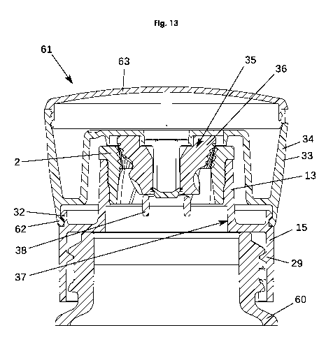
Fig. 13 shows an upper detail from an assembled spice grinder 61. The
spice mill lower part 15 is connected to the spice container 60 by way of
the thread 29. The spice mill upper part 34 has a circumferential snap-on
projection 62, which can be snapped onto the circumferential snap-on
projection 32 of the spice mill lower part 15. The spice mill upper part
34 and the spice mill lower part 15 are rotatably connected to each other.
A cap 63 is removably connected to the spice mill upper part 34.
Date Recue/Date Received 2022-04-06