Note : Les descriptions sont présentées dans la langue officielle dans laquelle elles ont été soumises.
CA 03171471 2022-08-16
WO 2021/168380 PCT/US2021/018940
-1-
SYSTEM AND METHOD FOR GUIDING DIRECTION TO AND TREATING
TARGETS FOR ABNORMAL BIOLOGICAL RHYTHMS
RELATED APPLICATIONS
[0001] This application claims the benefit of the priority of U.S.
Provisional
Application No. 62/979,367, filed February 20, 2020, which is incorporated
herein by
reference in its entirety.
GOVERNMENT RIGHTS
[0002] This invention was made with government support under Grants HL83359
and
HL103800 awarded by the National Institutes of Health (NIH). The government
has certain
rights in the invention.
FIELD OF THE INVENTION
[0003] The present invention relates generally to personalized
identification and
therapy for electrical rhythm disorders, and more particularly to a system and
method for
facilitating personalized treatment.
BACKGROUND OF THE INVENTION
[0004] Medical therapy can be improved by personalization. Accepted
therapies that
work in general may work poorly or not at all in a significant number of
cases. Even in
patients in whom a therapy works, there is often a graded response between
individuals.
Typically, there are few a priori clues that a particular therapy may or may
not work in a
given patient. "Predictors" of response or failure are often based on
observation after the
fact, and current forward-looking predictors provide modest incremental
benefits.
[0005] Current medical strategies explicitly prioritize the majority of
individuals with
a stated condition, and implicitly neglect the statistical minority. An
overlooked but
important issue is that this minority of individuals with the same stated
diagnosis may
respond to a therapy that differs from that used on the majority. While this
minority may
comprise a substantial number of individuals, they may be difficult to
identify (phenotype)
because otherwise they may have already been separated from others into a
different
subcategory.
[0006] There is a need to personalize therapy -- to identify a priori those
patients in
whom a therapy is likely to work, those in whom that therapy is less likely to
work and,
CA 03171471 2022-08-16
WO 2021/168380 PCT/US2021/018940
-2-
thus, tailor therapy for the individual. To meet these objectives,
personalized medicine is
increasingly studied.
[0007] Personalized medicine is frequently espoused for conditions that
result from a
genetic cause ("mechanism"), to phenotype individuals then tailor therapies
accordingly.
Unfortunately, many highly prevalent diseases do not have demonstrable genetic
causes. In
the heart, while genetic cases can be identified for example in coronary
disease due to
inherited familial hypercholesterolemia, or the heart rhythm disorder of
inherited atrial
fibrillation (AF), these cases are the minority. Most heart conditions cases
do not have a
clear genetic cause and are considered to result from multiple factors
(multifactorial).
Indeed, recent studies fail to show genetic abnormalities even in conditions
traditionally
considered genetic, including inherited sudden cardiac arrest in the young,
i.e., Sudden
Arrhythmic Death Syndrome ("SADS").
[0008] Other conditions are partially heritable or have genetic causes with
"incomplete
penetrance." The causes for variability in disease expression or response to
therapy are
unknown and occur, for example, with many therapies for atrial fibrillation.
Such variability
is often ascribed to "environment," and may be represented as the variations
in the cellular
"proteome" or "metabolome," but may be difficult to identify, is often
unproven, and is
rarely used to guide therapy.
[0009] In normal heart rhythms, the sinus node keeps the heart in sinus
rhythm. Heart
rhythm disorders are common and significant causes of morbidity and death
throughout the
world. The most prevalent forms of heart rhythm disorder do not have clear
genetic causes.
[0010] Malfunction of the electrical system, or abnormal propagation of
electrical
waves is a proximate cause of rhythm disorders in the heart, brain and other
organs that
generate electrical impulses (excitable tissue'). Heart rhythm disorders may
be classified
as simple or complex. Simple rhythms have a well-defined circuit that is
stable over time,
as detected by most methods of analysis. Examples include sinus rhythm (SR),
rapid
activation of the normal sinus node causing inappropriate sinus tachycardia
(1ST) or sinus
node reentry, atrial tachycardia (AT) or flutter (AFL), atrio-ventricular
nodal reentry
tachycardia (AVNRT) and atrio-ventricular reciprocating tachycardia (AVRT).
Complex
rhythm disorders have less clear circuits that may change over time such as
atrial fibrillation
(AF), ventricular fibrillation (VF) or polymorphic ventricular tachycardia
(PMVT). Other
rhythm disorders may have simple activation patterns yet may be difficult to
treat because
CA 03171471 2022-08-16
WO 2021/168380 PCT/US2021/018940
-3-
they are transient, such as premature atrial complexes (PACs) or multiple
premature
ventricular complexes (PVCs), or difficult to ablate including atypical forms
of atrial flutter
or ventricular tachycardia (VT).
[0011] Treatment of heart rhythm disorders can be difficult, particularly
for AF, VF
and VT. Pharmacologic therapy for complex rhythm disorder is not optimal, only
40-60%
success in the medium to long term. Ablation for heart rhythm disorders is
increasingly used
and involves maneuvering a sensor/probe to the heart via the blood vessels or
directly at
surgery and delivering energy to a source region to mitigate or eliminate the
rhythm
disorder. Ablation is often difficult for complex rhythm disorders because
conventional
systems to identify and locate a cause (source) are deficient, lacking in
accuracy, precision,
and/or time efficiency, which hinders attempts to deliver energy to eliminate
the disorder.
For instance, success of a single ablation procedure for "paroxysmal" AF,
considered the
simplest form, is only 65% at one and a half years, dropping further over
time. For patients
with more complex, persistent AF, the single procedure success by the "gold
standard"
technique is about 40-50% at year one off medications.
[0012] Several unmet needs exist which, if addressed may improve the
success of
therapy. First, why does the same ablation approach work in some patients yet
not others,
even after multiple attempts? Second, what mechanisms for rhythm disorders are
similar or
differ between individuals, and can they be identified ahead of time? Current
disease
classifications are not ideal for this purpose, since pulmonary vein isolation
fails in 35-50%
of cases of "simple" paroxysmal AF yet works in 40-50% of cases of "advanced"
persistent
AF, both at 1-2 years.
[0013] One proposed mechanism (cause) for AF is localized source regions or
drivers
(termed rotors, sites of rotational activity, repetitive activity or foci)
that may drive
surrounding disorganized activity. It is unclear how best to identify said
sources. It is unclear
why some patients do well after ablation of AF sources, while others do not.
It is unclear
why some individuals have a small number of source regions even in complex AF,
while
others have several. It is undefined if source regions relate to structural
abnormalities such
as low voltage or magnetic resonance imaging abnormalities in some persons but
not others.
[0014] Electrical rhythm disorders are classified by electrical patterns.
This often
involves the introduction of a catheter having a plurality of sensors/probes
into the heart
through blood vessels of the patient. These sensors detect electric activity
of the heart
CA 03171471 2022-08-16
WO 2021/168380 PCT/US2021/018940
-4-
(electrograms) at multiple locations, which has been used to identify causes
of conditions
such as AVRT or AVNRT and define separate therapy even though ECG appearances
are
similar. For simple arrhythmias such as atrial tachycardia, the source can be
identified by
tracing activation back to the earliest location, which is then cauterized
(ablated) to treat the
disorder. This may be challenging even in simple heart rhythm disorders.
[0015] Identifying the source or other target region to treat complex
rhythm disorders
is more challenging. First, signals at each sensor may transition beat-to-beat
in shape and
number of deflections. When a signal in AF has 5, 7, 11 or more deflections,
it is difficult
to identify which are local (i.e., under the sensor), which are from
neighboring regions (i.e.,
far-field activity) or noise. Second, the relative paths of activation between
neighboring
sensor sites may change over time, such as in AF or VF. Overall, this makes it
difficult to
correctly map activity in a complex arrhythmia to identify its source.
[0016] Causes for heart rhythm disorders can been identified by several
methods, yet
none is perfect. It is difficult to identify a priori which patients do and do
not have localized
sources. Some sources identified may be false-positives that do not need
treatment (even if
the sources were validated by optical imaging). Methods to identify sources
are
cumbersome and time consuming to use, including using unwieldy, low-resolution
approaches. Because sources may lie at any location, conventional methods
often map the
entire chamber with multipolar catheters or non-invasively from the body
surface. These
types of global mapping systems are difficult to use and have low and variable
spatial
resolution.
[0017] Further, conventional treatment methods for complex arrhythmias
often require
different tools to map the arrhythmia and distinct tools to deliver therapy,
introducing a
practical disconnect when switching tools. When swapping out systems used to
detect
critical regions for systems to treat those regions, registration errors may
reduce the accuracy
of treating precisely the same site and add time. It is also unclear with
conventional
approaches which source regions, when detected, are the most important. So,
all sources
are commonly treated, although some of these sites may not be critical in any
given patient,
yet this treating of all sources adds time, difficulty and potential risk to
the procedure.
SUMMARY OF THE INVENTION
[0018] The inventive system and method identify and locate source regions
or other
target regions to treat biological rhythm disorders using a personalized
digital medicine
CA 03171471 2022-08-16
WO 2021/168380 PCT/US2021/018940
-5-
approach. The inventive system uses a probe or catheter to detect electrical
signals from
biological tissue, and provides navigational guidance towards source or target
regions for a
rhythm based on the detected electrical signals. The inventive system can then
directly treat
these regions without moving or replacing the probe or catheter. All steps can
be tailored to
an individual automatically based on quantified artificial intelligence-based
algorithms of
how patients with similar data patterns respond to therapy.
[0019] The system and method described herein provide a scheme for
quantitative
personalized therapy via one or a combination of lifestyle changes,
medications, electrical
or mechanical therapy, surgical or minimally invasive ablation, genetic or
stem cell therapy.
The invention disclosed herein is related in part to the subject matter of
International
Application No. PCT/US2019/029004, filed 22.07.2019, the disclosure of which
is
incorporated herein by reference in its entirety.
[0020] One exemplary embodiment uses tools to identify individuals in whom
ablation
therapy for complex rhythm disorders is likely to succeed. These tools may be
non-invasive
or invasive. In patients amenable to ablation therapy, another embodiment
includes a device
to record electrical patterns within the heart and provide directional
guidance to move the
device in three dimensions within the biological organ towards optimal
locations for
therapy. Another embodiment provides the ability to deliver therapy directly
to tissue at
this location.
[0021] In some embodiments, the inventive system provides personalized
diagnosis of
complex rhythm disorders, navigational guidance to target sites of interest
for the rhythm
disorder, and a "single shot" detecting and therapeutic tool for said rhythm
disorders.
[0022] An advantage of the invention is its ability to personalize therapy
by comparing
streams of data from the current individual to streams from other individuals
with similar or
dissimilar profiles, using a digital taxonomy that can be updated using
strategies such as
crowd-sourcing.
[0023] While the examples described herein are directed to disorders of
heart rhythm,
mechanical contraction, or heart failure, other exemplary applications of the
inventive
approach include seizure disorders of the brain, diseases of gastro-intestinal
rhythm such as
irritable bowel syndrome, and bladder disease including detrusor instability.
In general, the
inventive scheme is applicable to chaotic disorders in organs, such as atrial
fibrillation in
the heart or generalized seizures in the brain, as well as simple rhythm
disorders.
CA 03171471 2022-08-16
WO 2021/168380 PCT/US2021/018940
-6-
Accordingly, the examples provided herein are not intended to be limiting. The
personalization aspect of the invention is suited for disorders which are
heterogeneous
syndromes rather than a single disease entity.
[0024] The invention identifies patients in whom targets for therapy are
localized
sources for the rhythm disorder, and patients in whom sources are not present.
An example
of this embodiment is to identify patients with atrial fibrillation who are
likely to benefit
from pulmonary vein isolation ablation alone. Other patients may require
ablation of
localized sources for success. Others may require ablation of other targets
such as those
targeted by Maze surgery. Similarly, the inventive approach can identify
patients with
ventricular tachycardia in whom ablation will or will not be successful.
[0025] Source regions are a subset of targets for a rhythm disorder and are
identified as
patches or regions of organized activity (a) within chaotic disorders such as
atrial fibrillation
in the heart, or (b) from which activation emanates to driver organized
disorders such as
atrial tachycardia or ventricular tachycardia. The inventive scheme uses
analytical tools
including machine learning to detect organized patches. Sources that lie near
regions
targeted by standard therapy, such as pulmonary veins in atrial fibrillation,
a scar isthmus
for ventricular tachycardia or a focal brain lesion for seizure disorders, may
not require
specific further therapy. This information is conveyed to the operator.
[0026] The inventive approach also indicates the most important target
regions for the
rhythm disorder. Without this information, approaches often include treating
all detected
targets in atrial fibrillation, involving detection and therapy of multiple
sources, tissue
regions of scar or complex signals. However, some of these regions may not be
critical, and
this approach can be time consuming, adds difficulty to the procedure, and may
have adverse
effects. The invention thus identifies patients with targets that lie within
regions already
treated by standard therapy, or that are less clear, neither of which require
additional therapy.
[0027] In one embodiment, the invention quantifies the importance of
regions of
interest by quantifying the size or area of organized regions or patches
within disordered
activity such as atrial fibrillation in the heart or generalized tonic/clonic
seizures in the brain.
A hierarchy of targets, from the most dominant to the least, is conveyed to
the operator and
can be used for treatment planning.
[0028] The inventive approach uniquely detects treatment targets for
biological rhythm
disorders such as localized sources without the need for wide-area global
mapping. Global
CA 03171471 2022-08-16
WO 2021/168380 PCT/US2021/018940
-7-
mapping can be cumbersome, may not cover the entire organ, and typically
requires the use
of large probes or catheters that are not ideally suited or unable to deliver
therapy, thus
necessitating use of separate probes for sensing and for therapy. In one
embodiment, the
inventive system uses a mapping spade that is physically large enough to cover
a source
region for simple or complex rhythm disorders, or other targets such as
channels of viable
tissue within fibrotic regions that are small enough to provide high-density
recordings.
[0029] The mapping tool or spade contains a plurality of electrodes that
may number
on the order of 4-256 electrodes. The size of each electrode ranges from 0.1
to 4.0 mm,
with selection of the size depending at least in part on the nature of the
suspected disorder.
For complex rhythms such as atrial fibrillation, a typical electrode ranges in
size from 0.5-
1.0 mm to provide good signal fidelity and detect complex signal types that
may be targets
for therapy. For ventricular tachycardia, a typical electrode ranges in size
from 1-2 mm. For
simple rhythms such as accessory pathway mediated tachycardia, a typical
electrode size
range will be 0.5-1 mm, to discern accessory pathway potentials. Selection of
appropriate
electrode sizes for other applications will be within the level of skill in
the art.
[0030] Spacing between electrodes varies in the range of 0.5-5.0 mm. For
atrial
fibrillation, a typical electrode spacing will be 1-2 mm. For ventricular
tachycardia, a
typical electrode spacing will be 2-4 mm. When very fine detail must be
resolved, a typical
electrode spacing will be 0.5-0.75 mm.
[0031] The size of the spade is personalized to the number of electrodes
and their
spacing, as well as to the type of rhythm and the profile of the patient.
Personalization is
performed using tools such as machine learning calibrated to patients of
similar type and
data (personalized digital phenotypes, PDP). The spade therapy tool contacts
the organ by
conforming to its surface at the same plurality of locations where targets or
sources were
recorded.
[0032] Contact can be enhanced using a variety of compliant materials in
construction,
depending on the intended location within the organ of interest. Nitinol
(nickel titanium
alloy) is one such material, e.g., 34-36 gauge, that can provide sufficient
structural stability
and flexibility. This can be used to construct devices for heating ablation,
such as
radiofrequency or light-emitting diodes, for freezing, such as cryoablation,
or non-thermal
ablation such as pulsed-field ablation. One embodiment uses a conformable
chamber for
mapping and cryoablation, in which the therapy device adheres to tissue during
energy
CA 03171471 2022-08-16
WO 2021/168380 PCT/US2021/018940
-8-
delivery for rapid, accurate and safe ablation. This can be effective for
sources of atrial
fibrillation and atrial tachycardias in the heart, and for seizure foci in the
brain.
[0033] In one embodiment, comprises both detector and treatment elements in
the same
physical device, eliminating the need to use separate tools for each. This
reduces time and
complexity, and may also improve accuracy since locations of desired target
regions do not
have to be stored or registered and then re-found using a separate tool.
[0034] In an embodiment, the invention provides navigational guidance for a
sensor
tool without first collecting data globally using cumbersome large catheters.
The invention
processes data at the current sensor site and calculates the direction in
which to move the
sensor to navigate to the source. This is analogous to automobile global
positioning systems
that use current position to navigate to a desired location, without examining
the entire map
of the earth. This approach enables higher resolution mapping near the target
region than
used currently in wide-area or global mapping systems in the heart.
[0035] The invention personalizes detection and therapy using personal
digital
phenotypes (PDP) of health and disease. PDPs implement "personalized medicine"
or
"precision medicine" digitally, with or without cellular or genomic data. In
general, -omic
data may be unavailable for many individuals, or may contribute less to
diseases of aging
or environment. Input data (e.g., data streams from sensors, stored data from
the electronic
health record, imaging data) are linked to observed labels such as changes in
surrogate
markers, or elimination of the disease with specific therapy. PDPs then
partition inputs into
those associated with health and those associated with deviations (possible
disease) for that
individual. Thus, the invention does not cater just to the statistical
majority of individuals.
[0036] PDPs can combine data streams from various sensors, medical or
consumer
machines separately or in combination (e.g., networked). Data streams may come
from
specialized equipment such as imaging systems, or from novel wearable sensors,
or from
multiple people for crowd-sourced population data. Data from pre-existing
systems may
include data from multiple hospitals in a large digital registry of de-
identified data,
contributing diverse patients, practice patterns and outcome data from
different therapies.
Such approaches may involve blockchain technology to ensure data security,
traceable logs
of data transactions, and data access across multiple physical storage
systems.
[0037] PDPs indicate the relevance of biological and clinical data for the
rhythm
disorder in that individual, which may be unclear to experts, using systems
and methods
CA 03171471 2022-08-16
WO 2021/168380 PCT/US2021/018940
-9-
trained on previously labeled datasets in which a specific therapy was or was
not successful.
This enables the identification of individuals with and without treatable
forms of the
disorder, such as predicting the locations of sources for a biological rhythm
disorder, helping
to guide navigation to said source, predicting the type and size of said
source, and the likely
response to therapy personalized to that individual.
[0038] PDPs are created from a digital taxonomy of patients with a given
disease or
state of health. The taxonomy is constructed from multiple data streams and
stratified by
favorable or unfavorable outcome. Input data can be simple, such as heart
rate, weight and
other readily accessible data, stored elements of the electronic health
record, and/or complex
or sophisticated data which may change dynamically over time (e.g. proteomics
and
biomarkers) or may not change over time (e.g. genetic data). Other phenotypes
may be
clinical labels not tracked by a biomarker, or those with loose statistical
definitions such as
race or ethnic susceptibility. The more detailed and broad, i.e., the
"richer," the population
data elements, the more comprehensive the digital taxonomy.
[0039] Personal digital phenotypes (PDPs) are quantified pathophysiologic
networks,
representing indices from signal processing, associative algorithms, data
clusters including
those from unsupervised machine learning, and supervised networks trained by
labeled
events in similar and dissimilar individuals. Data are partitioned into data
labeled as
'healthful vs disease', or 'responsive to therapy vs non-responsive' analyzed
by one or more
of supervised machine learning, neural networks, unsupervised machine
learning, cluster
analysis, correlation analyses, logistic regression analyses, decision trees,
time domain
analyses, frequency domain analyses, trigonometric transformations, and
logarithmic
transformations.
[0040] The patient's tissue may be heart, nerves that supply regions of the
heart, regions
of the brain that control the nerves, blood vessels that supply regions of the
heart, and tissues
adjacent to the heart. In some embodiments, the disease may be a heart rhythm
disorder
comprising one or more of atrial fibrillation, ventricular fibrillation,
atrial tachycardia, atrial
flutter, polymorphic or monomorphic ventricular tachycardia, ventricular
flutter, or other
electrical disturbance within the heart.
[0041] PDP-based analysis may decipher patterns of heart rhythm disorders
that are
difficult to understand by experts. This is particularly true of complex
disorders which may
include rotational circuits, focal circuits, repetitive patterns, partial
rotational or focal
CA 03171471 2022-08-16
WO 2021/168380 PCT/US2021/018940
-10-
circuits, "random" activity, electrical propagation around areas of scar, or
specific
anatomical sites in an individual. These patterns are difficult to sort out.
The digital
taxonomy links specific patterns with success or failure of drug therapy,
ablation, maze
surgery or other therapies for patients of a given PDP. PDPs for the current
patient, based
on her/his electrical, structural, and clinical data, are 'fit' to the
taxonomy to identify tailored
targets for therapy. This personalized diagnosis, or identification of targets
for therapy, is
novel and based on integration of data across biological scales.
[0042] PDPs for heart rhythm may include data streams of invasive
recordings of
electrical activity (electrograms), blood flow and pressure (hemodynamics),
wall tension
(cardiac contractility and relaxation), and related indices. More detailed
data includes three-
dimensional anatomical and structural abnormalities. Clinical data can be
extracted from
history and physical examination, indices of pathophysiological comorbidities,
blood and
tissue biomarkers, and genetic and cellular makeup of an individual. Non-
invasively,
sensors may record the electrocardiogram, cutaneous measures of nerve
activity, and skin
reflectance. Other types of sensed signals that may be used will be apparent
to one of skill
in the art.
[0043] For complex heart rhythm disorders, inflammation is a likely
contributor yet is
often not included in patient phenotyping. Inflammation may cause some
arrhythmias after
surgery or other conditions such as myocarditis. The link of obesity with
atrial fibrillation
may operate through inflammation in pericardial fat, in turn due to reactive
oxygen species.
Inflammatory findings may have significance which is undefined in any given
person at one
point or over time, or between people. The "inflammosome" may measure the
impact of
inflammation from various pathological insults at the cellular or tissue
level, yet is not
commonly done, may not assess circadian fluctuations, have unclear
relationships to
inflammation for the entire body, and may differ between individuals. It is
thus unclear how
to establish "nomograms" of normal or abnormal states.
[0044] Biomarkers of inflammation are one data stream. A personalized state
of
inflammation may be detected by inflammatory cells in the inflamed organ
system, or in
body fluids such as the blood, urine or cerebrospinal fluid. Byproducts of
inflammation can
be detected by elevated concentrations of biomarkers and cytokines such as
interleukin-6,
nerve growth factor, matrix metalloproteinases. Conversely, several
physiological markers
are abnormal in inflammation (so called "acute phase reactants"). Inflammation
causes, in
CA 03171471 2022-08-16
WO 2021/168380 PCT/US2021/018940
-11-
addition to elevated white cell counts, abnormalities in red cell count, in
hemoglobin
concentration, and in a myriad of acute phase reactants such as C-reactive
protein,
erythrocyte sedimentation rate or white cell counts. In the heart, it is well
known that serum
troponin, a marker of cardiac cell destruction, is an acute phase reactant
whose levels fall
with inflammation (inverse acute phase reactant').
[0045] Arrhythmias in the subgroup of patients with inflammatory causes,
may be
targeted using anti-inflammatory therapy including immunosuppression using
agents such
as tacrolimus, a hitherto unrecognized form of therapy for complex arrhythmias
such as
atrial fibrillation. Other immunosuppression therapy such as steroids or non-
steroidal
agents, or cell therapy may be effective. One rationale is that patients who
receive
immunosuppressive agents after heart transplant rarely develop AF. While
benefit is
attributed to surgical isolation of the pulmonary veins during
transplantation, such isolation
in other populations provides <50-70% freedom from AF. The use of
immunosuppression
for complex rhythm disorders including AF has rarely been used. Digital
taxonomies and
PDPs in the invention will identify individuals with inflammatory mediated
arrhythmias in
whom anti-inflammatory therapy including immunosuppression may be useful.
[0046] For other organ systems, sensed signals from measurable body systems
may
include the central and peripheral nervous system, or the electroencephalogram
(EEG)
measured on the scalp, invasive electrode recordings or peripheral sensors.
Measurements
may also include the respiratory system, skeletal muscles and skin, any
indexes of electrical
signals, hemodynamics, clinical factors, nerve signals, genetic profile,
biomarkers of
metabolic status, and patient movement. Other input data elements may come
from imaging,
nuclear, genetic, laboratory, or other sources, and may also be sensed as a
stream (i.e.,
transmitted to the system), or input as values at specific points in time.
[0047] In general, sensors may be in physical contact with the patient's
body and the
sensor data stream is acquired by one of wired or wireless transmission. The
sensor may be
one or more of an electrode, an optical sensor, a piezoelectric sensor, an
acoustic sensor, an
electrical resistance sensor, a thermal sensor, an accelerometer, a pressure
sensor, a flow
sensor, and an electrochemical sensor.
[0048] Personalized therapy may include modifying at least a portion of the
patient's
tissue by one or more of ablation by energy delivery via contact devices,
energy delivery by
noncontact devices, electrical therapy, thermal therapy, mechanical therapy,
delivery of
CA 03171471 2022-08-16
WO 2021/168380 PCT/US2021/018940
-12-
drug therapy, delivery of immunosuppression, delivery of stem cell therapy,
and delivery of
gene therapy. The method may further include generating updated personal
historical data
with the PDP, the classified one or more qualitative disease classifications,
the personalized
intervention, and an intervention outcome.
[0049] In one aspect, the inventive system includes a processor and a
memory storing
instructions that, when executed by the processor, performs operations
including detecting
bodily signals associated with one or more bodily functions at one or more
sensors
associated with the human body, processing the bodily signals to create one or
more sensed
signatures, processing the signatures using the digital object to determine an
effector
response, delivering one or more effector responses to control a bodily task
and monitoring
said response.
[0050] In another aspect of the invention, an ablation catheter for
treating electrical
rhythm disorders includes an array of sensor electrodes to detect electrical
signals to
determine a location of a target region for treatment. If the catheter is not
optimally
positioned at the target region, a controller uses the detected signals to
guide movement of
the catheter towards the target region. Once proper positioning is
ascertained, the controller
activates ablation components within the catheter to deliver energy to modify
tissue at the
target region.
[0051] In summary, the present invention can identify individuals amenable
to therapy
for complex rhythm disorders, provides directional guidance in three
dimensions to move a
novel sensor device towards optimal locations for therapy, and provide the
ability to deliver
therapy directly to tissue at this location. An embodiment is thus a system
providing
personalized diagnosis of complex rhythm disorders and a 'single shot'
sensor/therapy tool.
Some embodiments, which are not intended to be limiting, include cardiac
applications in
heart rhythm disorders, in coronary artery disease and in heart failure.
[0052] In one aspect of the invention, a system for treating a heart rhythm
disorder
includes a catheter configured to be placed in contact with a tissue surface,
the catheter
comprising a flexible body having a contact surface; an array of sensor
electrodes arranged
within the flexible body, each sensor electrode having a conductive surface
substantially
flush with the contact surface, each sensor electrode configured to detect
electrical signals
from the tissue surface; and one or more treatment elements configured to
deliver energy to
the tissue surface. Each conductor of a plurality of conductors has a distal
end connected to
CA 03171471 2022-08-16
WO 2021/168380 PCT/US2021/018940
-13-
one of a sensor electrode and the one or more treatment element. A controller
in
communication with proximal ends of the plurality of conductors includes a
processor
configured to: receive the detected electrical signals; determine a location
of a target region
of a heart rhythm disorder; determine whether the catheter is optimally
positioned at the
target region, and, if not optimally positioned, to compute directionality to
the target region
and generate movement instructions to move the catheter toward the target
region; and after
determining that the catheter is optimally positioned, generate treatment
signals to activate
the one or more treatment elements to modify tissue in the target region.
In some
embodiments, the flexible layer is generally planar and has a shape selected
from a group
consisting of a rectangle, an ellipse, and an annulus. An elongated hollow
shaft having a
distal end, a proximal end, and a length, is provided with the catheter is
disposed at the distal
end, the controller is disposed at the proximal end, and so that the plurality
of conductors is
retained within and extends the length the shaft, wherein the distal end of
the shaft is
manipulable from the proximal end. A shaft motor may be configured to steer
the distal end
of the shaft in response to movement instructions generated by the controller.
[0053] A
sheath slidably disposed on the shaft has an interior volume configured to
retain the catheter in a folded condition until the catheter is deployed by
sliding the sheath
away from the distal end of the shaft.
[0054] In
some embodiments, the catheter may further include irrigant pores formed in
the flexible body, the irrigant pores in fluid communication with an irrigant
source
associated with the controller, wherein the irrigant source is configured to
deliver irrigant
through the irrigant pores to tissue at the target region in conjunction with
activation of the
array of treatment elements.
[0055] In
some embodiments the one or more treatment elements comprise an array of
ablation electrodes, and wherein a subset of the plurality of conductors
connected to the one
or more treatment elements are electrical conductors configured to deliver
electromagnetic
energy to each ablation electrode. The array of sensor electrodes and the
array of ablation
electrodes may be uniformly distributed around the contact surface, or the
array of ablation
electrodes may be evenly interspersed among the array of sensor electrodes.
[0056] The
processor may be further configured to determine a size of the target region
based on the detected electrical signals, identify one or more ablation
electrodes of the array
CA 03171471 2022-08-16
WO 2021/168380 PCT/US2021/018940
-14-
of ablation electrodes based on at least the size and the location of the
target region; and
activate the identified ablation electrodes.
[0057] The processor may determine the location of the target region by
generating a
directionality map of heart rhythms based on the detected electrical signals,
the
directionality map describing pathways of heart rhythms, generating a guidance
direction in
which to move the flexible body towards the target region, and integrating the
directionality
map to determine the location of the target region. The directionality map can
be generated
by applying a trained machine learning model to the electrical signals,
wherein the machine
learning model is trained on training examples comprising electrical signals
of a human
heart and known target regions of the heart rhythm disorder.
[0058] In some embodiments, each ablation electrode is configured to emit a
distinct
waveform. The controller can be configured to separately address one or more
subsets of
ablation electrodes of the array, and wherein the treatment signals comprise a
first signal to
a first subset of ablation electrodes to emit a first waveform and a second
signal to a second
subset of ablation electrodes to emit a second waveform. The array of sensor
electrodes
comprises at least four electrodes. In some embodiments, the sensor electrodes
can be
configured to deliver ablation energy so that the one or more treatment
elements comprise
the array of sensor electrodes.
[0059] In certain embodiments, the one or more treatment elements comprise
one or
more coolant chambers formed within the flexible body and configured for
retaining a
coolant, and wherein the plurality of conductors comprises a subset of
conductors
configured to direct a coolant fluid from a coolant source to the one or more
coolant
chambers to deliver freezing energy to tissue at the target region. The
flexible body may
have a thermally conductive material incorporated therein to enhance
conduction of freezing
energy to tissue in contact with the contact surface. Alternatively, the one
or more
treatment elements may be an array of cryoablation loci formed within the
flexible body,
and wherein the plurality of conductors comprises a subset of conductors
configured to
direct a coolant fluid from a coolant source to the cryoablation loci in
response to treatment
signals from the controller to deliver freezing energy to tissue at the target
region. In still
other embodiments, the one or more treatment elements may be an array of
targeting
fiducials distributed within the flexible body where the targeting fiducials
are configured
for guiding delivery of ablation energy from one or more external ablation
energy sources.
CA 03171471 2022-08-16
WO 2021/168380 PCT/US2021/018940
-15-
[0060] In still another aspect of the invention, a method for treating a
heart rhythm
disorder includes detecting electrical signals of a heart using the array of
sensor electrodes;
generating a directionality map describing pathways of heart rhythms based on
the detected
electrical signals; integrating the directionality map to determine one of:
(i) a location of a
target region of the heart rhythm disorder in the directionality map, and (ii)
a guidance
direction to the target region of the heart rhythm disorder outside the
directionality map;
determining whether the flexible body is optimally positioned at the target
region according
to the directionality map; and responsive to determining optimal positioning,
activating the
one or more treatment elements of the system to deliver energy to modify
tissue at the
determined location of the target region. Generating the directionality map
may involve
applying a trained machine learning model to the detected electrical signals,
wherein the
machine learning model is trained on training examples comprising electrical
signals of a
human heart and known locations of one or more target regions of a heart
rhythm disorder.
[0061] In some embodiments, the method may further include, responsive to
determining the guidance direction to the target region outside the
directionality map,
steering the device to a subsequent position in the guidance direction to the
target region.
Further, the method may also involve detecting subsequent electrical signals
of the heart
with the plurality of sensing electrodes after steering the device to the
subsequent position;
generating a subsequent directionality map describing pathways of heart
rhythms based on
the subsequent electrical signals; integrating the subsequent directionality
map to determine
one of: (i) the location of a target region of the heart rhythm disorder in
the subsequent
directionality map, and (ii) a subsequent guidance direction to the target
region of the heart
rhythm disorder outside the subsequent directionality map; and responsive to
determining
the subsequent guidance direction to the source region outside the
directionality map,
steering the flexible body to a third position in the subsequent guidance
direction to the
target region. Additionally, the method may include, responsive to determining
the
direction of the target region outside the directionality map, providing a
notification on an
electronic display to move the device in the direction of the target region.
Other approaches
may include one or more of, responsive to determining the location of the
target region,
identifying the one or more ablation components within a threshold proximity
to the location
of the target region, and determining a size of the target region based on the
directionality
CA 03171471 2022-08-16
WO 2021/168380 PCT/US2021/018940
-16-
map, wherein identifying the one or more ablation components is further based
on at least
the size of the target region.
[0062] In still other embodiments, the method may include, responsive to
determining
that the heart rhythm disorder persists: generating a subsequent
directionality map
describing pathways of heart rhythms based on the subsequent electrical
signals; integrating
the subsequent directionality map to determine one of: a location of a second
target region
of the heart rhythm disorder in the subsequent directionality map, and a
guidance direction
to the second target region of the heart rhythm disorder outside the
subsequent directionality
map; and responsive to determining the location of the second target region,
instructing one
or more ablation components of a plurality of ablation components on the
device to modify
tissue at the second target region at the determined location of the second
target region.
BRIEF DESCRIPTION OF THE DRAWINGS
[0063] Some embodiments are illustrated by way of example and not
limitation in the
figures of the accompanying drawings in which:
[0064] FIG. 1 is a block diagram depicting the use of personal digital
phenotypes (PDP)
for clinical purposes in an individual, for comparison against a digital
taxonomy to enable
personalized diagnosis and deliver personalized therapy, in accordance with
one or more
embodiments.
[0065] FIG. 2 illustrates use of personal digital phenotypes in the
inventive system for
the heart, integrating streamed data from the heart or other organs with input
data, with
outputs designed to diagnose or treat regions of the heart, in accordance with
one or more
embodiments.
[0066] FIG. 3 illustrates general use of personal digital phenotypes, to
make a
diagnosis, deliver therapy and track/display therapy response for an
individual, in
accordance with one or more embodiments.
[0067] FIG. 4 is a flow diagram illustrating creation of personal digital
phenotypes
compared to digital taxonomies, in accordance with one or more embodiments.
[0068] FIG. 5 illustrates how personal digital phenotypes are compared to
stored
normal values for an individual, or to population values, to indicate health
or disease, in
accordance with one or more embodiments.
CA 03171471 2022-08-16
WO 2021/168380 PCT/US2021/018940
-17-
[0069] FIG. 6 summarizes the process flow for explaining which data
elements are
critical for demarcating health or disease in the personal digital phenotype,
in accordance
with one or more embodiments.
[0070] FIG. 7 is a flow chart to manage complex arrhythmias based on PDPs,
in
accordance with one or more embodiments.
[0071] FIG. 8 illustrates an embodiment of the system to map heart
arrhythmias, with
a display unit of sensed signals, indicating directional guidance for the
sensor to move
towards a source region of interest, and to indicate when this region has been
reached, in
accordance with one or more embodiments.
[0072] FIG. 9 shows sample regions of interest (ROI) which may be targets
for therapy
for rhythm disorders.
[0073] FIG. 10 provides an overview of directional guidance in the
invention towards
a target region of interest for rhythm disorders using sensed data in that
individual, in
accordance with one or more embodiments.
[0074] FIG. 11A is a flow diagram showing steps for directionality analysis
in
accordance with one or more embodiments.
[0075] FIG. 11B is a flow diagram showing steps for directionality analysis
and
treatment in accordance with one or more embodiments.
[0076] FIG. 12 is a flowchart illustrating a process of treating an
electrical rhythm
disorder in accordance with one or more embodiments.
[0077] FIG. 13 illustrates an exemplary ablation catheter for treating
electrical rhythm
disorders in accordance with one or more embodiments.
[0078] FIG. 14A illustrates examples of alternative spade configurations.
[0079] FIG. 14B illustrates tailoring of the spade configuration to source
or other target
regions in electrical rhythm disorders.
[0080] FIGs. 15A and 15B are perspective and cross-sectional views,
respectively, of
an embodiment of an ablation catheter configured to deliver electromagnetic
energy to
tissue.
[0081] FIGs. 16A and 16B are perspective and cross-sectional views,
respectively, of
an embodiment of an ablation catheter configured to provide irrigant to the
tissue.
CA 03171471 2022-08-16
WO 2021/168380 PCT/US2021/018940
-18-
[0082] FIGs. 17A-17C are perspective and alternative cross-sectional views,
respectively, of an embodiment of an ablation catheter with one or more
cryoablation
components configured to apply freezing energy.
[0083] FIGs. 18A-18B are perspective and cross-sectional views,
respectively, of an
embodiment of an ablation catheter with one or more cryoablation components
configured
to apply freezing energy.
[0084] FIG. 19 is a perspective view of an embodiment of an ablation
catheter with
targeting fiducials.
[0085] FIG. 20 is a block diagram of an exemplary computing environment for
implementing embodiments of the invention.
DETAILED DESCRIPTION OF EXEMPLARY EMBODIMENTS
[0086] For the purposes of this disclosure, the following definitions
apply:
[0087] "Ablation energy" refers to energy used to modify tissue. The tissue
being
modified may correspond to a source region or other target region for an
electrical rhythm
disorder. Modification of the tissue affects one or more electrical rhythms
generated at the
source region. The intended effect in providing ablation energy to the target
region is to
treat an electrical rhythm disorder. Ablation energy includes electromagnetic
energy (e.g.,
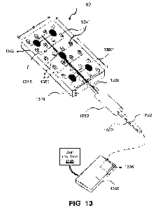
in the form of radio frequency waves administered by ablation electrodes),
freezing energy
(e.g., removal of heat from a tissue with a coolant, generally a rapid removal
or rapid
cooling), some other form of energy capable of modifying tissue.
[0088] "Associative learning" means the process of linking input data with
a
measurable physiology or clinical outcome. Associative learning may be
iterative, enabling
associations to be modified ("learned") based upon patterns of change between
input and
measured output (physiological or clinical endpoints).
[0089] "Biological signal" is a signal is produced by the body and can
reflect one or
more bodily systems. For instance, the heart rate reflects cardiac function,
autonomic tone
and other factors. See also non-biological signal.
[0090] "Biometric signals" mean signals that provide metrics of human
characteristics.
Biometric identifiers can be physiological or behavioral. Physiological
biometrics include,
but are not limited to DNA, fingerprints or palm prints, mouth swabs, tissue
or urine
samples, retinal images, facial recognition, geometry of the hand or foot,
recognition of the
iris or odor/scent of an individual. It can also be applied to signals such as
vital signs, the
CA 03171471 2022-08-16
WO 2021/168380 PCT/US2021/018940
-19-
ECG, the EEG, EMG, and so on. Behavioral biometrics include patterns such as
gait during
walking or typing rhythm. Embodiments of the invention use dynamic patterns of
combined
physiological and behavioral biometrics over time, which adapt to changes in
the individual
and are thus robust to forgery from prior "versions" of a person's signature.
[0091] "Body" means the physical structure of a single-celled organism, a
multi-celled
organism, viruses, and prions. Organisms include animals (such as, but not
limited to,
humans and other mammals), plants, bacteria, etc.
[0092] "Consumer device" means a device that is available directly to a
consumer
without a medical prescription. Historically, such devices typically were not
regulated by a
medical regulatory agency or body, such as the U.S. Food and Drug
Administration or
similar regulatory bodies in other countries, however, more recently, some
devices are FDA
cleared. A Consumer device may include hardware, software, or a combination
thereof It
is typically not a medical device, the latter being defined as an instrument,
apparatus,
implement, machine, contrivance, implant, in vitro reagent, or other similar
or related
article, including a component part, or accessory, which is intended for use
in the diagnosis
of disease or other conditions, or in the cure, mitigation, treatment, or
prevention of disease,
in man or other animals. The definition of a medical device excludes medical
decision
support software.
[0093] "Effector" is a means of performing a task, such as a physical
appliance,
prosthesis, mechanical or electronic device. A physical appliance may enhance
a bodily
function, such as a device to move a limb or move the diaphragm to enhance
breathing
during sleep or a splint to keep the airway open during sleep, or one or more
signals to
stimulate a bodily function, such as electrical stimulation of the phrenic
nerve to enhance
breathing during sleep, or an artificial prosthesis such as a cybernetic limb
or implanted
circuit for the peripheral or central nervous system.
[0094] "Data streams" or "stream(s) of data" mean biological data sensed by
one or
more sensors that can provide real-time or near-real-time information on the
biological
process being sensed. Sensors in the heart may provide streams comprising the
electrocardiogram (ECG), pulse rate, pulse waveform and hence cardiac
hemodynamics.
Other data streams may include cardiac acoustics, including analysis of heart
sounds,
murmurs and sophisticated analyses of hemodynamics related to the heart. Lung
function
may be sensed as chest movement, auscultatory sounds and nerve firing
associated with
CA 03171471 2022-08-16
WO 2021/168380 PCT/US2021/018940
-20-
breathing. Gastrointestinal disease may be sensed as sounds (borborygmi),
movement on
the abdominal wall, and electrical signals related to smooth muscle activity
of the gut.
Central and peripheral nervous system activity may be sensed as nerve activity
on the scalp
(electroencephalogram, EEG), remote from the scalp but still reflecting the
EEG, and from
peripheral nerve firing.
[0095] "Demographics", as used herein, means personal information which may
include, but is not limited to, age, gender, family history of disease,
ethnicity, and presence
of comorbidities and which may be clinically relevant.
[0096] "Digital taxonomy" means a partition of different states of disease
or health
based on quantitative indices. Traditional disease classifications are
qualitative, such as
"atrial fibrillation is more common in the older individuals, those with heart
comorbidities
such as valvular lesions or heart failure, those with metabolic syndrome". A
digital
taxonomy is quantitative, describing an individual's health or risk for a
specific disease in
terms of quantifiable primary and secondary data elements (data vectors). The
likelihood
that a disease entity Di, is present in a specific individual is approximated
by the probability
P(D):
P(D) = (knp(Vn,i))
n
Where m is the number of available data input types, n is the disease being
considered, and
p(V) is the probability that data vector VThi contributes to disease n for
input i, and kii is
a weighting constant for disease n. These elements are integrated in the
digital taxonomy,
which computes specific probabilities that a specific data input contributes
to disease.
Probabilities can be obtained from population data, in which a specific person
is matched to
most-similar individuals in that population. The probability can also be
obtained directly
from this specific individual alone, at times of health (self-reported or
adjudicated) and at
times of disease (self-reported or adjudicated). These calculations can be
performed by
traditional estimating equations but may also by statistical techniques and
machine learning.
A digital taxonomy represents a disease entity stochastically by the aggregate
of
abnormalities in multiple related data inputs. This process is dynamic, since
the equation
reflecting disease will change with additional data inputs, when data changes,
and if the
state of health or disease are updated. The digital taxonomy is well suited to
analyze massive
CA 03171471 2022-08-16
WO 2021/168380 PCT/US2021/018940
-21-
amounts of data from wearable devices in an individual, or massive amounts of
data from
several individual as a crowd-sourced paradigm.
[0097] "Historical data" means stored data, which may include reports from
medical
imaging, e.g., magnetic resonance imaging (MRI), computed tomography (CT),
radiological, or other scans of an organ, data from genetic testing analyses
(e.g., presence of
one or more genomic variants), previously-obtained ECG reports, pathology,
cytology, and
other laboratory reports, as well as clinical demographics such as age,
gender, family history
of disease, and presence of comorbidities. Historical data may further include
additional
personal historical details that could be relevant to generating the PDP, for
example, mental
illness, employment in a high-stress profession, number of pregnancies (in
women),
engaging in high-risk behaviors such as smoking, drug or alcohol abuse, etc.
[0098] "Input data" or "data input(s)" means data not directly sensed by a
physical
component of the system, but data that is utilized by the processing unit in
conjunction with
sensed data to generate the PDP and digital taxonomy. Input data from a data
source may
include streams of data detected using other systems, for example, an external
ECG or EEG
system, clinical, laboratory, pathology, chemical, or other data, or data from
a medical
imaging device, which data is transmitted to the processing unit.
[0099] "Index individual" means a patient or target of a study or
evaluation for whom
a personal digital phenotype may be generated.
[0100] "Machine learning" means a series of analytic methods and algorithms
that can
learn from and make predictions on data by building a model rather than
following static
programming instructions. Machine learning is often classified as a branch of
artificial
intelligence and focuses on the development of computer programs that can
change when
exposed to new data. In the current invention, machine learning is one tool
used to create
the digital network linking sensed data with tasks in each individual.
Mathematically, some
forms of machine learning can be approximated by statistical approaches.
Machine learning
techniques include supervised learning, transfer learning, unsupervised
learning, or
reinforcement learning. Several other classifications may exist, but mostly
embody the
following concepts:
[0101] "Unsupervised Machine learning" includes methods such as cluster
analysis
that may be used to identify internal links between data, potentially such as
the link between
clinical data (diagnosis of atrial fibrillation), family history, data from
physical examination
CA 03171471 2022-08-16
WO 2021/168380 PCT/US2021/018940
-22-
(irregularly irregular pulse), data from sensors, electrical data (irregular
atrial signals on the
ECG), structural imaging data (enlarged left atria), biomarkers, genetic and
tissue data as
available.
[0102] "Supervised Machine Learning" includes methods that can classify a
series of
related or seemingly unrelated inputs into one or more output classes without
explicitly
modeling inputs, i.e., without assuming a potentially incorrect ("biased")
mechanistic
hypothesis.
[0103] "Reinforcement learning" is a form of machine learning related to
psychology,
which focuses on how software agents take actions in a specific environment to
maximize
cumulative reward. Reinforcement learning is often used in game theory,
operations
research, swarm intelligence and genetic algorithms and has other names such
as
approximate dynamic programming. One implementation in machine learning is via
formulation as a Markov Decision Process (MDP). Reinforcement learning differs
from
supervised machine learning in that it does not require matched inputs and
labeled outputs,
and actions that result in sub-optimal rewards are not explicitly corrected
(unlike supervised
learning which may correct suboptimal rewards via e.g., back propagation
algorithms in a
perceptron).
[0104] "Medical device" means an instrument, apparatus, implement, machine,
contrivance, implant, in vitro reagent, or other similar or related article,
including a
component part, or accessory, which is intended for use in the diagnosis of
disease or other
conditions, or in the cure, mitigation, treatment, or prevention of disease,
in man or other
animals.
[0105] "Neural networks" means self-learning networks of interconnected
nodes
modeled loosely after the human brain that can be used to recognize patterns.
Artificial
neural networks can be combined with heuristics, deterministic rules and
detailed databases.
[0106] "Personal digital phenotype" ("PDP") is a digital representation of
health or
disease in an individual, which may or may not include cellular, genomic or
other -omic
data, calibrated to observed response to therapy for an individual. The PDP
for an individual
is matched to those most similar to this individual from a digital taxonomy of
data from a
large group. PDP's thus enable personalized medicine without catering just to
a statistical
majority of individuals. Data elements used to create the PDP may represent
the individual's
health state, weighted by their likely contribution to disease or health for
an individual of
CA 03171471 2022-08-16
WO 2021/168380 PCT/US2021/018940
-23-
similar age, gender and comorbidities. PDPs are matched by algorithmic
analyses which
take into account the calculated or documented probability of impact on health
or disease.
This may use deterministic algorithms or machine learning. For example, a
heart rhythm
phenotype will primarily consider heart rate and electrographic signals
(surface ECG and
intracardiac). Higher mathematical weighting will be given to these data
elements. Data
streams from other (indirect) organ systems may include changes in breathing
rate with heart
rate (i.e., lung sensors), changes in nerve firing with heart rate (i.e.,
nerve function). Other
data elements include abnormal cardiac ejection fraction, location and
presence of structural
abnormalities of the heart. Historical data including age, gender and family
history may
also impact the overall digital personal phenotype.
[0107] "Population data" used herein is a determinant of the accuracy of
the inventive
approach. If the index individual is very different from the reference
population then the
digital taxonomy may not adequately represent this individual. In this case,
data will be
primarily derived from prior data in the individual ideally at times of
adjudicated health and
adjudicated illness. If the reference population is broad but has other
limitations, such as
not being well phenotyped or not having well-labeled data elements, again a
taxonomy will
not be useful. Thus, the ideal data set comprises data streams that are well
labeled, and
comprise individuals that are like the index individual, that can be
partitioned to create a
digital taxonomy. Simply providing 'large' or 'big' data is not sufficient.
[0108] "Sensors" include devices that can detect biological signals from
the body of an
individual. A sensor may be in direct contact with the body or may be remote.
When
applied to a group of individuals, sensors may represent all or part of a
defined population.
Electromagnetic sensors can sense electromagnetic signals relating to the
electromyogram
(EMG), electroencephalogram (EEG), electrocardiogram (ECG), nerve firing or
other
emitter. The term "sensor", especially when describing certain cardiac
applications of the
invention in which electrical information is detected, may be used
interchangeably with
"electrode", "electrode catheter", or "catheter." Electrical sensors can also
detect
bioimpedance, such as conductance across the skin that decreases when the
person perspires,
which may occur during times of sympathetic nervous system predominance.
Sensors can
also detect other chemical changes via current flows. Sensors also include
devices that detect
temperature, such as a thermistor or other thermal detector. Sensors can
detect light such
as changes in the color of reflected light form pulsatile heart activity
CA 03171471 2022-08-16
WO 2021/168380 PCT/US2021/018940
-24-
(photoplesthysmography), changes in peripheral oxygenation (e.g., cyanosis,
anemia,
vasodilation on the skin). Sensors can detect sound via a microphone. This can
be used to
sense sounds from the heart, lungs or other organs. Sensors can detect other
vibrations or
movement via piezoelectric elements. Sensors can detect chemicals directly,
using
specialized sensors for hormones, drugs, bacteria and other elements which are
typically
transduced on the device to an electrical signal. Examples include motion
sensing of chest
wall movement from a breath or heartbeat, chest wall vibrations from certain
types of breath
(e.g., a loud obstructive breathing sound) or heart sound (e.g., a so-called
"thrill" in the
medical literature). Breath sensors can detect movement of the chest wall,
abdomen or other
body parts associated with ventilation, or acoustic data (sound) associated
with breaths, or
oxygenation associated with breathing. Chemical sensors can detect chemical
signals on the
skin or other membranes that reflect body chemistry such as oxygenation and
deoxygenation, metabolic acidosis, stress or other states that will be
familiar to those skilled
in the biochemistry arts. Sensors can also detect images using a camera or
lens requiring
contact from the fingerprint or other body part, or sense movement from
specific muscles,
or sense iris dilation or oscillations from photosensors in a contact lens.
Positional sensors
can identify position of body parts and changes over time (including gait) or
contact sensing
of the position of certain body parts at one point in time or over time (e.g.,
a facial droop, a
facial tick or other idiosyncratic movement),In exemplary embodiments of the
inventive
system, multiple sensors may be used in communication with a central computing
device or
which may form a network linked via BLUETOOTH , WiFiTM, or other protocol to
form
an interne of things (IoT) of biological sensors.
[0109] "Signals" include electronic, electromagnetic, digital or other
information that
can be sensed or acquired. Sensed signals are detected unaltered from their
natural form
(i.e., recorded) with no transformation. Sensed signals are typically
biological signals.
Sensed signals can be detected by humans (e.g., sound, visual, temperature)
but also
machines such as microphones, auditory recorders, cameras, thermometers).
Acquired
signals are detected in a transformed state, such as an ECG recording. Such
signals may be
biological, since cardiac bioelectricity generates the ECG, or non-biological
signals, e.g.,
vibration sensed after application of sonic or ultrasonic energy, or a haptic
signal transduced
from a sensed electrical, sonic or other signal. Signals may be sensed via
physical contact
with a sensor.
CA 03171471 2022-08-16
WO 2021/168380 PCT/US2021/018940
-25-
[0110] "Smart data" means application-specific information acquired from
sources that
can be used to identify and/or act upon normal or abnormal function in an
application. Smart
data is thus different from the term "big data". "Smart data" is tailored to
the individual as
well as being tailored to address the specific task or application ¨ such as
to maintain health
and alertness or detect and treat disease such as sleep disordered breathing.
Tailoring is
based on knowledge of what systems may impact the task in question. Such
knowledge
may be based on physiology, engineering, or other principles. In contrast,
"big data" is
often focused on extremely large datasets for the goal of identifying
statistical patterns or
trends without an individually-tailored link. In machine learning parlance,
smart data may
result from supervised learning of datasets to a known output, while big data
simply speaks
to the volume of data without necessarily implying any knowledge of
significance of
specific datasets.
[0111] "Sources" for a heart rhythm disorder are used herein to indicate
targets for
therapy. In the biological literature, an electrical source or electrical
driver indicates a focus
from which electrical waves emanate outwards, or a reentrant, rotational or
rotor-like circuit
from which activation emanates. These electrical sources drive the rhythm,
such as focal
atrial tachycardia, reentry in ventricular tachycardia or atrial flutter.
Sources may also drive
atrial fibrillation or ventricular flutter or ventricular fibrillation. In the
clinical literature,
different definitions can be applied, and other targets can be identified that
are effective
targets for therapy for a heart rhythm disorder. This includes small channels
of viable tissue
within fibrosis or scar regions of low voltage, regions of complex signals,
regions of high
frequency or rate of activation (including high dominant frequency). Other
electrical targets
include regions of conduction slowing, where contour lines of activation
("isochrones")
crowd which can be detected during sinus rhythm or during more rapid rates
including
during pacing.
[0112] Other biological terms take their standard definitions, such as
heart failure, tidal
volume, sleep apnea, obesity and so on.
[0113] The following description and accompanying figures provide examples
of
applications of the inventive system and method for creating personal digital
phenotypes
(PDP) of health and disease, compared to digital taxonomies, to enable
personalized
strategies to detect regions of interest for biological rhythm disorders and
to treat such
regions of interest. The examples described herein are intended to be
illustrative only. As
CA 03171471 2022-08-16
WO 2021/168380 PCT/US2021/018940
-26-
will be evident to those of skill in the art, additional variations and
combinations may be
formed employing the inventive principles disclosed herein.
[0114] FIG. 1 illustrates an exemplary system to define personal digital
phenotypes
(PDP), compare them to a digital taxonomy to personalize the determination or
health or
disease for an individual, including identification of regions of interest for
electrical rhythm
disorders, then to deliver personalized therapy to such regions. The input
/output (I/O) data
100 includes input signals relating to an individual that have been generated
by one or more
sensors 105 that may be placed external and/or internal to the body. Therapy
devices 110
may be inserted temporarily, such as a treatment catheter, or may be
implanted. Implanted
devices may be inserted expressly to develop/maintain the PDP, to provide
health
maintenance, or to provide continual therapy. Additional inputs 125 include
clinical data,
patient history, physical data, and/or data from electronic medical record
systems. Devices
may communicate by an Internet of Things (IoT), with time-stamped data being
sent to the
input unit 130 via connected or wireless means. The data may be communicated
continuously, near-continuously, real-time, near-real-time or some other
format or
combination of time-acquired signals.
[0115] Several types of sensors may be used, including photosensors,
piezoelectric,
acoustic, electrical resistance, thermal, accelerometers, pressure, flow,
electrochemical, or
other sensor types may be used to measure chemical, light, skin
activity/moisture levels,
pressure, movement, and other parameters relevant Lo development of die PDP.
Selection of
appropriate sensors will be apparent to those of skill in the art. Sensors can
be
interchangeable or fixed in each embodiment. Selection of appropriate
component values
(resistors, capacitors, etc.) and circuit performance characteristics, as well
as addition of
supporting components/circuitry (filters, amplifiers, etc.), will be within
the level of skill in
the art and are not described herein.
[0116] In this exemplary implementation of the system, signals are sensed
from the
heart and may comprise several types. Heart electrical activity can be sensed
directly using
sensors that may be placed on the heart and either in contact or not, sensors
near other body
regions (e.g., esophagus, bronchi and airways, mediastinum), on the body
surface, or not
touching the body, e.g., magnetocardiography, which senses magnetic fields
generated by
heart electrical activity. Sensors may also measure cardiac motion or presence
of ischemic
regions by detecting cardiac motion or the movement of blood through it.
Cardiac motion
CA 03171471 2022-08-16
WO 2021/168380 PCT/US2021/018940
-27-
can be sensed using non-electrical devices e.g., echocardiogram or ultrasound,
from
movement on regions of the body from cardiac motion (ballistic cardiography),
from
electrical impedance change due to alterations in heart chamber volumes. Blood
flow can
be detected using known methods such as Doppler echocardiography, 4D-flow MRI,
or
imaging methods that tag a carrier such as red cells. In various embodiments,
these sensors
can be used separately or in different combinations, and further these
separate or different
combinations can also be used in combination with sensors inserted into the
patient's heart.
Signals may be sensed without physical contact with a sensor. Examples of such
methods
include sensing a heartbeat from emitted electromagnetic fields from the
magnetocardiogram (MCG), or from infrared signatures of cardiac motion. Other
noninvasive sensed signals may include auditory breath sounds or heart sounds
from a
sensitive external microphone. Signals from one or a combination of the
described sensors
are sent via wired or wireless communication to input unit 130.
[0117] Nerve activity is another sensed signal that may be used in the
invention, with
indices such as rate and periodicity of firing, periodicity during the day and
between days,
types and patterns of nerve firing, and spatial distribution of these
measures. In one
embodiment, non-invasive recordings are made from skin patches, but other
embodiments
could use the electroneurogram (ENG) where an electrode is plunged into the
skin to record
from nearby neural tissue. Invasive approaches may be suitable for inpatient
care but less
suited for continuous recordings or consumer applications. Sensors can record
from
different regional nerves if placed in different regions, e.g., electrodes on
the chest may
measure nerve activity related to the heart or its nerves, electrodes on the
neck or head may
measure neural signals including those controlling the heart, or other
locations familiar to
one skilled in the art.
[0118] Lung (pulmonary) function activity is another type of sensed signal,
and may
vary independently of the heart, or as a result of alterations in the heart.
This can be
measured by sensors of breath sound, chest wall movement, oxygenation,
electrical activity
of the phrenic nerve or other sensors.
[0119] A therapy tool or effector 110 enables maintenance of health or
treatment of
disease. This may comprise an electrical stimulator, a thermal stimulator, an
optical
stimulator, a chemical release device (such as for pharmacological therapy
such as an
CA 03171471 2022-08-16
WO 2021/168380 PCT/US2021/018940
-28-
infusion pump), or other stimulator. In one embodiment, this is an ablation
catheter to treat
heart rhythm disorders, passed via vascular access labeled as 120.
[0120] Input data 125 are used for personalization and to reference the
index individual
to population data represented as the disease taxonomy. Input data 125 may
include
demographics, laboratory, chemistry, and image data. For example, some data
inputs for a
person may include "static" stored data, such as date-of-birth (age), gender
and race. Input
data may also include near-real-time data such as patient movement from a
separate device
(e.g., a treadmill, motion sensor in a building), patient ECG or cardiac
information from
separate device (e.g., hospital telemetry, ICU bed monitors), breath sensors,
time-lapse or
time-series data from a separate device (e.g., periodic counts of blood sugar
from a
glucometer), or other data input. Input data can also include indexes of
familial tendency
for disease (Mendelian or non-Mendelian), identifiable genetic loci,
variations in weight, or
susceptibility to toxins such as tobacco or alcohol. Input data are sent via
wired or wireless
connection to input unit 130, with time-stamps.
[0121] The input unit 130 is the data hub, which may be a physical device
or a cloud-
based interface for multiple digital data streams transmitted to it. Data are
time-stamped
and may be kept separate as real-time (streaming) or stored (historical).
[0122] Conventional cloud-based computing/storage 135 may optionally be
used to
store data in addition, or as back-up, to that stored on devices in 105 or
130, and/or to
perform processing of the data. Raw data and analysis results saved or
generated in cloud-
based computing/storage may be separately communicated to external servers
connected via
the Internet. For example, independent recipients may include a research
facility, clinical
trial administrator, or other recipient authorized by the patient.
[0123] A population database 140 provides a reference for data from this
index
individual and may include stored data from a population, time-varying
streamed data,
optional streams which could be crowd-sourced.
[0124] The process controller 145 is programmed to execute algorithms that
include
deterministic formulae as well as neural networks (or other learning machines)
and other
distributed representations to create a personal digital phenotype (PDP) 150
which is
compared to a digital taxonomy 155, classifying data from prior timepoints for
the index
individual based on population database 140. In one embodiment, machine
learning is used
to process input data, develop and learn classifications linking complex
physiological and
CA 03171471 2022-08-16
WO 2021/168380 PCT/US2021/018940
-29-
clinical inputs to outcome at a patient-level (i.e., develop PDPs), compare
these to
quantitative traits in a relevant population (a digital taxonomy of health or
disease), to
prospectively design "optimal" or "personalized" therapy based on specific
individual
characteristics relative to prior observations in that individual, prior
observations in a
comparator population, or mathematically inferred predictions.
[0125] The comparison between PDP 150 and digital taxonomy 155 identifies
and/or
tracks the patient's status, i.e., health or disease. This is done by
computing deviations from
normal in the index individual compared to pre-specified "tolerance limits"
and comparing
to different populations. In an embodiment, this is accomplished by sensing
data streams
from sensors 105 or repeatedly updated data. Data may be input during periods
of
adjudicated "health" for that organ system in that person, or during periods
of adjudicated
"disease". Accumulated data assists future learning to validate PDPs.
Different states may
be detected for altering conditions or grades of health or disease (for
instance, exercise
versus rest) between individuals. This approach differs from current medical
practice, in
which a "population" range for "normal" and "disease" is applied across
multiple patients
with little scope to tailor them to the individual. It is this aspect of the
inventive approach
that provides "personalized medicine" or "precision medicine".
[0126] The status identified through the comparison between PDP 150 and
digital
taxonomy leads to personalize disease and health management 160, which is then
communicated to a diagnose and reporting unit 165 or to guide therapy 170. The
diagnosis/report unit 165 can be a smartphone app, a dedicated device, or an
existing
medical device. Briefly referring to FIG. 3, a custom-designed smartphone app
470 can
show the site of termination from digitally acquired personal data from an
imaging/mapping
system. The sample display panel can show the personal streaming data of an AF
map
created by freely-available online methods playing in a smartphone app. The
display panel
can provide interactive input with the physician to assist in identifying the
critical site for
personalized therapy.
[0127] In one embodiment for use in heart rhythm disorders, the therapy
unit controls
electrical interventions (pacing) or destructive energy (ablation). The
effector device 110
shown in FIG. 1 can be activated to ablate tissue to treat the biological
disorder in a way
that is tailored to personal phenotypes. In alternative embodiments, the
therapy unit may
deliver anti-arrhythmic drugs or anti-inflammatory drugs by an infusion pump,
or gene or
CA 03171471 2022-08-16
WO 2021/168380 PCT/US2021/018940
-30-
stem cell therapy. In another embodiment, therapy can be mechanical constraint
can be
delivered, to ameliorate stretch which can trigger arrhythmias.
[0128] FIG. 2 diagrammatically illustrates an exemplary system that uses
personal
digital phenotypes (PDPs) for an embodiment for treatment of heart rhythm
disorders.
Sensed or stored data 200 may include clinical, laboratory, genetic, or other
data. Examples
of data may include markers of abnormal inflammatory or immunological states
of the body,
and biological markers of atrial fibrillation or ventricular fibrillation.
Direct measures of
inflammatory/immunological equilibrium include, but are not limited to, counts
of
inflammatory cells or concentrations of cytokines in body fluids or in an
affected organ.
Indirect measures of inflammatory/immunological equilibrium represent the
protean impact
of inflammation on various organ systems abnormalities in static and diurnal
measures of
body temperature, body fluid composition, heart rhythm, nerve firing rates,
and the
encephalogram. Additional data may include detection of abnormal neural
control of the
heart and body, enabling modulation of such states to maintain, enhance or
correct
biological rhythms including atrial fibrillation or ventricular fibrillation.
[0129] Input data are evaluated iteratively, compared to normal and
abnormal values
for that individual as well as to populations, and directing interventions and
therapy to
maintain normal equilibrium. In this context, "sensing" signals goes beyond
traditional
collection of raw signals from a detection device, and may include data
generated from other
test procedures, e.g., clinical, laboratory, chemical, etc. As shown in FIG.
2, data 200 may
be generated by devices that sense electrical signals, for example, ECG or
bioimpedance
sensors, combined with a transmitter for communicating the detected signals to
process
controller 285 by wired or wireless transmission. Other repositories or
repository of
streamed or input data obtained from clinical systems, hospital databases,
hospital devices,
or laboratory equipment may also interface with process controller 285.
[0130] The heart 210 can be measured in many ways including ECG electrodes
applied
to the body surface 250. Electrical or electromagnetic signal sensors such as
electrode
catheters in the esophagus 225, electrodes in the right atrium 230, in the
atrial septum or left
atrium 220, or via the great cardiac vein to the coronary sinus (electrodes
235, 240, 245), to
the anterior cardiac vein (electrode 215) that accesses the left or right
ventricle, or directly
to any of these chambers. Sensors 215-245 may also detect activation from
other regions
of the heart.
CA 03171471 2022-08-16
WO 2021/168380 PCT/US2021/018940
-31-
[0131] Cardiac sensors may be external or internal. In some embodiments,
one or more
of the sensors may be external to the patient's heart. For example, sensors
250 detect cardiac
activation via the patient's surface (e.g., electrocardiogram - ECG). Sensors
(not shown)
may detect cardiac activation remotely without contact with the patient (e.g.,
magnetocardiogram). As another example, some sensors may also derive cardiac
activation
information from cardiac motion of a non-electrical sensing device (e.g.,
echocardiogram,
Doppler signals of blood flow, red cell tagged scans). Such sensors can be
classified as
"external sensors" to distinguish them from catheters and electrodes that are
inserted into
the patient's body, into or near the heart (or other organ), i.e., "internal
sensors." In various
embodiments, a variety of external sensors may be used separately or in
different
combinations. Further, these separate or different combinations of external
sensors can also
be used in combination with one or more internal sensors.
[0132] Process controller 285 accepts sensed and input data. In some
embodiments,
process controller 285 is configured to analyze unipolar signals; in other
embodiments, it
analyzes bipolar signals. Process controller 285 uses these sensed data
streams to create a
personal digital phenotype (PDP) for the individual. This is compared to a
digital taxonomy
of relevant previously stored data 265, i.e., the arrhythmia. Process
controller 285 may have
access to population data in population database 262 (also shown in FIG. 1 as
database 140)
to create the digital taxonomy. An intervention is then designed to diagnose
or treat that
individual based on her/his personal digital phenotypes 270.
[0133] In some embodiments, process controller 285 analyzes input
electrical data to
generate map(s) representing source(s) or other target(s) of the heart rhythm
disorder which
can then be displayed on an output device. Population database 262 can be used
to store
intermediate data. Population data 262 can support or aid signal analysis and
can store maps
of potential target regions or source locations for other individuals with
known personal
digital phenotypes as part of the digital taxonomy.
[0134] Internally, process controller 285 typically comprises a digital
signal processor.
It may also include a graphical or other processing unit to execute machine
learning
algorithms or other computations of PDPs to compare against the digital
taxonomy to guide
therapy. Other elements may include traditional computing machines, cloud
computing,
biological computing, or biological-artificial (cybernetic) devices. Referring
briefly to FIG.
CA 03171471 2022-08-16
WO 2021/168380 PCT/US2021/018940
-32-
1, the functions corresponding to input unit 130 and process controller 145
would be among
the computing operations executed within process controller 285.
[0135] Process controller 285 is programmed to implement functional modules
to
generate personalized digital phenotypes of cardiac (rhythm) in the individual
(PDP module
260, which corresponds to element 150 in FIG. 1), match or align the PDP with
digital
taxonomy (taxonomy module 265, corresponding to step 155 in FIG. 1) using data
from
population database 262, to design personalized interventions (design module
270) and
guide delivery of interventions 275.
[0136] Personalized therapy designed in module 270 then delivered at
delivery element
275. Delivery element 275 may employ several effector devices such as a
sense/ablate
multielectrode catheter 290 or an external energy source 295. Other therapy
devices may
include direct electrical outputs, piezoelectrical devices, visual/infrared or
other stimulatory
systems, nerve stimulating electrodes or even virtualized data such as avatars
in a virtual
world interface or elements in a large database that can be queried, as well
as other effector
elements evident to those skilled in the art.
[0137] In the illustrative embodiment, therapy can include pacing. For
example,
instructions generated in module 270 cause the process controller 285 to pace
from pacing
module 255. Pacing can be applied through electrodes 250, 215, 230-245, 290 or
295.
Therapy can be ablation using energy generated by energy generator 280 to
modify tissue.
Internal electrodes (e.g., 215, 230-245), a dedicated ablation catheter 290 or
external energy
source 295 can ablate from energy generator 280. Other forms of energy
include, e.g.,
heating, cooling, ultrasound, laser using appropriate devices controlled by
the process
controller 285 and other modules. Therapy is personalized by delivery to
tissue subtending
an electrical and/or structural target determined by PDPs. Other therapy units
may deliver
anti-arrhythmic drugs using an infusion pump, anti-inflammatory therapy (since
inflammation may be a proximate cause of arrhythmias including fibrillation),
gene or stem
cell therapy. In another embodiment, therapy to deliver mechanical constraint
can be
delivered, to ameliorate stretch which can trigger arrhythmias. Therapy using
external
energy sources 295 can enable a fully non-invasive therapy in which critical
targets for
arrhythmia are identified then treated without invasive strategies.
[0138] FIG. 3 summarizes an exemplary workflow using PDPs to guide and
monitor
therapy. Two forms of input are used: personal data streams 400, which can be
updated
CA 03171471 2022-08-16
WO 2021/168380 PCT/US2021/018940
-33-
over time, and personal stored data 420. Data streams 400 may include sensed
data from
novel or existing sensors 402, such as from wearable devices or consumer
products,
implanted devices 404, invasive sensed signals 406 from existing or dedicated
devices
including minimally invasive products such as a skin, nasal, corneal, buccal,
anal or auditory
probe, from non-invasive sensors 408, which may provide data including motion,
and
temperature from infrared probes, and from transmitted data 410, such as
telemetry from
existing medical equipment.
[0139] Personal stored data 420 may include static data such as imaging
data 422,
ideally including detailed coordinates of regions of scar, fibrosis, ischemia,
reduced
contractile function and potential border zone tissue, laboratory values 424
including serum
biochemistry but also genetic, proteomic, and metabolomic data (when
available);
demographic data 426 and elements from the patient history such as presence of
diabetes
mellitus or hypertension, left atrial size from echocardiography. Additional
personal stored
data may include outcome data such as subjective symptoms of whether a patient
feels well
or not, e.g., "healthy" or "less healthy". Outcome data may also include
objective data such
as acute endpoints of a therapy such as resolution of fever by an antibiotic
or, in an
embodiment, termination of atrial fibrillation by ablation. Objective evidence
may also
include chronic endpoints such as absence of infection or lack of atrial
fibrillation recurrence
on long-term follow-up. The inventive approach may also use combinations of
population
data including population stored data 449, population data streams 452, and
domain
knowledge 455 to define disease taxonomy 446 to identify health and illness,
to partition
data classes based on health-state, and to compare population classes with the
individual.
[0140] Step 440 continuously updates personal digital phenotypes from the
data
streams 400 and stored data 420. This can be done periodically at pre-
determined timepoints
or continuously. Step 443 performs a comparison of the personal digital
phenotype to
externally-determined digital disease taxonomy 446, generated from one or more
of
population stored data 449, population data streams 452, and domain knowledge
455. These
steps are detailed further in FIG. 5.
[0141] In step 460, therapy is tailored to the personal digital phenotype,
and in step 463
the effect of therapy is monitored iteratively using data streams in the
context of already
stored data back in step 440. According to the inventive approach, phenotypes
are based on
the ground truth (label) of whether a patient is ill or not, how ill they are,
and how best to
CA 03171471 2022-08-16
WO 2021/168380 PCT/US2021/018940
-34-
treat them to maintain health or treat illness. These clinically- and
biologically-relevant
operations are included at steps 426, 446-455. The invention acquires novel
data in steps
402-410 to create personalized phenotypes, using data types that may not
always correspond
to data types in stored data in that individual (420-426) or in a comparator
population 446-
455. Such data types are actively acquired by the system so that personal
phenotypes can
better guide therapy and include data types including electrical information
or heart
structure.
[0142] Finally, an interactive interface to report data is provided in step
466. Display
470 provides one example of the many types of data that can be displayed via
an application
on a computer or mobile device. (In the illustrated example, a smart phone is
shown.) An
app implementation has been created for an APPLE iPhone written in Swift via
Xcode.
The image 470 shows sample maps of the arrhythmia with ablation targets, and
may
additionally include one or more of a 3-D heart image, numerical coordinates,
text
descriptions, and quantitative scores. The invention displays features of
personal digital
phenotypes for each individual, with some indication of personalized
management and
therapy decisions. Step 466 generates a smartphone display 470 of these data,
with an
illustration as a smartphone app.
[0143] FIG. 4 provides a more detailed workflow to create PDPs and the
digital
taxonomy, and to compare them. Step 500 takes personal data at time vectors
[T]
comprising one or more timepoints. This includes data streams 502
(corresponding to step
400 in FIG. 3) and personal stored data from a chart 504 similar to personal
stored data 420
in FIG. 3. This data includes measures of biological or clinical significance
such as acute
or chronic outcomes.
[0144] Population data streams 506 (block 452 in FIG. 3) are designed to
make use of
increasingly available datasets. Such streams may include data from
individuals with
similar or different phenotypes relative to the index individual. To provide a
few examples,
this data may include telemetry data from patients in an intensive care ward,
individuals
using a similar wearable device, or soldiers in the field being monitored for
various vital
signs.
[0145] Data from a stored population database 508 (database 449 in FIG. 3)
are
incorporated at a granular level based on similar digital phenotypes. This
differs from the
approach of using traditional statistical associations that tend to be weak,
such as the
CA 03171471 2022-08-16
WO 2021/168380 PCT/US2021/018940
-35-
significant association between AF and obesity which fails to account for thin
individuals
who develop AF or obese individuals who do not. Other granular-level patient
features may
be common between such different patients, such as heart disease or
hypertension in patients
with AF who may be thin or obese. Similarly, atrial scar on imaging is
associated with AF,
yet many individuals with AF have minimal scar while some without AF have
considerable
scar. The numerical matching of patients based on PDP features enhances the
ability of the
invention to tailor therapy for an individual based on known outcomes in
similar patients.
Statistical associations are also performed using multivariate analyses.
[0146] Population data from database 508 are integrated in step 510
(similar to step
446 in FIG. 3) including indices of biological or clinical significance such
as acute or
chronic outcomes which serve as a reference for diagnostic or treatment
utility. The first
step is to featurize the data in step 514 to address the curse of
dimensionality in machine
learning. Feature reduction and feature extraction techniques are well known
in the art and
may vary depending on the type of learning machine that is used, or may be
implemented
using different types or combinations of learning machines or other
algorithms. Possible
operations for feature extraction in step 526 include time domain mathematical
operations
including principal component analyses, averaging, integration, area analysis
and
correlations. Frequency domain analyses include Fourier analyses, wavelet
transforms, and
time-frequency analyses of fundamental frequencies, harmonics or other
frequency
components. Polynomial fitting can also be used to represent data as
polynomial
coefficients. Other generic featurization steps can be used, using widely
available libraries
such as TSFresh (Time Series FeatuRe Extraction). In parallel, population data
are
parameterized in step 534 using similar or different operations.
[0147] Step 518 partitions data into classes that represent a digital
'disease phenotype'
in an individual, or a digital 'disease taxonomy' in a population. The goal is
to better
segregate data ¨ clinical data, but also granular invasive data points and lab
tests ¨ into
partitions of individuals who may appear similar but have different outcomes
from a given
therapy (successful versus unsuccessful). Mathematically, this is done by
constructing
'hyperplanes' in k- parameter space that separate patients who have one
outcome from those
who do not. For the embodiment of arrhythmias, for instance, it remains
unclear why
'paroxysmal' AF in two patients with similar profiles may respond completely
differently
to medications or pulmonary vein ablation. Personal phenotypes code
observations from
CA 03171471 2022-08-16
WO 2021/168380 PCT/US2021/018940
-36-
multiple patients to crowd-sourced partitions ("digital taxonomy") of why AF
in some
patients but not others reflects source or driver regions, structural
abnormalities, neural
components and metabolic comorbidities including obesity. These factors are
not predicted
by the traditional taxonomy of 'paroxysmal' or 'persistent' AF. Using PDPs,
inferential
methods including statistics and machine learning can be used to compare data
to reference
populations to infer best management.
[0148] Step
530 partitions the data as a classification approach. Partitioning can be
performed by many techniques known in the art including, but not limited to,
cluster analysis
and other types of unsupervised learning, or supervised learning methods
including support
vector machines (SVM), logistic regression, naive Bayes, decision trees, or
other
approaches. This partitioning is done for personal data (step 518) and in
parallel population
data (step 538). It should be noted that the partitioning techniques used may
differ for each
step.
[0149]
Cluster analysis, a known unsupervised learning technique, may be used in step
530 to group unlabeled data (e.g., data streams from multiple sensors, input
data, other) into
a collection of items that are "similar" to one cluster but dissimilar from
others, This can
occur even without obvious natural groupings, which is often true in these
applications since
typical phenotypes rarely include clinical data, imaging and continuous data
streams.
Clustering is a powerful tool in this invention, but since the final cluster
pattern depends on
the initial cluster, any ambiguity in identifying the initial cluster patterns
could lead to bias.
The result of the clustering is validated later in step 558.
[0150] Step
546 creates a disease taxonomy from population data using mathematical
models to integrate data streams and stored data from the population (database
508), data
reduction schemes (step 534) and data partitions (step 538). Data from domain
knowledge
database 574 is incorporated to filter mathematical relationships. For
example,
mathematical weighting can be minimized for breast cancer in men, which is
rare, or for AF
in young children, which is rare, while raising mathematical weighting for
aging in men
with coronary disease, which is common. Such traditional domain knowledge is
available
from epidemiological data and population statistics, may also be available
from stored
population data, and is easily translated to mathematical weightings.
[0151] Step
550 creates population digital phenotypes from the disease taxonomy. In
other words, the population digital phenotypes correspond to partitions of
data that form
CA 03171471 2022-08-16
WO 2021/168380 PCT/US2021/018940
-37-
self-consistent disease classes from quantitative data. These may be
clinically obvious, or
clinically obscure ¨ e.g., the link between low magnesium levels and atrial
fibrillation in
some studies. These partitions are each expressed statistically with
confidence intervals and
will be used for comparisons against personal digital phenotypes.
[0152] Step 522 creates a prototype personal digital phenotypes using
personal disease
partitions from step 518 as a base. Step 542 compares the personal digital
phenotype (PDP)
to find a best match population digital phenotype. Candidate personal
phenotypes are given
by a matrix of vectors [Pi in step 554. This comprises multiple data elements,
data types,
some ordinal, some vectorial, and some time dependent.
[0153] in some embodiments, supervised learning is used to refine digital
phenotypes
to predict defined outcomes This involves feature selection, choice of network
architecture,
and appropriate data for training and testing.
[0154] Features will be identified and "tuned" for machine learning to
avoid overfitting
(i.e., poor generalization to future unseen inputs) by deliberately creating
sparse input
"vectors." The invention eliminates redundant features and maximize diversity
of input
features to comprehensively span the underlying input data.
[0155] In one embodiment, features are grouped into three types: (a)
traditional clinical
variables (demographics, comorbidities, biomarkers); (b) electrical signals
(12-lead ECG
and intracardiac signals, of which signal processed parameters can separate AF
phenotypes;
and (c) imaging data including but not limited to 2-D echocardiogram images
(atrial
geometry), 3-D CT data (geometry), 3-D MRI data (fibrotic areas, geometry),
and 3-D
electroanatomic shells of voltage and complex electrogram distribution
generated at EP
study. Clusters (unsupervised learning) can be used for data reduction and can
be used as
additional input features. To understand the significance of features,
filtering and
regularization are used. The inventive approach eliminates variables not
associated with
response classes in training. One approach uses the least absolute shrinkage
and selection
operator (LASSO) that combines advantages of filter and wrapper methods to
minimize
prediction errors and includes variables that contribute to regression
analyses in the final
model.
[0156] Missing data in each feature group will be treated by inserting
(inputting) the:
a) median value; b) predicted value using multiple imputation (a technique
from statistics);
CA 03171471 2022-08-16
WO 2021/168380 PCT/US2021/018940
-38-
c) expected value of that data-type from the literature; and d) constant
signifying missing
data. Each approach will be compared during training of various network
models.
[0157] Formatting of input images and signals. The invention will format
each 3-D
MRI, CT or pseudocolored atrial electroanatomic image (denoting anatomy,
distribution of
specific types of electrogram, e.g., voltage) as 3-D matrices. Time-series
data (12-lead
ECG, bipolar coronary sinus electrograms, unipolar intracardiac electrograms)
will be
processed prior to entering the final network, using feature extraction,
cluster analysis and
pre-processing networks.
[0158] The outcomes used to train the phenotype will vary with each
application. For
the embodiment of heart rhythm disorders, several outcomes may be used to
train
phenotype. One outcome may be high voltage versus low voltage (such as <0.1
mV)
electrogram signals; phenotypes associated with high voltage signals may have
higher
treatment outcomes. Another potential outcome is the presence of clean spatial
maps of AF,
showing consistent rotor or focal sources/drivers; these sites may be
effective treatment
targets. Another desirable outcome is AF termination by drug therapy or
ablation, or long-
term success from drug therapy or ablation. Both can be determined
retrospectively in the
reference population to form the digital taxonomy, and then used to identify
personal
phenotypes that match.
[0159] In one embodiment, supervised learning, typically implemented as an
artificial
neural network ("ANN"), is used to represent the diverse input data and data
streams for the
individual person and population. ANNs typically comprise three elements.
First, a
connection pattern between different layers of nodes (artificial neurons),
forming networks
of variable number of layers each containing multiple nodes per layer.
Implementations can
be as simple as the perceptron, adaptive linear networks, or many other
designs including
deep learning networks. The actual network design can be adaptive to the
specific task and
complexity of the data partitions Second, connection weights between nodes can
be varied
and updated according to multiple learning rules. Third, the activation
function:
determining how each weighted input is converted to its outputs. Typically,
the activation
function Ax) is a composite of other functions g(x), which can, in turn, be
expressed as a
composite of other functions. A non-linear weighted sum may be used, i.e.,/(x)
= K (1i w
g (x), where K (the activation function) may be sigmoidal, hyperbolic or other
function.
CA 03171471 2022-08-16
WO 2021/168380 PCT/US2021/018940
-39-
[0160] A variety of connection patterns, weight and mathematical activation
functions
can be selected, and a variety of updating functions are possible for any
embodiment.
Specific forms are optimal for different disease states and tasks. For
example, the machine
for detecting abnormal heart rate during known atrial fibrillation would be
less complex
than the machine for identifying the site for ablation in atrial fibrillation,
for predicting the
onset of atrial fibrillation, for predicting an exacerbation of heart failure
or for predicting
the onset of coronary ischemia.
[0161] Alternative forms of learning include supervised and unsupervised
methods
including linear logistic regression, support vector machines, decision trees
in "if-then-else"
statements, random forests and k-nearest neighbor analyses. Such formulations
can be
applied independently, or as part of machine learning to augment or create
boundaries
between desired decisions such as the presence (or absence) of sources for
atrial fibrillation
or other associations linking input data with clinical or physiological
outcome for an
individual. Several other forms of machine learning can be applied, and will
be apparent to
an individual skilled in the art.
[0162] Various connection patterns, weighting, node activation function and
updating
schemes can be selected, and specific forms are optimal for different
applications depending
on the data inputs. For instance, imaging inputs and continuous data series
(e.g., electrogram
signals) may be represented by different networks, optimized in an embodiment
with
substantial training data, to each dataset in a given reference population.
Thus, depending
on the application, the invention can be tailored to best represent EEG data,
cardiac and
respiratory signatures, weight, skin impedance, respiratory rate and cardiac
output.
Recurrent neural networks are a data structure which enable analysis of how
the network
achieves its trained conclusions. Manually engineered scalar features (e.g.,
clinical data
elements) can be incorporated using fully connected layers. Featurized time
series (i.e., 12-
lead ECGs or so-called `electrograms' from inside the heart) are processed via
convolutional
neural networks. Standard techniques of dropout, batch normalization, and
hyperparameter
tuning are used to avoid overfitting.
[0163] A feature of machine learning approaches is that they do not need a
priori
knowledge of the specifics of human pathophysiology, but instead learn
patterns of sensed
signals and input data in health and deviations in disease. Thus, they are
well suited for
personalized medicine where current mechanistic hypotheses may be suboptimal.
CA 03171471 2022-08-16
WO 2021/168380 PCT/US2021/018940
-40-
[0164] Step 558 determines which candidate phenotype(s) can be validated,
i.e., which
predicts any hard outcome measure. For AF, this may be sites where ablation
terminated
AF. For coronary disease, this may be clinical constellations that predict
critical stenosis of
epicardial coronary vessels, i.e., an advanced coronary risk score. By
extension, such
candidates can be defined for non-heart diseases. If a match is not achieved,
either the
process of creating the PDP 522 is repeated or the acceptable tolerances X
(block 562) are
widened. If a match is achieved within acceptable tolerances (vector X), the
candidate
becomes the Personal Digital Phenotype P within tolerances X at times T in
step 566. The
phenotype is then used to update the personal historical data for that
individual in database
570, against labeled outcomes used to validate the phenotype. This step is
used to validate
clusters defined in preceding steps as well as for supervised training.
[0165] FIG. 5 illustrates how personal digital phenotypes define the
interface between
health and disease. Step 600 takes each PDP at time T and examines the key
signal types in
the phenotype 603. Mathematical and network analysis 606 are used to identify
abnormalities, compared first to stored personal phenotypes in database 609,
e.g., data from
adjudicated times when the individual was feeling well, or feeling unwell
(symptoms), or
had objective evidence for disease, e.g., an AF episode or not. Step 612
generates a portrait
of personal health or disease based on this analysis.
[0166] Step 615 then determines if the portrait from step 612 represents
health 618 or
not, for the individual, within accepted tolerances. If the result is "out-of-
range" for
healthfulness in the individual, the individual may have entered a potential
disease state in
step 621, and mathematical and network analysis 624 is performed and compared
to
population disease taxonomy 627 to determine if the abnormality for the
individual falls
into "out-of-healthful range" for the population as well. On comparison
against population
fixed and variable definitions of abnormal, defined statistically (step 630),
the invention
now asks if disease is present in step 633. If "yes," then disease 639 is
declared; If not, in
observe step 636, the patient continues under careful surveillance. In either
case, the process
will be repeated for continued monitoring.
[0167] FIG. 6 outlines the explainability analyses for the inventive
method, which aims
to identify data components that are most relevant for a specific disease or
facet of health.
This enables a 'disease-specific PDP'. Explainability also addresses a
criticism that several
data science techniques including machine learning can be a "black box".
Several
CA 03171471 2022-08-16
WO 2021/168380 PCT/US2021/018940
-41-
approaches for explainability are used, including expert domain knowledge to
featurize data
and techniques such as LIME and Grad-CAM as described below. Step 700 analyzes
diverse data types in the PDP. Steps 703, 706 ... 709 consider each data
element in turn
(input data or data streams), to determine which contributes to decision
making for that
disease process or facet of health in steps 712. Several approaches (step 715)
can be used to
determine which component(s) dominated or otherwise contributed to the
classification of
"disease" versus "health".
[0168] Several explainability (or interpretability) techniques can be used,
which will
be familiar to one skilled in the art. One includes the use of attention
layers in recurrent
neural networks. Alternatively, Local Interpretable Model-agnostic
Explanations (LIME)
can be used to explain predictions by approximating an interpretable model.
LIME can be
used for 1-dimensional data such as the ECG or electrical signals from within
the heart
(electrograms), numeric features or images. Another approach is Gradient-
weighted Class
Activation Mapping (Grad-CAM), which identifies the most critical nodes as the
largest
weight multiplied by backpropagated pooled gradient downstream to the final
convolutional
layer. Another embodiment specifies features that should or should not be part
of the model
including spatial domains in images (e.g., size of an atrial driver region, or
ventricular
conduction velocity, or spatial extent of fibrosis in the human heart)
enabling tailored
interpretation to domain electrophysiological "concepts" to ensure that models
do not
converge on irrelevant concepts. An example of this is the Testing with
Concept Activation
Vectors (TCAV) approach. This can examine specific features that should or
should not be
part of the model (e.g., size of AF driver regions), enabling the invention to
tailor
explainability to accepted "concepts". As another example, prediction of an AF
outcome
(e.g., success or failure of ablation) can be tested by an interpretable
model, e.g., presence
of fibrosis near the right atrium. This approach attempts to ensure that
numerical models are
relevant to predictions, and models do not converge on irrelevant concepts.
Explainable
features predicting outcome will thus be identified quantitatively. Clinical
rationale can
subsequently be added 574 via domain knowledge, e.g., the determination that
obesity
predicts negative outcome from ablation or drug therapy, while hair color
predicting positive
outcome may not. Data on populations in whom class IC anti-arrhythmic drug
(AAD) may
be used can also be included.
CA 03171471 2022-08-16
WO 2021/168380 PCT/US2021/018940
-42-
[0169] A feature of the digital taxonomy is to code discordant cases, i.e.,
where the
neural network fails to predict actual outcome. For instance, in a patient
with failed ablation
therapy whose profile includes atrial scar on MM, the invention will be
trained to link the
locations of scar, with locations of ablation lesions, with outcome. One
potential output
from the trained network is that ablation that misses regions of scar may
produce poor
outcome. Domain knowledge (physiological interpretation) is used to provide
plausibility
for any trained network, to ensure mathematically that implausible (or
impossible) links are
not constructed, and hence revise the network. This combined mechanistic/
machine
learning approach is a novel strength of the invention that is often omitted
from machine
learning systems that do not check data representations against known domain
knowledge.
Errors to be avoided include adversarial examples; in image recognition,
applications in
which changing one pixel can alter the classification from "cat" to "dog". The
present
invention prevents such trained networks from being developed in this medical
space where
errors must be minimized.
[0170] Accordingly, the inventive approach directed to developing, testing
and revising
increasingly interpretable data structures. Models will combine statistical
analyses with
expert interpretation of case failures/successes. Simple statistical tests and
linear models
may help to identify correlations between different variables in a system but
may not be able
to capture underlying complexity and nonlinearity of these studied complex
clinical
problems. Decision trees such as CART may allow greater interpretability of
the importance
of each extracted feature from layers of the network. Inputs to decision trees
will be
extracted features from the images and time series signals.
[0171] Another approach in this invention is termed "network clamping." In
step 715,
from a trained baseline "health" version of the network, inputs are deranged
singly or in
batches and the network 712 is rerun to identify which abnormal input
combination causes
the network to most closely recapitulate the "disease state."
[0172] These steps are evaluated in steps 718 to identify the constellation
of data
elements that contribute to deciding on the presence or progression of a
specific disease or
facet of health, i.e., most relevant to this process in step 721. This
"disease-specific PDP"
is used for each specific embodiment and is updated in the personal database
724.
[0173] FIG. 7 illustrates an exemplary workflow for using PDP to manage and
treat
atrial fibrillation. Steps 800, 810 and 820 make up the first triage level,
which personalizes
CA 03171471 2022-08-16
WO 2021/168380 PCT/US2021/018940
-43-
for a specific patient. Steps 830-870 personalize AF mapping, map
interpretation and
ablation.
[0174] Step 800 inputs non-invasive signals for AF. These may comprise ECG
data
from the standard 12-lead ECG, body surface potential mapping (also known as
ECG
imaging, ECGI) which may use up to 200 body surface leads, magnetocardiography
(MCG)
non-invasive structural imaging and other features that can be obtained prior
to invasive
study. Step 810 compares these non-invasive data to elements of the PDP
pertinent to this
arrhythmia in this individual, i.e. the 'arrhythmia PDP' step 805 determined
as outlined in
FIG. 6. Step 820 outputs the decision from this analysis.
[0175] Step 800 provides an option for disease prediction, in which the
inventive
technique identifies phenotypes who do not manifest AF but who may be at risk
due to
specific patterns of structural abnormality marked by low voltage or
potentially abnormal
on delayed enhanced magnetic resonance imaging. In this case, the invention
provides for
AF prediction. Ideal input data in this case may comprise granular imaging
data showing
MRI abnormalities, or granular data on regions of low voltage to enable non-
invasive
detection of structural risk profiles by the network to provide prognosis, or
potentially
targets for therapy. Treatment may include ablation to connect these regions
of scar or
fibrosis.
[0176] Outputs of step 820 are determined quantitatively in an individual
by the non-
invasive data from step 800, the disease-specific PDP (here, for arrhythmia)
and the digital
taxonomy. For the specific embodiment of AF therapy, outputs comprise
lifestyle changes,
drug therapy and ablation. The inventive system quantitatively assigns scores
to each output
using steps outlined above in the sequences shown in FIGs. 4, 5. The lifestyle
change output
is assigned a higher score in a patient with remediable factors such as high
body mass index,
poorly treated diabetes, sedentary lifestyle and excessive alcohol
consumption, etc. The
output of pharmacological therapy will be assigned a higher score in a patient
of older age,
without heart failure and with prior failed AF ablations. These features are
based on
epidemiological data, of which several other features are known to those
skilled in the art,
tailored by the PDP and digital taxonomy for AF. For example, if non-invasive
data show
critical AF regions near the pulmonary veins or in other regions amenable to
ablation, then
ablation is assigned a higher score. If the PDP suggests a good candidate (low
BMI,
paroxysmal AF, no prior ablation) yet non-invasive data show no critical
regions near PVs
CA 03171471 2022-08-16
WO 2021/168380 PCT/US2021/018940
-44-
or in other regions amenable to ablation from the digital taxonomy, then
ablation is assigned
a lower score.
[0177] If step 810 identifies that ablation is likely to work, invasive
recordings in step
830 are engaged. Here the first step is to acquire data from inside the heart,
which is typically
performed during AF using invasive catheters, such as the catheters described
below.
Alternatively, non-invasive data 800 could also be used to provide these data.
Step 840
determines what type of ablation is likely to work. If PDP-tailored ablation
to specific source
regions of interest is not assigned a high score, in step 845 the invention
increases the score
for considering anatomic ablation alone. This would include pulmonary vein
isolation, and,
rarely, other anatomical targets including posterior left atrial wall
isolation, or in specific
patients mitral, roof, intercaval or other lines tailored by the PDP.
[0178] If PDP-tailored ablation is determined in step 840 to have
probability for
success above a pre-determined threshold, steps 850-870 are followed to guide
and deliver
therapy.
[0179] Step 850 considers each region of interest in turn. The PDP-based
analysis of
electrical signals focuses on identifying regions of interest that may be
drivers with
rotational or focal activity, regions of low voltage suggesting scar, or other
regions of
interest. The size of these regions is also identified from intracardiac (with
or without non-
invasive) recordings to tailor the size of the mapping tool and therapy tool
appropriately.
[0180] In some embodiments, the regions are identified one after the other
from a small
mapping catheter that provides high resolution recordings. In step 855, the
signals from the
sensing tool (AF mapping catheter) are analyzed to determine a direction in
which to move
towards a target region of interest (for instance, towards a source).
[0181] Step 860 determines if the AF mapping catheter is overlying a
critical region of
interest. The catheter size is important to assess proper positioning and is
selected using the
PDP to tailor the procedure to the expected size(s) for the patient. If the
mapping catheter
does not overlie the critical region, the process is followed to guide
navigation.
[0182] In step 865, if the mapping tool overlays a critical region, this
region is now
targeted for therapy. In some embodiments, the mapping catheter also includes
the ability
to deliver ablation energy so that this is done seamlessly. In other
embodiments, a separate
ablation tool will need to be deployed.
CA 03171471 2022-08-16
WO 2021/168380 PCT/US2021/018940
-45-
[0183] Step 870 assesses the response to therapy, particularly if the
region of interest
has been eliminated. If not, therapy is repeated.
[0184] The process returns to step 850, navigating to and ablating regions
of interest
until they are all eliminated. The total number of regions treated is
determined in real-time
by the electrical signals obtained from steps 800 and/or, 830 along with the
expected number
of regions based on the PDP.
[0185] In another embodiment, all regions of interest are identified
simultaneously
using global mapping from a basket catheter or inverse solution methods, and
navigation is
applied only to the treatment tool rather than the wide-area mapping catheter.
[0186] FIG. 8 summarizes personalized therapy for an embodiment of ablation
therapy.
On the left side of the figure, sensing tool (mapping catheter) 880 is shown
some distance
from a region of interest. The system analyzes the electrical waves to
determine if the
mapping catheter overlays the region of interest, and in this case determines
that it does not.
The system then provides navigation information to direct the catheter towards
the closest
region of interest. This can be displayed on a portable display 890, such as a
repurposed
smartphone or a smartphone app, or on a dedicated medical display unit. Each
of the display
units will include appropriate data security and privacy safeguards in place.
The navigation
process is iterated, indicated by arrows 892. On the right side of the figure,
the mapping
tool 895 is shown to overlay the region of interest. This is termed the
"treatment position".
Display 898 now indicates "Optimal position, ablate". Ablation can now be
performed if
the mapping catheter includes an ablation tool. If not, a separate ablation
catheter can be
inserted. The process is repeated until the operator determines that
sufficient regions of
interest have been treated. The number of regions to be treated will be
determined by the
PDP for patients of this type relative to the location and size of regions.
[0187] FIG. 9 diagrammatically illustrates several types of regions of
interest (ROI) for
heart rhythm disorders that can be identified and classified by the invention.
These patterns
cover the majority of electrical rhythms. ROI 900 indicates rotational
activation without
fibrillation, which may be seen in micro-reentry from a focal site. ROI 905
corresponds to
rotational activation within fibrillation, which may be seen during atrial
fibrillation or
ventricular fibrillation. It can be detected using the procedures described
herein for
directionality analysis. ROI 920 represents focal activation without
fibrillation and may be
seen in focal tachycardia or extra beats from the atrium or ventricle. Focal
activation in the
CA 03171471 2022-08-16
WO 2021/168380 PCT/US2021/018940
-46-
midst of fibrillation (ROT 925) may be seen during atrial fibrillation or
ventricular
fibrillation and can be detected using directionality analysis. Some
activation patterns may
not show classical electrical rotations (rotors) or focal sources. In this
case, atypical patterns
(ROT 940) may still be targets for therapy, such as partial rotations or
repetitive activations
which may be found in patients with specific comorbidities, e.g., with
advanced disease,
near sites of low voltage or abnormalities on delayed enhancement magnetic
resonance
imaging. Such target patterns may be identified as low voltage zones, or
viable channels of
tissue within regions of low or borderline voltage. When such patterns are
found, the
inventive system will suggest navigation towards this detected target type.
Note that ROIs
900, 920 and 940 cover small regions of tissue and can be covered by a small
mapping tool,
while ROIs 905 and 925 cover larger regions of tissue (in fibrillation) and
may require larger
sensing tools. ROT 960 represents disordered activity with no clear pattern.
If ROT 960 is
identified, no specific navigational guidance is provided and the system
recommends
systematic mapping until another region of interest can be detected.
[0188] FIG. 10 provides an overview of an exemplary directionality analysis
sequence.
In step 1000, complex electrograms (unipolar signals) in AF are obtained. Note
that the
onsets and offsets 1005 of signals in complex arrhythmias are often unclear
and components
may include activation, recovery (repolarization), noise or other features.
The inventive
approach uses numerical methods calibrated to monophasic action potentials
(MAPs) in step
1020. MAPs provide one of the few methods to identify actual activation time
(onset) and
recovery time (offset) in complex rhythms in the human heart. Phase 0 (1022)
of the MAP
indicates onset time, and phase 3 (1024) of the MAP indicates the offset time
during any
electrical rhythm in the tissue. MAP onsets of successive beats are typically
separated by a
duration of 100 ms to 250 ms in atrial fibrillation or ventricular
fibrillation, and 200-500 ms
for atrial tachycardia, atrial flutter or ventricular tachycardia. Conversely,
traditional
electrical signals 1030 in a complex rhythm disorder often include multiple
deflections from
which it can be difficult to discern activation onsets (depolarization) or
offsets
(repolarization). Such signals are traditionally analyzed using features such
as a sharp
inflection point or high slope of depolarization. However, signal 1030 shows
that such rules
often incorrectly label deflections of unclear significance as activation
onset. The inventive
approach employs analytical techniques such as machine learning to identify
activation
onset and offset times from electrograms, calibrated to the ground-truth
annotated in MAP
CA 03171471 2022-08-16
WO 2021/168380 PCT/US2021/018940
-47-
recordings, indicated as line 1028. The analytical tool employed in the
inventive method is
thus able to distinguish onsets ("0"), offsets (also referred to as ends, "E")
and other far-
field noise components ("F") from traditional noisy electrograms, e.g., signal
1030, when
MAPs are no longer present.
[0189] For any given array of electrodes, the trained system can accurately
identify
activation onset and offset, making it possible to accurately map activation
paths in step
1040, even in the case of complex rhythms. The array of electrodes measures
electrical
signals from electrodes over the array. These electrogram comprise many
features including
noise. The machine learning model is applied to each electrogram to identify
the onset and
offset times for each cycle (or beat), and far-field noise. Analysis results
in a sequence of
accurate activation (onset and offset) times at each electrode. These
activation times can be
described as an activation front defined by:
11, * Txy
(I)(x, y, t*) = if t E
0, otherwise
in which the activation front (I) is assigned '1' if there is an activation
time event at that
point (x,y) at rescaled time t*, and is otherwise assigned '0'. Streamlines
are used to track
the flow of activation fronts in time, using spatial gradients over the entire
electrode array
to infer directions of subsequent motion. Within step 1040, different paths
may be
generated, including for example, sequential activation paths 1044 and 1052,
which travel
in opposite directions, and complex path 1048, which is not sequential.
[0190] Analysis of propagation flow in step 1060 provides information on
directionality. The direction of electrical flow in the rhythm can be
calculated across a multi-
sensor array tool 1064. Retracing the direction of the electrical flow
provides a path towards
the source of the rhythm disorder, if detected, or other electrical target. In
step 1080, the
type of source is determined, for example, focal sources 1084 and rotating
sources 1088, to
identify the location from which activation emanates outwards, even during
complex
fibrillatory rhythms, and the direction in which the path would lead.
Obtaining this result
does not require global mapping of the entire chamber, which is often not
possible and even
when possible provides low resolution mapping. The inventive approach of
mapping flow
of conduction over time can be applied to complex rhythms such as
fibrillation, which can
be difficult to interpret by standard vector analysis due to the fact that
waves tend to change
rapidly in space and time.
CA 03171471 2022-08-16
WO 2021/168380 PCT/US2021/018940
-48-
[0191] FIG. 11A illustrates the steps within a sequence for directional
guidance. The
algorithm flow starts at timestep 1120, beginning at t. Neighboring electrodes
are identified
in step 1124 as physically adjacent, with known electrode spacings. Sensing
devices with
neighboring electrodes can take many forms. A few examples shown in the figure
include
a multipole device 1104 -- a high resolution multipolar spade catheter, and a
basket device
1108 -- a multipolar basket catheter. Other multi-electrode devices are known;
selection of
appropriate sensors with known electrode spacings will be apparent to those in
the art. In
step 1128, flow is computed using electrode signals integrated over the
timestep t (shown
previously in FIG. 10). First, the system spatially interpolates the wavefront
0 by electrodes
at known spacing on the array. For each point i along this interpolated
wavefront 0 at time
t, the system searches within a circle for the point j at the next time step
with the most similar
gradient. The system infers that the activation wavefront has traveled from
point i to point j
in this time and marks this flow with an instantaneous flow vector
(propagation over time).
Step 1132 repeats computation of flow (directionality) across regions of the
electrode array
to generate multiple electrograms over windows of 150 ms to create a
collection of
electrograms. As an illustrative example, array 1145 is shown, with the window
arranged
in a pattern corresponding to the positions of the electrodes in a multi-
electrode catheter.
Directionality is integrated in step 1136 over the entire available number of
electrodes on
the array to determine the average direction of electrical flow, indicated by
the large arrow
labeled "Integrated Direction". The dashed lines 1148 indicate flows used to
determine the
average direction, which is capable of describing complex spatiotemporally
changing
fibrillation. Guiding the sensor in reverse from the average direction will
move closer to the
nearest source region or other target region. This approach improves upon the
accuracy that
can be obtained when using a single electrode, which historically has not been
able to find
critical regions of interest for fibrillation. The timestep is incremented (+0
in step 1140 and
the process is repeated for one or more later timesteps for either a
predetermined number of
timesteps or continuously until terminated by the user.
[0192] FIG. 11B provides an overview of the process flow for identification
of possible
arrhythmias. In step 1150, patient data including body signals, e.g.,
intracardiac signals,
are integrated with ECG data and clinical variables such as age, gender. In
step 1165,
multiple mathematical approaches can be used to integrate the patient data
signals, including
correlation coefficients from multivariate regression or supervised machine
learning models
CA 03171471 2022-08-16
WO 2021/168380 PCT/US2021/018940
-49-
such as convolutional neural networks (CNN) or support vector machines (SVM)
trained to
a specific output label of AF termination or long-term outcome during
algorithmic
development. In step 1170, the integrated signals are input into the PDP-based
arrhythmia
predictions to estimate a source region. In step 1175, directionality analysis
is used to guide
the ablation catheter to the target region of interest, for example, a source
for the arrhythmia.
The ablation catheter is then analyzed to determine a ratio (percentage) of
the number of
electrodes that are covered by the region of interest in step 1180. This is
achieved by
determining the area of the sensor that covers the predicted region of
interest. In step 1185,
a determination is made as to whether the area ratio exceeds a predicted
ratio. If so, the
therapy is applied at this site in step 1190. If not, in step 1188, the
catheter is guided toward
a direction, e.g., right, left, anterior, etc. using the available controls,
to move the catheter
toward a position until it meet or exceed the predicted ratio in step 1185.
[0193] Candidates for AF ablation targets include mathematical combinations
of
electrogram features plus comorbidities (e.g., body mass index, diabetes,
hypertension),
demographics (e.g., age, gender, prior ablation or not) and, if available,
genetic, metabolic
and biomarker information. Novel electrogram targets analyze beyond
'traditional' targets.
For instance, studies have suggested that targets such as repetitive patterns,
or transient
rotations or focal patterns, or interrupted rotational or focal patterns, may
be critical to
maintaining arrhythmia in some individuals. This embodiment of the invention
defines
these electrogram features, by determining in individual patients which may be
related to
favorable outcomes. This then becomes a numerical classification within the
digital
taxonomy as data from more individuals is labeled and accumulated.
[0194] Depending on the patient, therapy targets may be rotational or focal
sources/drivers, or other electrical target ¨ regardless of structure.
Intermediate phenotypes
may be present in phenotypes in specific individuals (electrical and
structural, which may
dynamically change with e.g., changes in health status). Again, multiple forms
of electrical
pattern may colocalize with such structural elements, and the invention will
store electrical
signals associated with these sites to update the personal and population
databases. Therapy
may include destruction of tissue by surgical or minimally invasive ablation,
to modulate
via electrical pacing or mechanical pacing, or using gene, stem cell, or drug
therapy.
Medications may include class I agents to decrease atrial conduction velocity,
or class III
agents to prolong refractoriness. AF ablation may not just eliminate tissue,
but target areas
CA 03171471 2022-08-16
WO 2021/168380 PCT/US2021/018940
-50-
bordering fibrosis or areas of electrical vulnerability. Therapy can also be
directed to related
tissue to these regions, their nerve supply, or other modulating biological
systems.
[0195] FIG. 12 is a flowchart illustrating a process 1200 of treating an
electrical rhythm
disorder in accordance with one or more embodiments. The process 1200 is
performed
using a device for sensing and treating electrical rhythm disorders. In some
embodiments,
the device is an ablation catheter such as those described below with
reference to FIGs. 13-
19, a basket catheter, e.g., basket catheter 1108 in FIG. 11A, or other multi-
electrode
catheter. The ablation catheter is configured to perform both sensing of
electrical signals of
a tissue and treatment of electrical rhythm disorders with ablation energy.
The ablation
catheter may provide ablation energy in one or multiple forms, e.g.,
electromagnetic energy,
freezing energy, etc.
[0196] In step 1210, the device detects a plurality of signals of a tissue
using a plurality
of sensing electrodes on an ablation catheter. In step 1220, the detected
electrical signals
from the electrodes are used to generate a directionality map that describes
pathways of
electrical rhythms. The directionality map may be generated by inputting the
detected
electrical signals into a trained machine learning model. In some embodiments,
a supervised
training approach is used in which the learning machine will have been trained
on training
examples comprising electrical signals of a human heart and known locations of
one or more
source or other target regions of a heart rhythm disorder.
[0197] In step 1230, the directionality map is integrated to determine one
of: (a) a
location of a source or other target region of the heart rhythm disorder in
the directionality
map, and (b) a guidance direction to the source or other target region of the
heart rhythm
disorder that lies outside of the directionality map.
[0198] If the model was successful in determining the location of the
source or other
target region, i.e., the directionality map is substantially aligned with the
target, in step 1240,
one or more ablation components on the catheter is activated to modify tissue
at the
determined target location. The number of ablation components to be activated
may be
based on a threshold proximity to the location of the source region for use to
deliver the
ablation energy. The directionality map may be used to determine a size of the
target region
to be ablated and to select the appropriate combination of ablation components
to be used
to modify the determined size of the target. In some embodiments, the ablation
electrodes
may be configured to generate electromagnetic waves that modify tissue at the
target. The
CA 03171471 2022-08-16
WO 2021/168380 PCT/US2021/018940
-51-
ablation energy applied to the electrodes can be modulated to generate a
distinct waveform.
Selection of a particular ablation waveform along with other ablation signal
characteristics
will generally be within the level of skill in the art of the medical
practitioner. Selection
may be assisted by look-up tables or guided by knowledge gained through the
use of a
machine learning model trained on data obtained from population data. The
device may
further vent irrigant from one or more irrigation pores on the device onto the
tissue to
prevent overheating of surrounding tissue or other portions of tissue not
intended to be
modified.
[0199] Irrigation of the electrode grid may be adjusted according to the
number of
electrodes, their size and inter-electrode spacing and anticipated power
delivery and heat
generated during use. The primary goal of the irrigant is to cool tissue and
limit heat rise
during energy delivery. Cooling allows increased power delivery without
approaching
temperature levels that could vaporize tissue or blood with gas formation, or
form char or
clot. Irrigant also directly flushes small clots or clumps of char before they
can aggregate.
Irrigation thus improves safety by reducing the likelihood of these problems.
Appropriate
irrigants may include saline that has similar osmolarity to plasma (i.e.,
"normal saline"),
half of that osmolarity ("half-normal"), higher than that osmolarity
("supernormal").
Alternatives include dextrose (glucose) solutions or other electrolyte
solutions familiar to
those skilled in the art. The flow rate of irrigant is typically in the range
of 2-50 ml/min over
the catheter during ablation. Increasing the rate will increase cooling and
enable greater
power delivery, while reducing flow will lead to greater heating. A typical
flow rate range
for the inventive devices and methods is 5-10 ml/min for the atrium of the
heart, and 15-30
ml/min for treating the ventricle of the heart.
[0200] In still other embodiments, the ablation components may be a
plurality of
cryoablation chambers configured to fill with an appropriate coolant. When the
outer
surface of a coolant-filled chamber is brought into contact with tissue, it
can rapidly cool
the target regions for the heart rhythm disorder. Coolants that can be used in
the cryo-
ablation embodiments include nitrous oxide (N20), with a boiling point of -89
C, carbon
dioxide (CO2), with a boiling point of -79 C, and liquid nitrogen (N2), with a
boiling point
of -188 C. Other refrigerants that may be used will be apparent to those of
skill in the art.
Cardiac and nerve tissue typically die at about -100 C, and so lower
temperatures may
ensure more complete tissue ablation. The drawbacks of very low temperatures,
such as
CA 03171471 2022-08-16
WO 2021/168380 PCT/US2021/018940
-52-
liquid nitrogen, are the technical difficulties of keeping the irrigant
refrigerated, and risks of
unintended damage to surrounding regions, including structures adjacent to the
heart.
[0201] In step 1230, if the process has not determined the actual target
location but has
determined a guidance direction to the target outside of the directionality
map, in step 1250
the catheter is steered toward a subsequent position along the guidance
direction. Once the
catheter has been moved to the next position, step 1210 is repeated to detect
subsequent
electrical signals of the tissue with the plurality of sensing electrodes.
Steps 1220 and 1230
are repeated to successively determine the guidance direction. If the location
is not yet
determined in step 1230, with the catheter continues to be steered
incrementally towards the
source or other target region in step 1250 until an indication is provided
that the target has
been located. In some embodiments, the catheter positioning will be controlled
by a
physician, in which case the system may provide some form of notification,
e.g., a visual
display on a display device, an audible tone, or a combination thereof, to
indicate to the
physician where to move the catheter to follow the guidance direction toward
the target.
[0202] The inventive system may be used to confirm whether the electrical
rhythm
disorder has been successfully treated. Successful treatment entails
correction of the
electrical rhythms and elimination of target regions that would affect the
electrical rhythms.
In optional step 1260, the system may be used to detect electrical signals
within the treated
area using the plurality of sensing electrodes after ablation of the source or
target region.
Upon confirmation of success, the procedure may be terminated by the
physician, or
automatically by the system based on confirmation that there are no further
indicators of the
heart rhythm disorder. The system may be used to determine whether the heart
rhythm
disorder persists based on the subsequent electrical signals. If the disorder
persists, steps
1210-1250 can be repeated to locate a second source or target region that may
be
contributing to the persistent disorder. In some cases, if ablation was not
successful in
treating the target , the disorder may be determined to persist based on
subsequently
captured electrical signals. The system can be used to apply additional
ablation energy to
the same region to ensure successful treatment.
[0203] FIG. 13 illustrates an embodiment of an ablation catheter 1300 for
treating
electrical rhythm disorders. Ablation catheter 1300 combines sensing
functionality and
therapy delivery functionality in one tool which includes a spade 1310, shaft
1320, and
controller 1360. Spade 1310 includes a thin flexible body 1302 that supports
an array of
CA 03171471 2022-08-16
WO 2021/168380 PCT/US2021/018940
-53-
sensing electrodes 1340 for guiding the ablation catheter 1300 to one or more
source or
other target regions. In most embodiments, body 1302 also supports one or more
ablation
components 1350 configured for delivery of a tissue-modifying energy (e.g.,
electromagnetic or thermal), as will be described in further detail below with
reference to
FIGs. 13-. Body 1302 is generally planar in its relaxed (non-deployed)
condition, formed
of a resilient material that is sufficiently flexible to collapse and fold the
body into a
retention volume as well as conform the catheter's contact surface to the
adjacent tissue
surface once deployed. Spade 1310 may further include components such as one
or more
irrigation pores for directing irrigant to the surrounding tissue or imaging.
The proximal
end of spade 1310 is coupled to shaft 1320, which is steerable by controller
1360. Shaft
1320 houses wiring to the various electrodes on the spade 1310 along with
channels for
supplying fluids to the spade 1310, e.g., coolant, irrigant, etc. Shaft 1320
extends
concentrically through a sheath 1330 that has an inner volume configured to
retain spade
1310 when folded. Shaft 1320 may also include one or more contact sensors 1325
for
sensing whether the spade 1310 is in contact with tissue. The controller 1360
is coupled to
the proximal end of shaft 1320. The spade 1310 may attach to shaft 1320 at any
point
around its perimeter. In other words, it need not be symmetrically aligned
with the spade
centerline as illustrated but may be offset from the center.
[0204] Controller 1360 is configured to receive and analyze electrical
signals detected
by the sensing electrodes 1340 to determine a location and/or guidance
direction to a source
or other target region for the arrhythmia. Controller 1360 provides control
signals to the
shaft 1320 to direct movement of spade 1310 in the guidance direction towards
the target
region. Controller 1360 provides signals to ablation components 1350 to modify
the tissue
at the target region. In some embodiments, the functions of the various
components of
ablation catheter 1300 may be otherwise distributed amongst the components. In
additional
embodiments, ablation catheter 1300 includes additional or fewer components
than those
listed herein.
[0205] Spade 1310 is positioned to contact tissue to treat electrical
rhythm disorders.
Typical spade dimensions are 5mm-50mm in width (W), 5mm-50mm in length (L) and
lmm-5mm in thickness (H). In a common embodiment for the heart, dimensions are
25
mm wide, 30 mm long and 2 mm thick. In some embodiments, the spade body 1302
is
formed from a thin, flexible polymer such as silicone, polydimethylsiloxane
(PDMS), or
CA 03171471 2022-08-16
WO 2021/168380 PCT/US2021/018940
-54-
similar biocompatible polymer to allow the spade to be easily collapsed or
folded into the
inner volume of sheath 1330. An exemplary fabrication process would involve a
liquid
polymer being introduced into a mold with the wires 1305, electrodes 1340,
1350 and other
components pre-arranged in the mold. The mold and liquid are then exposed to
appropriate
conditions (e.g., heat, atmosphere, light, etc.) to cure the polymer material
to the desired
finish and flexibility. While the wires may be pre-formed for layout within
the mold, in
some embodiments, the wires 1305 may be interconnects formed using a
conductive paste
or film that is printed or deposited using known patterning techniques, e.g.,
thick film, thin
film, inkjet, or other printing method, into channels in the polymer material
to electrically
connect to the electrodes. To provide a little more detail, the electrodes and
ablation
components positioned within the mold, then a first layer of polymer would be
added to the
mold leaving the connectors on the backs of the components exposed and
partially or fully
cured. Next, the interconnect would be patterned on top of the first polymer
layer. Standard
bonding methods can then be used to connect the printed wires to wires that
extend the
length of shaft 1320 to connect with controller 1360. A second polymer layer
would then
be formed to complete and seal the spade structure. The material should be
sufficiently
durable to tolerate multiple transitions between folding and deployed. The
polymer material
should preferably be appropriate for heating by radiofrequency energy
delivery. In other
embodiments, spade 1310 may be fabricated from a combination or composite of
different
materials, or from the same material that has been treated differently to
impart different
characteristics, for example, varying degrees of flexibility. In some
embodiments, the
thickness of spade 1310 may vary along its length or at different areas of the
spade.
[0206] Sensing electrodes 1340 are arranged in an array within body 1302 so
that they
are flush with or protrude slightly from contact surface 1315. The electrodes
in the array
may be arranged in any number of patterns. For example, sensing electrodes
1340 may be
arranged evenly in a simple rectangular grid as illustrated in FIG. 13, or
other arrangements
(e.g., distribution and/or density) may be used. The number of sensing
electrodes 1340
may range from 4 to 256 electrodes.
[0207] The size and spacing of the sensing electrodes determine the
catheter's
resolution. The electrode sizes may range from 0.1mm to 4.0mm, with selection
of electrode
size depending on the application. For example, small sized sensing electrodes
that are
spaced closely would achieve a high resolution, however, there are tradeoffs
with both small
CA 03171471 2022-08-16
WO 2021/168380 PCT/US2021/018940
-55-
and large electrodes. The smallest practical electrode size is able to
integrate small regions
but may be prone to artifacts (e.g., movement artifacts), while the largest
electrode size is
able to integrate over wider regions but may lose small amplitude signals. For
complex
rhythms such as atrial fibrillation, a typical sensing electrode may range in
size from 0.5 to
1.0 mm to provide good signal fidelity and detect complex signal types that
may be targets
for therapy. For ventricular tachycardia, a typical sensing electrode may
range in size from
1 to 2 mm. For simple rhythms such as accessory pathway mediated tachycardia,
a typical
electrode size range may be 0.5 to 1 mm to discern accessory pathway
potentials. Selection
of appropriate sensing electrode sizes will be within the level of skill in
the art. In some
embodiments, a spade may include a number of differently sized sensing
electrodes
arranged in groups or at specific locations on the spade. The sensing
electrodes 1340 may
also be in a variety of different shapes, e.g., oval, round, square,
rectangular, etc.
[0208] Spacing between sensing electrodes 1340 (measured from the edge to
edge) can
vary in the range of 0.5-5.0 mm. For atrial fibrillation, a typical sensing
electrode spacing
will be 1 to 2 mm. For ventricular tachycardia, a typical electrode spacing
will be 2 to 4
mm. When very fine detail must be resolved, a typical sensing electrode
spacing will be 0.5
to 0.75 mm. In some embodiments, different spacings can be used for different
groupings
of electrodes or at different locations on the space body.
[0209] In the embodiment shown in FIG. 13, ablation components 1350 are
ablation
electrodes arranged in an array within spade body 1302 so that they are flush
with or
protrude slightly from contact surface 1315. The number of ablation electrodes
1350 may
be on the order of 4 to 36 but will depend on the size of the spade. The size
of each ablation
electrode ranges from 0.5 to 4.0 mm. For complex rhythms such as atrial
fibrillation, a
typical ablation electrode ranges in size from 0.5 to 2.0 mm. For ventricular
tachycardia, a
typical ablation electrode ranges in size from 2.0 to 3.0 mm. For simple
rhythms such as
accessory pathway mediated tachycardia, a typical ablation electrode size
range will be 0.5
to 1.0 mm. In some embodiments, a spade may include a number of differently
sized
ablation electrodes arranged in groups or at specific locations on the spade.
The ablation
electrodes 1350 may also be different shapes, e.g., oval, round, square,
rectangular, etc.
[0210] The spacing between ablation electrodes 1350 (measured from the edge
to edge)
can vary in the range of 0.5-10.0 mm. For atrial fibrillation typical ablation
electrode
spacing will be 2.0 to 3.0 mm. For ventricular tachycardia, a typical ablation
electrode
CA 03171471 2022-08-16
WO 2021/168380 PCT/US2021/018940
-56-
spacing will be 3.0 to 6.0 mm. Typically, the density of ablation electrodes
will be lower
than the density for sensing electrodes. In some applications, however, the
density could be
higher for ablation electrodes, depending on the rhythm and chamber in
question.
[0211] When the ablation catheter 1300 is ready to be positioned in an
individual, the
spade 1310 will be in its folded configuration, retained within the interior
volume of sheath
1330 to facilitate insertion into the individual's body, e.g., via vascular
access. Once
ablation catheter 1300 has been guided to the appropriate location, spade 1310
will be
released from sheath 1330 to begin the process of detection and/or treatment
as described
above. The flexibility of spade body 1302 allows spade 1310 to substantially
conform to
the topography of the tissue surface. Optionally, during fabrication,
additional fine gauge
spring wires may have been placed near the spade perimeter to facilitate
unfurling of the
spade once released from the sheath. These spring wires are not be so rigid
that they stiffen
the spade; they merely enhance resilience to the unfolded, i.e., relaxed,
configuration. In
some embodiments, spade 1310 may further include a thermoelectric resistant
material, for
example by embedding such a material within the polymer material used to form
the body
or forming a composite with the body material. Incorporation of electrically-
resistive
material in the spade body can be beneficial to maintaining high fidelity in
the electrical
signals detected by the sensing electrodes 1340. Incorporation of thermally
conductive
material(s) can be useful when modifying the tissue, i.e., electromagnetic
ablation,
cryoablation, etc., to help diffuse or disperse the energy/liquid to avoid
concentrated
delivery immediately at the location of the ablation component. It should be
noted that
while ablation catheter 1300 is described herein as a "spade", it may also be
referred to as a
paddle, a grid, an array, a matrix, or a mesh.
[0212] As noted above, spade 1310 is formed of a thin, flexible,
conformable material,
so that contact surface 1315 contacts and conforms to the tissue. While the
shape of spade
1310 is depicted as rectangular in FIG. 13, this is intended to be
illustrative only and other
shapes may be used. Potential variations may include cutting or rounding the
corners of the
spade to make it easier to pull (or push) the flexible material into the
sheath volume. A few
examples of other shapes are provided in FIG. 14A and discussed in more detail
below.
Selection of other shapes that may facilitate folding/unfolding or other
functions of the
catheter will be readily apparent to those of skill in the art. The size of
spade 1310 also
affects its functionality. For example, a larger spade 1310, though having the
advantage of
CA 03171471 2022-08-16
WO 2021/168380 PCT/US2021/018940
-57-
covering a greater surface area, would represent a bulkier volume and,
therefore, could be
more challenging to deploy and/or extract. A bulkier volume would correspond
to an
increased cross-sectional surface area of the ablation catheter at maximum
width, thus
increasing the opening and pathway dimension required for insertion into the
individual's
body. The spade size can be individualized by the PDP based on the predicted
size of
regions of interest for the individual with known clinical profile. An
exemplary dimensional
range for cardiac arrhythmia applications is on the order of 1.5cm x 1.5cm to
3cm x 3cm
x L). The spade thickness should be sufficient to support the array of sensors
against
the contours of the tissue, while being flexible enough to be collapsed and
folded into the
sheath. An exemplary thickness range would be on the order of 0.10mm to 4.0mm
but may
vary depending on the components and features incorporated into the device. In
one
embodiment, a range of 0.75mm to 1.0mm will be sufficiently flexible to
conform to the
cardiac chamber while providing enough support for the electrode material. In
another
embodiment, a range of 2-3 mm will provide greater structural stability for
use outside the
heart, such as for cardiac surgical applications, or for the ventricle, which
has a greater range
of contractile motion.
[0213] Shaft 1320 is an elongated hollow cylinder or tube formed of semi-
rigid material
with a distal end coupled to spade 1310 and a proximal end coupled to
controller 1360. The
hollow center of shaft 1320 encloses one or more bundles 1322 of wires that
provide
electrical connection to the catheter electrodes, steering wires for
manipulating the catheter,
and, if applicable, liquid tubing, all of which should extend the full length
of the shaft to
provide communication between spade 1310 and controller 1360. Shaft 1320 is
formed
and/or coated to provide a low friction biocompatible outer surface to
facilitate insertion
and removal of the catheter and to reduce risk of damage to the insertion
pathway. The
interior surface of the hollow catheter may also have a low friction coating
to allow free
movement of the wire and tubing bundles 1322 within the center of the shaft.
Appropriate
shafts and shaft materials are known in the art and are widely available
commercially. Shaft
1320 is steerable by controller 1360 to manipulate the spade 1310. Shaft 1320
should be of
sufficient length to extend from an entry point in the individual to the
tissue to be
evaluated/treated. For example, for treatment of cardiac arrhythmias, ablation
catheter 1300
will be inserted through an opening in the individual's leg or groin and
guided through the
femoral artery to the heart. Thus, shaft 1320 should be sufficiently long to
extend the full
CA 03171471 2022-08-16
WO 2021/168380 PCT/US2021/018940
-58-
length from the entry point to the individual's heart. The shaft's partial
rigidity protects the
components housed within the center of the shaft and helps to prevent
deflections in the
shaft that could affect the movement of spade 1310.
[0214] A contact sensor 1325 may be located on the distal end of the shaft
to allow
detection of proper contact of the contact surface of spade 1310 with the
tissue surface. In
other embodiments, the contact sensor 1325 may be located elsewhere on the
ablation
catheter 1300, e.g., at some point on contact surface 1315. A number of
different of sensor
types may be used for contact sensor 1325. For example, contact sensor 1325
can be a
sensor configured to measure force applied to the force sensor. Sufficient
contact with the
tissue surface may be found when the force sensor detects force above a
threshold, e.g., 0.25
Pascals. Another type of sensor that may be used is a proximity sensor capable
of measuring
distance to another surface via capacitive sensing. The change in capacitance
is used to
calculate the distance between the tissue surface and the capacitor in the
proximity sensor.
Sufficient contact with the tissue surface may be found if the measured
distance is within a
threshold distance, e.g., 0.1 millimeters.
[0215] Sheath 1330 is a rigid hollow generally cylindrical body configured
to retain the
spade 1310 in a collapsed or folded configuration. For simplicity, sheath 1330
is illustrated
as a standard cylinder with its base at a right angle to the side, however, in
practical
applications, the sheath body may be beveled, rounded or tapered so that its
outer surface is
smooth and edge-free, minimizing angular components that might catch on
features along
the insertion/extraction pathway. For example, an ovoid or partially-ovoid
shape might be
used. Sheath 1330 is concentrically retained around shaft 1320 and is
configured to slide
longitudinally along shaft 1320 to pull back from the shaft's distal end to
release spade 1310.
Specifically, in its initial position, sheath 1330 retains and covers spade
1310 in a folded
configuration to allow the catheter to be guided to the tissue. Once the
catheter is in place
at the tissue, sheath 1330 is moved away from the shaft's distal end to a
second position,
releasing spade 1310 and allowing it resile into its unfolded configuration.
Sheath 1330
may be connected to controller 1360 via one or more wires that guide the
sheath between
the first position and the second position. In one embodiment, these wires may
be activated
by a micromotor 1326 within the controller. In some embodiments, sheath 1330
may be
displaced using a micromotor built into the shaft and/or sheath that is
connected
electronically to controller 1360 by wires that extend through the shaft to
the controller.
CA 03171471 2022-08-16
WO 2021/168380 PCT/US2021/018940
-59-
[0216] Different organs may have different size recommendations, which may
be
smaller in the brain or for neural mapping for instance and generally will
vary for a given
application and/or biological chamber. For example, it may be important for
ablation in the
heart to encircle a region such as scar, while sensing may be a more uniform
grid. As
another example, it may be important for ablation in the brain to be denser
and focused to
allow deep but narrow penetration, while sensing may cover in a broader area.
Another
constraint on the number of sensing electrodes in a catheter is the size of
the bundle 1322
of wires that can be fit into the shaft. In the example illustrated in FIG.
13, 24 sensing
electrodes 1340 are arranged in a rectangular grid.
[0217] When the sensing electrodes 1340 are in contact with the tissue,
they are capable
of detecting electrical signals of the tissue. Various types of electrodes may
be implemented
for the sensing electrodes 1340. Electrodes can be constructed from
semiconducting or
conductive materials capable of detecting electrical signals from the tissue
surface. Sensing
electrodes 1340 may be individually addressable by the controller and/or may
be arranged
in custom patterns tailored to expected characteristics of arrhythmia regions
of interest.
Multiple electrodes can be formed within one or more continuous sheets of
conducting
substance, e.g., one or more sensor chips, each with multiple sensors, or
discrete sensors
can be individually placed within the spade body 1302. Other types of sensors
can be
included in the catheter, for example, to measure heat (infrared), mechanical
motion
(piezoelectric or other sensors), chemical composition, or other indices that
may have
diagnostic value. The circuitry supporting the sensing electrodes 1340 is
preferably durable
and shock resistant to withstand the energy and pressure that can occur during
ablation. The
electrical signals may be in the form of an electrogram measuring electric
potentials of the
tissue. The electrical signals may at least partially pertain to electrical
rhythms of the tissue.
The placement of the sensing electrodes 1340 is used to create a mapping of
electrical
signals useful for analyzing a location or a guidance direction to a source or
other target
region of an electrical rhythm disorder, e.g., according to the principles
described with
reference to FIGs. 11A & 11B.
[0218] Still referring to FIG. 13, one or more ablation components 1350
deliver
ablation energy to the tissue or aid in delivery of the ablation energy to the
tissue. In one
or more embodiments, ablation components 1350 are disposed within contact
surface 1315
of spade 1310. As illustrated, one possible arrangement involve five ablation
components
CA 03171471 2022-08-16
WO 2021/168380 PCT/US2021/018940
-60-
are arranged with one component at the center and two components each at the
distal and
proximal sides of the contact surface. This pattern is an example only --
other variations,
e.g., with different spacings or patterns, and different numbers of elements,
may be used to
tailor the ablation treatment corresponding to the determined size and/or
shape of a source
or other target region. Activation of one or more of ablation components 1350
is controlled
by controller 1360, allowing each ablation component to be selectively
controlled to provide
an amount of ablation energy selected from a range of ablation energy.
[0219] In some embodiments, ablation components 1350 are ablation
electrodes that
contact the tissue to deliver electromagnetic energy as the ablation energy.
Ablation
electrodes typically have larger contact areas than do sensing electrodes 1340
to deliver
sufficient electromagnetic energy to the surface. The electromagnetic energy
may include
radio frequency electromagnetic waves or may include other frequencies of
electromagnetic
waves. Additional features and variations to the inventive catheters are
described below
with reference to FIGs. 14A ¨ FIG. 19.
[0220] Controller 1360 analyzes the electrical signals received from
sensing electrodes
1340 to determine a location or a guidance direction to a source or other
target region.
Knowledge of the physical position of each sensing electrode 1340 on spade
1310 allows
the controller to determine the location of the electrical signals
corresponding to each
sensing electrode 1340 in relation to the others. Controller 1360 uses the
steps shown in
FIGs. 11A, 11B and 12 to determine one of a location and a guidance direction
to the source
or other target region, then generates signals causing shaft 1320 to move
spade 1310 toward
the target. Upon confirming arrival at the target (e.g., steps 1185, 1230),
controller 1360
instructs delivery of ablation energy to the tissue (steps 1190, 1240).
Controller 1360 may
further interact with other components of the device, i.e., contact sensor
1325, to verify
appropriate tissue contact, and if contact is deemed insufficient, may
instruct movement of
shaft 1320 to properly position spade 1310 for sufficient contact with the
tissue. Following
the sequences shown in FIGs. 11A, 11B and 12, controller 1360 may continue
sensing and
treating other detected target regions, if any, until all have been considered
for treatment.
[0221] In one or more embodiments, ablation catheter 1300 may operate semi-
autonomously. In these embodiments, the controller 1360 performs the
operations of
locating the source or other target region, moving spade 1310 to the target,
treating the target
region by modifying the tissue with ablation components 1350, and concluding
the
CA 03171471 2022-08-16
WO 2021/168380 PCT/US2021/018940
-61-
procedure upon confirmation of successful treatment. In these embodiments,
minimal
intervention by a physician would be required to operate the ablation catheter
1300.
[0222] In other embodiments, the ablation catheter 1300 is operated by a
physician.
Controller 1360 detects and determines the location and/or the guidance
direction to the
source or other target region, then generates one or more indicators (e.g.,
visual and/or
audio) of the location and/or the guidance direction to the physician.
Controller 1360
connects the catheter to the energy source, to an input system and to a visual
display system.
The controller may also connect to a motor 1326 that can directly move or
assist movement
of the catheter. In one embodiment, the physician may physically manipulate
the shaft 1320
to move spade 1310 in the indicated direction. In other embodiments, the
physician may
direct movement of shaft 1320 via a user interface 1365 in communication with
the
controller (and motor 1326), allowing the physician to control movement of the
spade 1310.
Examples of user interfaces that can be included in embodiments include a
handle, joystick,
mouse, or trackball on a computer. In an alternative embodiment, the operator
which can be
the treating physician, can use a virtual, augmented, or mixed reality headset
or virtual,
augmented, or mixed reality goggles to guide movement of the sensing or
treatment tool.
[0223] FIG. 14A illustrates three examples of alternative spade
configurations. Spade
1410 is rectangular in shape with rounded corners, allowing for implementation
of a
rectangular grid of sensing electrodes. This configuration may provide
stability in large
planar structures such as the posterior wall of the left atrium. Spade 1420 is
elliptical in
shape, which may facilitate positioning of the device near extreme curvatures
such as near
the pulmonary veins but includes fewer electrodes near its periphery. Spade
1430 is annular
with sensing electrodes arranged in a ring. This configuration may be most
effective to
"isolate" a region of interest without necessarily ablating it entirely, e.g.,
to minimize energy
delivery and avoid damage to sensitive structures at the center of the region.
These
illustrated spade configurations are provided as examples only. As will be
apparent to those
of skill in the art, other shapes and aspect ratios may be used to tailor the
catheter to the
specific needs of the individual.
[0224] FIG. 14B provides one example of tailoring the spade configuration
to source
or other target regions in electrical rhythm disorders. The example
illustrated is for atrial
fibrillation, which may be sustained by regions of interest of sizes that are
not points, but
rather cover a "large domain" 1440. Alternatively, area 1450 represents
regions of interest
CA 03171471 2022-08-16
WO 2021/168380 PCT/US2021/018940
-62-
that may be focal regions with centrifugal propagation of activation, but may
also be
rotational, partial rotations, repetitive sites and other patterns of the
types illustrated in FIG.
9. Area 1460 (within the dashed lines) depicts the approximate "domain size",
or region of
tissue which must be targeted to treat the biological rhythm disorder. As
illustrated, this is
the domain size of the desired target region which may exhibit low voltage, be
an anatomical
region of interest, or a localized source (focal, rotational, rotor, partial
reentry, repetitive site
in FIG. 9) for atrial fibrillation. Treatment of the biological rhythm is
enabled by matching
spades of various shapes and configurations to target the indicated domain
size, e.g., 1440,
1450, or 1460.
[0225] FIGs. 15A and 15B illustrate an embodiment of the inventive ablation
catheter
configured to apply electromagnetic energy to modify tissue at a target
region. Ablation
catheter 1500 includes a plurality of ablation electrodes 1520 that have a
larger area than
the small high-resolution sensing electrodes 1340 to allow delivery of
electromagnetic
energy for electroporation. The spacing between ablation electrodes 1520 can
be small
enough to ensure substantially contiguous tissue lesions. The ablation
electrodes 1520 may
be interspersed among the sensing electrodes 1340 as shown, or other patterns
may be used.
Ablation electrodes 1520 can be activated en masse, or they can be activated
in one or more
subregions, e.g., by dividing the electrodes into quadrants. The ablation
electrodes 1520
may further be configured to deliver energy in a variety of energy signal
shapes
(waveforms).
[0226] As is known in the art, a waveform describes the electrical energy
signal
generated by the ablation electrodes and with a combination of variable
parameters such as
voltage, current, frequency, wave shape, duration, phase or other wave
properties. For
example, one waveform may be a sine wave having a specified amplitude and
frequency
that is applied for a specified duration, e.g., a few milliseconds. One
example of ablating
with varying waveforms may involve the controller causing a first ablation
electrode to emit
a sine wave having a first specified amplitude, shape, frequency, and
duration, and causing
a second ablation electrode to emit a sawtooth wave having a second specified
amplitude,
shape, frequency, and duration. Various combinations and sequences of
waveforms may be
employed.
[0227] The widthwise cross-sectional view of spade 1510 shown in FIG. 15B
illustrates a single layer of the spade body 1302 with sensing electrodes 1340
and ablation
CA 03171471 2022-08-16
WO 2021/168380 PCT/US2021/018940
-63-
electrodes 1520 positioned with their outer surfaces flush with contact
surface 1515. Each
electrode (sensing electrode 1340 and ablation electrode 1520) is connected
via a
corresponding wire 1530 that extends out of the spade body and continues
through shaft
1320 to controller 1360.
[0228] FIGs. 16A and 16B illustrate an embodiment of an ablation catheter
configured
to provide an irrigant, e.g., normal saline or a chemical buffer, to the
tissue via one or more
irrigation pores 1620. The irrigant cools the tissue surface to avoid
overheating and possible
power shut-down of the ablation electrode tip, allowing deeper energy
delivery. Irrigation
pores 1620 are shown evenly dispersed throughout a spade 1610, however,
different
arrangements may also be used. For example, irrigation pores 1620 may be
concentrated in
the proximity of ablation electrodes 1520. One or more irrigant channels
extend through
shaft 1320 (as part of bundle 1322) to connect the irrigation pores to an
irrigant reservoir
1650 associated with and/or controlled by controller 1360, which controls the
feeding of
irrigant to the pores.
[0229] The widthwise (transverse) cross-sectional view of spade 1610 in
FIG. 16B
shows a single flexible layer with sensing electrodes 1340, ablation
electrodes 1520, and
irrigation pores 1620 arranged on contact surface 1615. In some
implementations, each
irrigation pore may further be controlled by a pore gate 1625 to mechanically
gate flow from
the irrigant channels to irrigation pore 1620. The pore gate(s) 1625 may
further be
controlled by controller 1360. In some embodiments, multiple irrigation pores
1620 may
be controlled by a single pore gate 1625. The pore gate 1625 may further be
controlled to
release irrigant at different flow rates, e.g., periodically releasing 5 mL of
irrigant every few
minutes.
[0230] FIGs. 17A-17C illustrate variations of an embodiment of the
inventive ablation
catheter configured for delivering freezing energy to modify tissue at a
source or other target
region. The ablation catheter 1700 includes a sealed coolant layer 1720
incorporated into
the body of spade 1705. The coolant layer 1720 may be a single coolant chamber
1740
(FIG. 17B), one or more coolant splines 1780 (FIG. 17C), other configurations
of coolant
chambers, etc. The coolant layer 1720 is configured to hold a coolant that
rapidly cools
some or all of the spade 1705. The cooled spade 1705 is useful for providing
freezing energy
to the tissue surface. The coolant chamber 1720 is coupled to controller 1360
via one or
more coolant channels extending through shaft 1320.
CA 03171471 2022-08-16
WO 2021/168380 PCT/US2021/018940
-64-
[0231] The transverse cross-sectional view of spade 1705 shown in FIG. 17B
illustrates
the two layer structure of this embodiment, in which a first layer 1710
retains sensing
electrodes 1340 arranged within contact surface 1715. The second layer 1720 is
defined by
a coolant chamber 1740 enclosed within chamber wall 1745. The material of
which
chamber wall 1745 is formed should have sufficient durability retain its seal
after multiple
exposures to the coolant as well as sufficiently thin and flexible to inflate
with coolant.
When chamber 1740 is deflated, the combined first and second layers must be
sufficiently
flexible to allow spade 1705 to collapse/fold into sheath 1330. The coolant
chamber 1740
is connected to the coolant channels that extend through shaft 1320. One or
more coolant
channels extend through shaft 1320 (as part of bundle 1322) to connect the
coolant chambers
1740 to a coolant reservoir 1750 associated with and/or controlled by
controller 1360, which
controls the feeding of coolant to the chambers (via a pump, not shown). A
thermally
conductive material may be embedded within or otherwise incorporated into
first layer 1710
to enhance thermal transfer of freezing energy from the coolant chamber 1740
to contact
surface 1715.
[0232] FIG. 17C illustrates an alternative transverse cross-sectional view
of a spade
1705 in which second layer 1720 includes one or more coolant splines 1780
rather than the
single coolant chamber 1740 of FIG. 17B. Sensing electrodes 1340 are arranged
within
contact surface 1715 of first layer 1710. Coolant splines 1780 are configured
to fill with
coolant to rapidly cool portions of contact surface 1715 corresponding to the
spline. In some
embodiments, coolant splines 1780 may be of a similar size and shape. As
illustrated in
FIG. 17C, coolant splines 1780 extend longitudinally within spade 1705,
however, different
configurations, e.g., sizes and shapes, may be used. Controller 1360 may
separately deliver
freezing energy to selected splines to target regions of the tissue to be
treated. For example,
the middle two coolant splines may be filled with coolant to cooling only the
middle third
portion of the spade. As described above, first layer 1710 may incorporate a
thermally
conductive material.
[0233] FIGs 18A and 18B illustrate another embodiment of the inventive
ablation
catheter for effecting cryoablation. Ablation catheter 1800 comprises a spade
1810 with
sensing electrodes 1340 and one or more cryoablation loci 1820 located on
contact surface
1815 to deliver freezing energy to a tissue surface.
CA 03171471 2022-08-16
WO 2021/168380 PCT/US2021/018940
-65-
[0234] The widthwise cross-sectional view shown in FIG. 18B illustrates the
two layer
configuration of spade 1810. First layer 1830 that supports sensing electrodes
1340 and
cryoablation loci 1820 within contact surface 1815. Second layer 1840 encloses
coolant
chamber 1850, which is similar in construction to coolant chamber 1740 of
spade 1705. The
cryoablation loci 1820 are channels that extend partially through first layer
1830 and
connect to coolant chamber 1850. These channels are sealed at contact surface
1815 such
that coolant is not released from the device. The cryoablation loci 1820 are
configured to
be filled with coolant from the coolant chamber 1850. When filled with
coolant, the area
on contact surface 1815 corresponding to the cryoablation loci 1820 are
rapidly cooled to
provide the freezing energy to the adjacent tissue. In some embodiments, a
cryoablation
loci 1820 has a locus gate 1825 to selectively allow coolant to flow from
coolant chamber
1850 to the cryoablation locus 1820. The locus gate 1825 may be controlled by
controller
1360. In other embodiments, the cryoablation loci 1820 may be connected
directly to a
coolant channel without a coolant chamber 1850. The tradeoff being that having
the coolant
chamber 1850 increases a maximum amount of freezing energy, i.e., affecting a
speed of
cooling, but sacrificing on thickness of the spade 1810. One or more coolant
channels
extend through shaft 1320 (as part of bundle 1322) to connect the coolant loci
1820 to a
coolant reservoir 1850 associated with and/or controlled by controller 1360,
which controls
the feeding of coolant to the loci (via a pump, not shown).
[0235] FIG. 19 illustrates yet another embodiment of the inventive ablation
catheter in
which targeting fiducials are included to facilitate treatment via external
energy sources.
Ablation catheter 1900 includes a plurality of targeting fiducials 1920
positioned within
spade 1910 for guiding delivery of ablation energy from one or more external
ablation
components. The targeting fiducials 1920 can be visualized using X-ray
fluoroscopy or
detected by other techniques as are known in the art. Once a treatment target
for a heart
rhythm is detected in this embodiment, energy can be delivered from an
external source of
X-rays or other electromagnetic radiation, or proton beams. Such energy
sources may be
similar to those used for radiotherapy for tumors. The spacing between
targeting fiducials
1920 is small enough to ensure contiguous tissue lesions. Fiducials can be
targeted en
masse, or they can be targeted in subregions corresponding to sensor
quadrants.
[0236] FIG. 20 diagrammatically illustrates a computer system that can be
used to
implement the inventive method, as may be incorporated into various devices,
such as a
CA 03171471 2022-08-16
WO 2021/168380 PCT/US2021/018940
-66-
personal computer (PC), a tablet PC, a personal digital assistant (PDA), a
mobile device, a
palmtop computer, a laptop computer, a desktop computer, a communications
device, a
control system, a web appliance, or any other machine capable of executing a
set of
instructions (sequentially or otherwise) that specify actions to be taken by
that machine.
Further, while a single computer system 2300 is illustrated, the term "system"
should also
be taken to include any collection of systems or sub-systems that can
individually or jointly
execute a set, or multiple sets, of instructions to perform one or more
computing functions.
[0237] As illustrated in FIG. 20, the computer system 2300 may include a
computer
processor 2302, e.g., a central processing unit (CPU), a graphics-processing
unit (GPU), or
both. The computer system may include a main memory 2304 and a static memory
2306
that can communicate with each other via a bus 2326. As shown, the computer
system 2300
may further include a video display unit 2310, such as a liquid crystal
display (LCD), an
organic light emitting diode (OLED), a flat panel display, a solid state
display, or a cathode
ray tube (CRT). Additionally, the computer system 2300 may include an input
device 2312,
such as a keyboard, and a cursor control device 2314, such as a mouse. The
computer
system 2300 can also include a drive unit 2316, a signal generation device
2322, such as a
speaker or remote control, and a network interface device 2308.
[0238] In some embodiments, the drive unit 2316 may include a computer-
readable
medium 2318 in which one or more sets of instructions 2320, e.g., software,
are stored. The
drive unit 2316 may be a disk drive, a thumb drive (USB flash drive), or other
storage
device. Further, the instructions 2320 may embody one or more of the methods
or logic as
described herein. In a particular embodiment, the instructions 2320 may reside
completely,
or at least partially, within the main memory 2304, the static memory 2306,
and/or within
the processor 2302 during execution by the computer system 2300. The main
memory 2304
and the processor 2302 also may include computer-readable media.
[0239] In an alternative embodiment, dedicated hardware implementations,
such as
application specific integrated circuits (ASICs), programmable logic arrays
(PLAs) and
other hardware devices, can be constructed to implement one or more of the
methods
described herein. Applications that may include the apparatus and systems of
various
embodiments can broadly include a variety of electronic and computer systems.
One or
more embodiments described herein may implement functions using two or more
specific
interconnected hardware modules or devices with related control and data
signals that can
CA 03171471 2022-08-16
WO 2021/168380 PCT/US2021/018940
-67-
be communicated between and through the modules, or as portions of an
application-
specific integrated circuit. Accordingly, the present system encompasses
software,
firmware, and hardware implementations.
[0240] In accordance with various embodiments, the methods described herein
may be
implemented by software programs tangibly embodied in a processor-readable
medium and
may be executed by a processor. Further, in an exemplary, non-limited
embodiment,
implementations can include distributed processing, component/object
distributed
processing, and parallel processing. Alternatively, virtual computer system
processing can
be constructed to implement one or more of the methods or functionality as
described herein.
[0241] It is also contemplated that a computer-readable medium includes
instructions
2320 or receives and executes instructions 2320 responsive to a propagated
signal, so that a
device connected to a network 2324 can communicate voice, video or data over
the network
2324. Further, the instructions 2320 may be transmitted or received over the
network 2324
via the network interface device 2308.
[0242] The foregoing describes embodiments of a system and method to create
personalized digital phenotypes of disease, which are compared to digital
taxonomies to
personalize therapy. Although specific example embodiments have been
described, it will
be evident that various modifications and changes may be made to these
embodiments
without departing from the broader scope of the invention. Accordingly, the
detailed
description is not to be taken in a limiting sense, and the scope of various
embodiments is
defined only by the appended claims, along with the full range of equivalents
to which such
claims are entitled.