Note : Les descriptions sont présentées dans la langue officielle dans laquelle elles ont été soumises.
WO 2021/260200
PCT/EP2021/067561
- 1 -
APPARATUS FOR HEATING AEROSOLISABLE MATERIAL
TECHNICAL FIELD
The present invention relates to an apparatus arranged to heat aerosolisable
material.
BACKGROUND
Articles such as cigarettes, cigars and the like burn tobacco during use to
create tobacco smoke. Attempts have been made to provide alternatives to these
articles, which burn tobacco, by creating products that release compounds
without
burning. Examples of such products are so-called heat-not-burn products, also
known as tobacco heating products or tobacco heating devices, which release
compounds by heating, but not burning, the material. The material may be for
example tobacco or other non-tobacco products or a combination, such as a
blended
mix, which may or may not contain nicotine.
SUMMARY
According to a first aspect of the present invention, there is provided an
apparatus
arranged to heat aerosolisable material to volatise at least one component of
the
aerosolisable material, the apparatus comprising:
a conductive wire arranged to generate heat for transfer to the aerosolisable
material
in response to application of an electric current, wherein the conductive wire
has a
resistivity between 0.9 ohm.mm2/m and 1.6 ohm. mm2/m.
In an exemplary embodiment, the apparatus further includes a receiving portion
arranged to receive a consumable comprising the aerosolisable material, and
wherein
the conductive wire is disposed around the receiving portion.
In an exemplary embodiment, the receiving portion is a tube arranged to
receive a
cylindrical consumable article comprising the aerosolisable material.
CA 03172459 2022- 9- 20
WO 2021/260200
PCT/EP2021/067561
- 2 -
In an exemplary embodiment, the conductive wire is arranged in a helix around
the
receiving portion.
In an exemplary embodiment, the conductive wire comprises one or more zones
including a first zone and a second zone, the first zone extending from a
distal end to
an intermediate portion, and the second zone extending from the intermediate
portion
to a proximal end.
In an exemplary embodiment, the apparatus is a consumable article comprising a
backing sheet, wherein the conductive wire is applied to the backing sheet,
and
wherein the aerosolisable material is provided on the conductive wire.
In an exemplary embodiment, the conductive wire includes an electric current
inlet, a
central portion and an electric current outlet.
In an exemplary embodiment, the aerosolisable material is provided on the
central
portion.
In an exemplary embodiment, the backing sheet is formed from card or paper.
In an exemplary embodiment, the central portion is a disc shape, and wherein
the
aerosolisable material is a disc shape.
In an exemplary embodiment, the conductive wire includes an electric current
inlet, a
receiving portion and an electric current outlet.
In an exemplary embodiment, the receiving portion is adapted to receive a
consumable
comprising the aerosolisable material.
In an exemplary embodiment, the receiving portion is disc shape.
In an exemplary embodiment, the conductive wire is formed of at least one of
fecralloy (RTM), nichrome, alkrothal (RTM), kanthal (RTM) and/or nikrothal
(RTM).
CA 03172459 2022- 9- 20
WO 2021/260200
PCT/EP2021/067561
- 3 -
Brief Description of the Drawings
Embodiments of the invention will now be described, by way of example only,
with reference to the accompanying drawings, in which:
Figure 1 shows a schematic cross-sectional view of an example of an
apparatus for heating an aerosolisable material to volatise at least one
component of
the aerosolisable material;
Figure 2a shows a schematic cross-sectional view of an example of a
conductive wire;
Figure 2b shows a schematic cross-sectional view of an example of a
conductive wire;
Figure 3 shows a schematic cross-sectional view of an example of an
apparatus for heating an aerosolisable material to volatise at least one
component of
the aerosolisable material;
Figure 4 shows a schematic cross-sectional view of an example of an
apparatus for heating an aerosolisable material to volatise at least one
component of
the aerosolisable material;
Figure 5 is a schematic diagram showing an example of an apparatus
according to an embodiment of the invention;
Figure 6a shows an example of a single turn configuration of conductive wire;
Figure 6b shows an example shape of a conductive wire;
Figure 7 shows an example external support for use with the invention;
Figure 8a shows an example of a two turn configuration of conductive wire;
Figure 8b shows an example of a three turn configuration of conductive wire;
CA 03172459 2022- 9- 20
WO 2021/260200
PCT/EP2021/067561
- 4 -
Figure 9 shows an example electric trace;
Figure 10 shows an example receiving portion;
Figure 11 shows another example receiving portion;
Figure 12 shows an example of a consumable to be used within a tobacco
heating device; and
Figure 13 shows an example of a removable consumable and a trace within a
tobacco heating device.
DETAILED DESCRIPTION
Apparatus is known that heats aerosolisable material to volatilise at least
one
component of the aerosolisable material, typically to form an aerosol which
can be
inhaled, without burning or combusting the aerosolisable material. Such
apparatus is
sometimes described as a "heat-not-burn" apparatus or a "tobacco heating
product"
or "tobacco heating device" or similar. Similarly, there are also so-called e-
cigarette
devices, which typically vaporise an aerosolisable material in the form of a
liquid,
which may or may not contain nicotine. In general, the aerosolisable material
may be
in the form of or provided as part of a rod, cartridge or cassette or the like
which can
be inserted into the apparatus. A heating material for heating and
volatilising the
aerosolisable material may be provided as a "permanent" part of the apparatus
or
may be provided as part of the consumable article which is discarded and
replaced
after use. A "consumable article" in this context is a device or article or
other
component that includes or contains in use the aerosolisable material, which
in use is
heated to volatilise the aerosolisable material.
As used herein, the term "aerosolisable material" includes materials that
provide volatilised components upon heating, typically in the form of vapour
or an
aerosol. "Aerosolisable material" may be a non-tobacco-containing material or
a
CA 03172459 2022- 9- 20
WO 2021/260200
PCT/EP2021/067561
- 5 -
tobacco-containing material. "Aerosolisable material" may, for example,
include one
or more of tobacco per se, tobacco derivatives, expanded tobacco,
reconstituted
tobacco, tobacco extract, homogenised tobacco or tobacco substitutes. The
aerosolisable material can be in the form of ground tobacco, cut rag tobacco,
extruded tobacco, reconstituted tobacco, reconstituted aerosolisable material,
liquid,
gel, gelled sheet, powder, or agglomerates, or the like. "Aerosolisable
material" also
may include other, non-tobacco products, which, depending on the product, may
or
may not contain nicotine. "Aerosolisable material" may comprise one or more
humectants, such as glycerol or propylene glycol.
Referring to Figure 1 there is shown a schematic cross-sectional view of an
example of apparatus according 100 to an embodiment of the invention. The
apparatus 100 is for heating aerosolisable material to volatilise at least one
component of the aerosolisable material.
The apparatus 100 comprises an apparatus housing 102, referred to
hereinafter as a body 102. The body 102 comprises a receiving portion 104 for
receiving at least a portion of a consumable article comprising aerosolisable
material
that is to be heated.
The apparatus 100 has an outlet 106 to permit volatilised components of the
aerosolisable material to pass from the receiving portion 104 towards an
exterior of
the apparatus 100 when the consumable article is heated in use.
The apparatus 100 has an air inlet 108 that fluidly connects the receiving
portion 104 with the exterior of the apparatus 100. A user may be able to
inhale the
volatilised component(s) of the aerosolisable material by drawing the
volatilised
component(s) from the consumable article. As the volatilised component(s) are
removed from the consumable article, air may be drawn into the receiving
portion
104 via the air inlet 108 of the apparatus 100.
In this embodiment, the receiving portion 104 is cylindrical (i.e. circular in
cross-section) and forms a recess or cavity for receiving at least a portion
of the
consumable article. The receiving portion 104 may have a diameter in the range
5 to
CA 03172459 2022- 9- 20
WO 2021/260200
PCT/EP2021/067561
-6-
mm. In this embodiment, the receiving portion 104 comprises a flared opening
124.
The receiving portion 104 may be made from a metallic material such as
5 aluminium, copper, manganin, steel, constantan, nichrome, stainless
steel, nickel
and fecralloy (RTM). In this embodiment, the receiving portion 104 is of
tubular
construction arranged to receive a consumable article having a cylindrical
form.
However, in other embodiments, the receiving portion 104 may be arranged to
receive consumable articles having other forms (i.e. non-cylindrical) and may
10 accordingly have other geometries arranged to receive such consumable
articles.
For example, the receiving portion 104 may have a rectangular cross-section.
In
other embodiments, the receiving portion 104 may be other than a recess, such
as a
shelf, a surface, or a projection, and may require mechanical mating with the
consumable article in order to co-operate with, or receive, the consumable
article. In
this embodiment, the receiving portion 104 is elongate, and is sized and
shaped to
accommodate a portion of the consumable article such that a further portion of
the
consumable article protrudes from the body 102. In other embodiments, the
receiving portion 104 may be dimensioned to receive the whole of the
consumable
article. Typically, the receiving portion 104 has a wall thickness in the
range 0.05 to
0.15 mm. For example, the receiving portion 104 may be a tube having a wall
thickness of approximately 0.1mm.
Around the receiving portion 104 is a conducive wire 110 arranged to
generate heat in response to an applied electric current by resistive heating.
The
conductive wire 110 may take any suitable form. In this embodiment the
conductive
wire 110 is a coil of electrically conductive wire wrapped around the
receiving portion
104 in a helical arrangement. The coil extends along a longitudinal axis that
is
substantially aligned with a longitudinal axis of the receiving portion 104.
Each turn of the coil is electrically isolated from adjacent turns. In this
embodiment, each turn of the coil is separated from adjacent turns by an air
gap. In
some embodiments, the coil may be encapsulated in a dielectric material.
Electrical
isolation of the turns of the coil from adjacent turns prevents short circuits
between
CA 03172459 2022- 9- 20
WO 2021/260200
PCT/EP2021/067561
- 7 -
the turns of the coil, which would otherwise affect the resistance of the coil
and alter
the heating characteristics of the conductive wire 110.
Figure 2a shows a schematic cross-section of a wire 200 from which the
conductive wire 110 may be formed to cooperate with the receiving portion 104.
In
this embodiment the wire 200 may be drawn or otherwise formed to have a
substantially rectangular cross-section. As would be appreciated, a
substantially
rectangular cross section may encompass other artefacts, such as ones that are
present from manufacturing, as long as a substantially rectangular cross
section of
the wire contacts the receiving portion 104. For example, the wire may have a
C or L
shaped cross section, or alternatively, any of the cross sections seen in
Figure 2b,
such as a flattened hem, open hem, tear drop hem or rope hem. Such artefacts
may
be present on either side. In particular, the wire 200 has a width 202 and a
thickness 204. In some embodiments, the width 202 of the wire is in the range
of
2.75 mm 30 % to 5.95 mm 30 %. In some embodiments, the thickness of the
wire is in the range of 0.05 mm 30 % to 0.1 mm 30 %. The wire may also be
thinner, with a range of 0.01mm 30% to 0.1 mm 30%. In other embodiments,
such as a single turn embodiment as shown in figures 6a and 6b (discussed
further
below), the wire may be wider, such as up to 20mm 30 % such that a single
turn
may cover the entire receiving portion 104. With respect to wires having a non-
rectangular cross-section (e.g. wires having a circular cross-section), the
wire 200
provides an increased area which is in contact with the receiving portion 104,
and
consequently provides an improved thermal transfer of heat between the wire
200
and the receiving portion 104. An increased area of contact between the wire
200
and the receiving portion 104, and the consequential improvement of thermal
contact
between the wire 200 and the receiving portion 104, provides improved heat
transfer
between the wire 200 and the receiving portion 104 and therefore improves the
heating efficiency of the apparatus 100. Accordingly, a wire having the
dimensions of
the wire 200 described with reference to Figure 2 may reduce (i.e. improve)
the time
taken for the conductive wire 110 to reach a desired temperature.
Once applied within the apparatus (i.e. wound around the receiving portion
104), the substantially rectangular form of the wire may deform so that its
rectangular
cross-section conforms with an outer surface of the receiving portion 104. For
CA 03172459 2022- 9- 20
WO 2021/260200
PCT/EP2021/067561
- 8 -
example, a lower face 206 may conform to a radius of an outer surface of the
receiving portion 104 and an outer face 208 may accordingly deform to
correspond
with a radius defined by the radius of the receiving portion 104. In
embodiments
where the conductive wire 200 forms a helix, the conductive wire 200 may
deform to
form compound curves i.e. one conforming to a curve in an axis parallel to the
longitudinal axis of the receiving portion 104 and one conforming to a curve
in an axis
perpendicular to the longitudinal axis of the receiving portion 104.
In this embodiment, the conductive wire 110 extends along substantially the
whole length of the receiving portion 104. However, in other embodiments, the
conductive wire 110 may extend along only a part of the receiving portion 104
(i.e.
not along the full length of the receiving portion 104).
An outer surface of the receiving portion 104 comprises an insulating layer
112 to provide electrical isolation between the conductive wire 110 and the
receiving
portion 104. The insulating layer 112 may, for example, comprise a dielectric
material. In some embodiments, the insulating layer 112 may be adhered to the
outside surface of the receiving portion 104; for example, the insulating
layer 112
may be a layer of polyimide film adhered to the outer surface of the receiving
portion
104. In other embodiments, the insulating layer 112 may be an oxidation layer
formed on the outer surface of the receiving portion 104; for example, the
receiving
portion 104 may be formed of a metal material and the insulating layer 112 may
be
formed of an oxide of that metal. In one example, the receiving portion 104
may be
formed of aluminium and the insulating layer 112 may be an anodised layer
formed
of aluminium oxide. In some examples, the anodised layer may be formed by a
process of so-called hard anodization.
In this embodiment, the conductive wire 110 is wrapped around the insulating
layer 112 supported on the receiving portion 104. Resilience provided by the
material from which the conductive wire 110 is made may provide a compressive
force to hold the conductive wire 110 in contact with the insulating layer 112
on the
surface of the receiving portion 104, thus improving thermal contact between
the
conductive wire 110 and the receiving portion 104. Alternatively, or
additionally, a
further component, e.g. an additional tube or one or more resilient members
such as
CA 03172459 2022- 9- 20
WO 2021/260200
PCT/EP2021/067561
- 9 -
spring clips, may be arranged around the conductive wire 110 to hold it in
place on
the receiving portion 104. For example, there may be provided a sleeve around
the
conductive wire 110, in order to physically retain the conductive wire 110 in
contact
with the receiving portion 104 to improve the thermal contact between the
conductive
wire 110 and the receiving portion 104, such as a heat shrink sleeve. One such
material may be PEEK heat shrink. Additionally or alternatively, other systems
for
maintaining tension in the conductive wire wrap so as to ensure good contact
between the conductive wire 110 and the receiving portion 104 may be utilised.
For
example, a friction based tension system may be used.
In other embodiments, the conductive wire 110 may comprise an electrical
trace formed between layers of dielectric material. For example, the
electrical traced
may be an etched trace formed between sheets of polyimide.
In some embodiments, the receiving portion 104 may be defined by the
conductive wire 110 itself. That is, there may be no separate receiving
portion 104
between the conductive wire 110 and the space in which a consumable article is
to
be received. For example, outward facing surfaces of the conductive wire 110
(e.g. a
coil) may be supported and/or mounted on an internal surface of a support
structure,
such that the conductive wire 110 and the support structure form a heating
chamber
without the need for a separate, thermally conductive, internal support. Such
an
embodiment may improve the transfer of heat energy from the conductive wire
110 to
aerosolisable material in a received consumable article. In some embodiments,
the
support structure may be made of a plastics material capable of withstanding
temperatures necessary to volatise one or more components of the aerosolisable
material. For example, the support structure may comprise polyether ether
ketone
(PEEK).
Although in the embodiment shown in Figure 1, the conductive wire 110 is
arranged in a coil, in other embodiments the conductive wire 110 may have
other
arrangements; for example, the conductive wire 110 may be arranged in a "zig-
zag"
pattern extending along a longitudinal axis of the receiving portion 104.
CA 03172459 2022- 9- 20
WO 2021/260200
PCT/EP2021/067561
- 10 -
The conductive wire 110 may be formed of any suitable material. In some
embodiments, the conductive wire 110 is formed of a metal material; for
example, the
conductive wire 110 may include one or more of: aluminium, copper, manganin,
steel, constantan, nichrome, stainless steel, nickel and fecralloy (RTM),
which is an
alloy of iron, chrome and aluminium that has relatively high resistivity for a
conductor
and can ramp up to a target temperature relatively quickly. In other
embodiments,
the conductive wire 110 may be formed of a ceramics material.
The apparatus 100 also comprises an electrical power source 114 for
applying an electric current to the conductive wire 110 in use. In response to
an
applied electric current, resistive heating of the conductive wire 110 causes
the
temperature of the conductive wire 110 to increase. The electrical power
source 114
of this embodiment is a rechargeable battery. In other embodiments, the
electrical
power source 114 may be other than a rechargeable battery, such as a non-
rechargeable battery, a capacitor, a battery-capacitor hybrid, or a connection
to an
external power supply, such as a mains electricity supply or a USB powered
electrical supply.
A first terminal 114a of the electrical power source 114 is electrically
connected to a first end 110a of the conductive wire 110. A second terminal
114b of
the electrical power source 114 is electrically connected to a second end 110b
of the
conductive wire 110. In this embodiment, an electrical connection is also made
between the second terminal 114b of the electric power source 114 and an
intermediate point 110c on the conductive wire 110 between the first end 110a
and
the second end 110b. Such an arrangement of electrical connections permits
application of electrical power to different zones of the conductive wire 110.
In
particular, in this embodiment, a first zone 116 (referred to herein as Zone
1) is
defined between the first end 110a and the intermediate point 110c between the
first
end 110a and the second end 110b, and a second zone 118 (referred to herein as
Zone 2) is defined between the second end 110b and the intermediate point 110c
between the first end 110a and the second end 110b. In other embodiments, the
conductive wire 110 may be electrically connected to the electric power source
114
to define a single zone or may be electrically connected to the electric power
source
114 to define more than two zones. The zones may be of substantially equal
length
CA 03172459 2022- 9- 20
WO 2021/260200
PCT/EP2021/067561
-11 -
or of different lengths to provide different heating characteristics in
different heating
zones. In some embodiments, Zone 1 116 extends along the conductive wire 110
(and therefore the receiving portion 104) for a length in the range 10 to 20
mm and
Zone 2 118 extends along the conductive wire 110 (and therefore the receiving
portion 104) for a length in the range 25 to 30 mm. In the embodiment shown in
Figure 1, Zone 1 116 extends along the conductive wire 110 (and therefore the
receiving portion 104) for a length in the range 14 to 16 mm and Zone 2 118
extends
along the conductive wire 110 (and therefore the receiving portion 104) for a
length in
the range 27 to 28 mm. In addition to the above, it is desirable that the
conductive
110 is connected to the electrical power source 114 such that each of the one
or
more zones may be independently operable. For example, in the embodiment of
figure 1, if desired, then only Zone 1 116 may be heated, or only Zone 2 118
may be
heated, or both Zones may be heated together. This is equally applicable to
any
length of Zone and/or length of receiving portion 104, or any number of Zones.
Figure 3 is a schematic diagram showing a perspective view of the apparatus
100 with the conductive wire 110 wound around the receiving portion 104. In
particular, Figure 3 shows a first wire 302 (which is connected to the
electric power
source) connecting to the first end 110a of the conductive wire 110, a second
wire
304 (which is connected to the electric power source) connecting to the second
end
110b of the conductive wire 110 (to define Zone 1116), and a third wire 306
(which is
connected to the electric power source) connecting to the intermediate point
110c of
the conductive wire 110 (to define Zone 2 118).
The rate at which the temperature of the conductive wire 110 increases
depends upon the power applied to the conductive wire 110 and the resistance
of the
conductive wire 110. In embodiments in which the electrical power source 114
is a
rechargeable battery, the voltage provided by the battery is typically a
minimum of
approximately 2.7 Volts, but may be up to a voltage of 4.2 Volts, and can
deliver and
electrical current of up to a maximum of approximately 8.6 Amps. Accordingly,
the
maximum power that can be supplied by such a rechargeable battery is typically
approximately 23 Watts. Therefore, a target resistance for the conductive wire
112
when powered by such a rechargeable battery may be approximately 0.32 Ohms
(0.35 Ohms 5%). The target resistance may be in the range of 0.31 Ohms 5%
to
CA 03172459 2022- 9- 20
WO 2021/260200
PCT/EP2021/067561
- 12 -
1 Ohm 5%. Such a resistance enables the temperature of the conductive wire
110
to increase from room temperature (i.e. approximately 23 C) to a target
temperature
of approximately 280 C in approximately three seconds (the 'ramp up' time);
i.e. at a
rate of approximately 90 C per second, which is comparable with heating rates
of
inductive wires arranged to heat consumable article comprising aerosolisable
material.
The resistance of the conductive wire 110 is dependent on the resistivity of
the material. Lower density materials have a lower mass and therefore require
less
energy and/or time to heat. Similarly, materials having a lower specific heat
require
less energy and/or time to heat. However, since density is inversely
proportional to
specific heat, both cannot be selected to be low and a balance must be found.
Regarding resistivity of the material, a balance must be found between the
energy and/or time required to heat and the coverage of a surface that is to
be
heated. Higher resistivity materials require less material and therefore have
a lower
mass (and therefore require less energy and/or time to heat) but cover less of
the
surface to be heated, whereas lower resistivity materials require more
material and
therefore have a higher mass (and therefore require more energy and/or time to
heat) but cover more of the surface to be heated.
With a target temperature rise of approximately 257 C, a maximum available
power of approximately 23 Watts, the time taken to reach the desired
temperature for
a given volume of material, ty (having units of s/mm3), can be calculated for
different
materials using the equation:
tv = (Temperature Rise x Specific Heat x Density) / Power
A controller 120 also is electrically connected to the electrical power source
114. The controller 120 is for controlling the supply of electrical power from
the
electric power source 114 to the conductive heater 110. The controller 120
may, for
example, comprise an integrated circuit (IC), such as an IC on a printed
circuit board
(PCB).
CA 03172459 2022- 9- 20
WO 2021/260200
PCT/EP2021/067561
- 13 -
The controller 120 is operated by user-operation of a user interface 122. The
user interface 122 is located at the exterior of the body 102. The user
interface 122
may, for example, comprise a push-button, a toggle switch, a dial, a
touchscreen, or
the like. In other embodiments, the user interface 122 may be remote and
connected
to the rest of the apparatus wirelessly, such as via Bluetooth.
Operation of the user interface 122 by a user causes the controller 120 to
enable the electrical power source 114 to pass an electrical current through
the
conductive heater 110, so as to cause the conductive heater 110 to generate
heat by
resistive heating.
In some examples, in use, the apparatus 100 is configured so that the
conductive
wire 110 heats the first zone 116 to a first zone target temperature and the
second
zone 118 to a second zone target temperature. The first zone 116 target
temperature
may be in the range of between about 240 C and about 300 C, such as between
about 250 C and about 280 C. Likewise, the second zone 118 target temperature
may also be in the range of between about 240 C and about 300 C, such as
between about 250 C and about 280 C. In some examples, the apparatus 100 is
configured so that the conductive wire 110 first heats the first zone 116 to
the first
zone target temperature and then later heats the second zone 118 to the second
zone target temperature (or vice versa).
In some examples, in use, the apparatus 100 is configured so that the
conductive wire 110 heats the first zone 116 to the first zone target
temperature in a
ramp up time of between 2 to 40 seconds, such as between 2 to 10 seconds, for
example 2 to 5 seconds. Likewise, in use, the apparatus 100 is configured so
that
the conductive wire 110 heats the second zone 118 to the second zone target
temperature in a ramp up time of between 2 to 40 seconds, such as between 2 to
10
seconds, for example 2 to 5 seconds.
Figure 4 shows an apparatus 100, as described above with reference to
Figure 1, in use with a consumable article 400 inserted into the receiving
portion 104.
As described above, the consumable article 400 may be inserted into the
apparatus
100 to be heated to release (i.e. volatise) components present in
aerosolisable
CA 03172459 2022- 9- 20
WO 2021/260200
PCT/EP2021/067561
- 14 -
material present in the consumable article 400. An end 402 of the consumable
article 400 may, in some embodiments act as a mouthpiece from which volatised
components from the aerosolisable material may be drawn.
When a consumable article is present in the receiving portion 104, and the
controller 120 controls the electric power source 114 to pass an electric
current
through the conductive wire 110, heat from the conductive wire 110 heats the
aerosolisable material to volatise components of the aerosolisable material.
Figure 5 is a perspective view of another example of apparatus 500 according
to an embodiment of the invention. The apparatus shown in Figure 5 is similar
to the
apparatus shown in Figure 3 but includes multiple coils to define different
heating
zones; in this example a first coil 502 and a second coil 504.
The first coil 502 has a first end 502a and a second end 502b that are
electrically connected (e.g. by a crimp joint or solder joint) to a first
power wire 506a
and a second power wire 506b respectively. Similarly, the second coil 504 has
a first
end 504a and a second end 504b that are electrically connected (e.g. by a
crimp joint
or solder joint) to a first power wire 506c and a second power wire 506d
respectively.
Each of the first and second coils 502, 504 are wrapped in a helical
arrangement
around the receiving portion 104. Each of the power wires 506a ¨ 506d may
comprise a conductive core covered with an electrically insulating sheath. In
some
examples the insulating sheath may be formed from polyether ether ketone
(PEEK).
In use the first coil 502 is arranged to heat a first heating zone of the
receiving
portion 104 and the second coil 504 is arranged to heat a second zone of the
receiving portion 104. The first heating zone may extend from a distal end of
the
receiving portion 104 to a boundary point along the receiving portion 104, and
the
second heating zone may extend from the boundary point to a proximal end of
the of
the receiving portion 104. In some examples, the first heating zone extends by
a
length in the range 10 to 15 mm. In some examples, the second heating zone
extends by a length in the range 20 to 30 mm.
CA 03172459 2022- 9- 20
WO 2021/260200
PCT/EP2021/067561
- 15 -
In this example the second coil 504 is wider than the first coil 502 which can
facilitate a different heating profile of the second coil 504. For example, it
may be
desirable that the second coil has a more or less rapid heating profile than
the first
coil. A wider coil may result in slower heating.
The ends of the first and second coils comprise tabs that provide space on
which to form an electrical connection (for example, via a crimp joint or
solder joint)
with a power source via power wires 506a ¨ 506d.
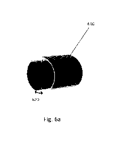
The conductive wire may be provided with any number of turns in order to
provide its function. For example, the conductive wire form a single turn
around a
receiving portion to provide a cylindrical element, as seen in Figure 6a. In
this way,
the conductive wire 610 may be formed of a single sheet that is configured to
wrap
around the receiving portion, such as receiving portion 104 described above.
As can
be seen in Figure 6b, the conductive wire 610 may therefore be provided with a
simple
shape such as a rectangle or a square with a given thickness that may be bent,
wrapped or otherwise provided around the receiving portion. The conductive
wire 610
may be provided with dimensions x and y such that it may be wrapped around a
desired
amount of the receiving portion, without forming a complete cylinder such that
there is
provided a gap 620 between opposing ends of the conductive wire 610. Such a
gap
620 avoids an electrical connection/short occurring between the opposing ends
of the
conducting wire 610.
Such a single turn conductive wire 610 may alternatively define the receiving
portion itself, without the need for a separate receiving portion positioned
between the
conductive wire and the space in which a consumable is to be received. Again,
such
an embodiment may improve the transfer of heat energy from the conductive wire
110
to aerosolisable material in a received consumable article. Advantageously, by
omitting a separate receiving portion, it is possible to reduce the overall
thermal mass
of the apparatus, which results in faster heating of a consumable article
comprising the
aerosolisable material that is to be heated.
CA 03172459 2022- 9- 20
WO 2021/260200
PCT/EP2021/067561
- 16 -
In such a case, a single turn conductive wire may be provided with an external
support structure 730 as seen in Figure 7. In this way the outward facing
surfaces of
the conductive wire 610 may be supported and/or mounted on an internal surface
of
the support structure 7300, such that the conductive wire 610 and the support
structure
730 form a heating chamber without the need for a separate, thermally
conductive,
internal support. One such way of retaining the conductive wire 610 in
position within
the opening 740 in the support structure 730 is to rely on the natural
resilience of the
conductive wire 610 that biases the wire against the inside of the opening 740
of the
support structure 730. Additionally, in order to maintain the gap 620 provided
by the
single wrap conductive wire 610 when it is bent into position, the support
structure may
be provided with a protrusion 750, which provides a physical barrier between
the
opposing ends of the conductive wire 610. Advantageously, such a protrusion
may
also be utilised as a rest for locating a received consumable article. In this
way, the
consumable article that has been introduced in through the opening 740 into a
receiving portion defined by the conductive wire 610 may be retained so as to
not
directly contact the conductive wire 610.
In some embodiments, the support structure 730 may be made of a material
capable of withstanding temperatures necessary to volatise one or more
components
of the aerosolisable material. For example, the support structure may be made
of a
plastics material, and may comprise PEEK. Additionally or alternatively, the
support
structure may comprise ceramic materials.
Alternatively, the conductive wire may comprise more than one turn, such as
two turns, as seen in conductive wire 810 of Figure 8a, three turns, as seen
in
conductive wire 811 of Figure 8b, or more turns, as seen in Figures 1 to 5.
When
there is provided more than one turn, each turn of the coil is electrically
isolated from
adjacent turns. In such embodiments, each turn of the coil is separated from
adjacent turns by an air gap. In some embodiments, the coil may be
encapsulated in
a dielectric material.
Conductive wires, such as the ones discussed herein need not necessarily be
provided as a substantially cylindrical heater. As would be appreciated, such
CA 03172459 2022- 9- 20
WO 2021/260200
PCT/EP2021/067561
- 17 -
conductive wires may be able to be used as a flat, planar heater that is
configured to
heat up a desired planar area.
The conductive wire may be provided with dimensions so as to provide
desired heating characteristics, when an electrical current is passed
therethrough.
Essentially, the rate of heating of the conductive wire is governed by the
resistance of
the conductive wire, which may be calculated using the following formula:
1
R = p A
Equation 1
Where R is the resistance of the conductive wire, p is the resistivity of the
material of the conductive wire, I is the length of the wire and A is the
cross sectional
area of the wire. For a substantially rectangular cross section of conductive
wire, the
cross sectional area is given by the thickness of the wire, multiplied by the
width of the
wire.
Using Equation 1, for a known material with a known resistivity, it is
possible to
modify the shape and thickness of the conductive wire so as to give a desired
resistance, as well as coverage of the conductive wire on an associated area
to be
heated. For example, it may be desired that the resistance of the conductive
wire is
around 0.3Q to provide a desired rate of heating, whilst being operable by a
power
source of the device. From this, it becomes possible to design the arrangement
of a
conductive wire.
As would be appreciated, by providing a thinner conductive wire, it is
possible
to produce a conductive wire with a lower thermal mass, such that the
conductive wire
heats up faster and provides the quickest subsequent heating of a consumable
article
positioned therein. However, a thicker conductive wire may be easier to
manufacture,
and more robust.
Based on these parameters, the conductive wires may be designed so as to
provide their desired characteristics. For example, a single turn conductive
wire 610
may be provided with desired width and length, a and b, as seen in Figure 6b,
and a
CA 03172459 2022- 9- 20
WO 2021/260200
PCT/EP2021/067561
- 18 -
desired thickness to provide a given resistance, whilst covering a desired
area. The
conductive wire of a two turn or three turn configuration may be designed so
as to
cover a desired area, with using a conductive wire 810, 811 with width of c,
or d and a
corresponding thickness.
One such way of providing a desired resistivity from a thicker material may be
to utilise one or more trace 910, such as one that is seen in Figure 9. Such
an trace(s)
may be designed to provide a suitable heating area (or several heating areas)
i.e. area
of trace, by rearranging Equation 1. For example, it may be desired to heat an
area of
around 100mm2, for which different dimensions e, f and g may be calculated.
Such a
conductive wire may be used in a planar heater, or wrapped around a consumable
as
above.
As above, the conductive wire 110, 610, 810, 811, 911 may formed of a metal
material; for example, the conductive wire may include one or more of:
aluminium,
copper, nnanganin, steel, constantan, nichronne, stainless steel, nickel and
fecralloy
(RTM). In other embodiments, the conductive wire 110, 610, 810, 811, 911 may
be
formed of a ceramics material. However, it has been found that it may be
beneficial to
provide a material with a relatively high resistivity for the conductive
wires. This allows
for reduced geometries of conductive wires to provide a desired resistance,
and
therefore allows for a shorter, thinner heaters, compared to wires of
materials with a
lower resistivity. For example, a desired minimum resistivity may be 0.9
ohm.mm2/m.
This is particularly beneficial in the field of tobacco heating products, as
it allows for
the use of smaller consumable articles. Equally, it may be desired that the
resistivity
is not too high, as it becomes harder to effectively power using a power
source.
Therefore, a desired maximum resistivity may be 1.6 or 1.5 ohm.mm2/m. A non-
exhaustive list materials that fall within this desired range are presented
below, in Table
1.
Material Resistivity
ohnn/rn ohm.mm2/m
Fecralloy (RTM) 1.34E-06 1.34
Nichrome 1.10E-06 1.10
Alkrothal (RTM) 1.20E-06 1.20
CA 03172459 2022- 9- 20
WO 2021/260200
PCT/EP2021/067561
- 19 -
Kanthal (RTM) 1.45E-06 1.45
Nikrothal (RIM) 1.09E-06 1.09
Table 1
It is also desirable that the thermal coefficient of resistance is as low as
possible, meaning that the resistivity of the material does not change
depending on
temperature. For example, fecralloy may be particularly desirable as its
thermal
coefficient of resistance is in the order of 0.0001 0/K.
As would be appreciated, all of the conductive wires above may also be found
in an arrangement similar to that of Figure 5, with multiple heating zones
provided by
multiple coils. Taking the example of Figure 5, the first coil 502 and/or the
second
coil 504 may be provided by a single turn arrangement such as conductive wire
610
of Figure 6, connected in the same manner as discussed above with regards to
Figure 5. Equally, the first coil 502 and the second coil 504 may be provided
by
conductive wires with different lengths, numbers of turns, widths and
thicknesses,
depending on the desired heating profile of their respective heating zones.
When there is provided multiple heating zones, it may be beneficial to provide
a receiving portion 1004, 1005 with several different corresponding thermally
independent zones HZ1 and HZ2, to prevent heat bleed between the individual
zones. For example, a first coil 502 may be provided around HZ1, and a second
coil
504 may be provided around HZ2. Length x of HZ1 and length v of HZ2 may be
varied such that they correspond to the respective lengths of first coil 502,
and
second coil 504.
As seen in Figure 10, HZ1 and HZ2 of receiving portion 1004 may be spaced
apart by a heat stop 1006. The heat stop 1006 may be made from a material with
a
significantly lower thermal conductivity, such that heat may not bleed between
HZ1
and HZ2, keeping these zones thermally independent. This allows for the
effective
creation of two separate heating zones that heat two sections of a consumable
article
that is provided inside the receiving portion independently. HZ1 and HZ2 may
be
made out of either the same, or different materials. For example, HZ1 and HZ2
may
be made from anodised aluminium, or high carbon steel, whereas the heat stop
1006
may be made from PEEK. The heat stop 1006 should be as thin as possible,
whilst
CA 03172459 2022- 9- 20
WO 2021/260200
PCT/EP2021/067561
- 20 -
still providing relative thermal independence of HZ1 and HZ2. For example,
heat
stop 1006 may have a width w of 1mm, which combined with the width u of HZ1,
and
width v of H72, provide a total length z of the receiving portion 1004. HZ1,
HZ2 and
heat stop 1006 may be provided together by any suitable connection. For
example,
the heat stop 1006 may be held in place by retaining the positions of HZ1 and
HZ2
such that they hold the heat stop 1006 between them in compression.
Additionally,
or alternatively, there may be a mechanical connection between HZ1, HZ2, and
heat
stop 1006. Such an arrangement allows for the use of a high thermal
conductivity
material throughout the receiving portion 1004, and physically stops heat
bleed such
that fully independent heating zones can be created.
Alternatively, as seen in Figure 11, HZ1 and HZ2 of receiving portion 1104
may not be spaced apart, and rather they may be provided together. In this
embodiment, HZ1 may be provided with a material with a relatively high level
of
thermal conductance, and HZ2 may be provided with a material of a relatively
lower
level of thermal conductance. For example, HZ1 may be made of anodized
aluminium, whereas HZ2 may be made from a mild steel or a high carbon steel.
HZ1
may be provided with width x, and HZ2 may be provided with width y so as to
provide
a total length z in which a consumable article may be received. In such a
case, HZ1
may be designed so as to allowed the fastest time to first puff of a received
consumable article with minimal energy usage, whereas HZ2 may be designed to
facilitate an independent zone that takes longer to come up to temperature to
promote longevity. As would be accepted, as there is no heat stop between HZ1
and
HZ2 in receiving portion 1014, there would be a limited amount of heat bleed
between these potions, although this would be mitigated by the relative
differences in
thermal conductivity between HZ1 and HZ2. Again, HZ1 and HZ2 may be connected
by any suitable method. For example, HZ1 and HZ2 may simply be held in
compression, or alternatively the may be provided with an overlap and then
welded,
for example, they may be laser welded together. Such an arrangement allows for
the
entirety of the receiving portion to be used for heating the consumable
article that is
provided therein.
As shown in Figure 12, a consumable, shown generally as 1200, may be
provided for use in a tobacco heating device (not shown). The consumable 1200
CA 03172459 2022- 9- 20
WO 2021/260200
PCT/EP2021/067561
- 21 -
may include a trace applied to a backing sheet 1203. The trace, for example,
includes material that conducts electrical current when applied to the tobacco
heating
device (not shown). The trace may include a current inlet 1201, a central
portion
1204 and a current outlet 1202. It is envisaged that when the consumable 1200
is
applied to a tobacco heating device, the current inlet 1201 and current outlet
1202
would connect with the tobacco heating device such that electrical current may
flow
through the trace for heating the consumable 1200. The central portion 1204 of
the
trace may include a planar aerosolisable material 1205 that would be consumed
by
the user, in use. For example, the aerosolisable material 1205 may be in the
form of
an aerosolisable gel or compact powder provided on the central portion 1204 of
the
trace.
In the example shown in Figure 12, the central portion 1204 of the trace and
the aerosolisable material 1205 are a disc shape. However, it is envisaged
that any
shape, e.g. rectangle, square, triangle, etc. may be used for the consumable
1200.
The backing sheet 1203 on which the trace and aerosolisable material 1205 are
provided is, as an example, cardboard or paper. Of course, any other material
that
does not conduct electrical current may be used for the backing sheet 1203.
In the example shown in Figure 12, there is shown one conductive trace on
the consumable. However, it is envisaged that there may be more than one trace
that are independently operable and configured to heat portions of the
aerosolisable
material. In an example, there may be two or more central portions that heat
two or
more portions of the aerosolisable material. Additionally or alternatively,
where there
are more than one traces, then each trace may be configured to heat separate,
respective portions of aerosolisable material. For example, there may be three
disc
shaped traces, that heat three corresponding disc shaped portions of
aerosolisable
material.
The trace (or traces) including the current inlet 1201, the current outlet
1202
and the central portion 1204 may be formed from a metallic material such as
aluminium, copper, manganin, steel, constantan, nichrome, stainless steel,
nickel
and fecralloy (RTM). Preferably, a desired minimum resistivity may be 0.9
ohm.mm2/m. A desired maximum resistivity may be 1.6 or 1.5 ohm.mm2/m. A non-
CA 03172459 2022- 9- 20
WO 2021/260200
PCT/EP2021/067561
- 22 -
exhaustive list materials that fall within this desired range are presented
above, in
Table 1.
In Figure 13, an alternative to the consumable 1200 is shown. As shown in
Figure 13, there is provided a trace that includes a current inlet 1301, a
current outlet
1302 and a receiving portion 1304 in the tobacco heating device (not shown). A
removable consumable 1300 may include a backing sheet 1303 and a planar
aerosolisable material 1305 attached to the backing sheet 1303. The receiving
portion 1304 of the trace in the tobacco heating device is configured to
receive the
removable consumable 1300 ¨ i.e., the backing sheet 1303 and planar
aerosolisable
material 1305 are able to be received by the receiving portion 1304 of the
trace within
the tobacco heating device. Once the removable consumable 1300 is inserted
into
the tobacco heating device, electric current may flow through the current
inlet 1301 to
the receiving portion 1304 in order to heat the aerosolisable material 1305
for
consumption.
As shown in Figure 13, the receiving portion 1304 of the trace and the
aerosolisable material 1305 may be a disc shape. However, it is envisaged that
any
shape, e.g. rectangle, square, triangle, etc. may be used for the consumable
1300 or
the receiving portion 1304 of the trace. The backing sheet 1303 on which the
aerosolisable material 1305 is provided is, as an example, cardboard or paper.
Of
course, any other material that does not conduct electrical current may be
used for
the backing sheet 1303.
In the example shown in Figure 13, there is shown one conductive trace for a
tobacco heating device. However, it is envisaged that there may be more than
one
trace that are independently operable and configured to heat portions of the
aerosolisable material. In an example, there may be two or more receiving
portions
that heat two or more portions of the aerosolisable material.
The trace (or traces) including the current inlet 1301, the current outlet
1302
and the receiving portion 1304 may be formed from a metallic material such as
aluminium, copper, manganin, steel, constantan, nichrome, stainless steel,
nickel
and fecralloy (RTM). Preferably, a desired minimum resistivity may be 0.9
CA 03172459 2022- 9- 20
WO 2021/260200
PCT/EP2021/067561
- 23 -
ohm.mm2/m. A desired maximum resistivity may be 1.6 or 1.5 ohm.mm2/m. A non-
exhaustive list materials that fall within this desired range are presented
above, in
Table 1.
The various embodiments described herein are presented only to assist in
understanding and teaching the claimed features. These embodiments are
provided
as a representative sample of embodiments only, and are not exhaustive and/or
exclusive. It is to be understood that advantages, embodiments, examples,
functions, features, structures, and/or other aspects described herein are not
to be
considered limitations on the scope of the invention as defined by the claims
or
limitations on equivalents to the claims, and that other embodiments may be
utilised
and modifications may be made without departing from the scope of the claimed
invention. Various embodiments of the invention may suitably comprise, consist
of,
or consist essentially of, appropriate combinations of the disclosed elements,
components, features, parts, steps, means, etc., other than those specifically
described herein. In addition, this disclosure may include other inventions
not
presently claimed, but which may be claimed in future.
CA 03172459 2022- 9- 20