Note : Les descriptions sont présentées dans la langue officielle dans laquelle elles ont été soumises.
CA 03189735 2023-01-18
# 1 -
Sealing profile and method for producing a plurality of sealing profiles
The invention relates to a method for producing a plurality of strip-shaped
sealing profiles
for an edge joint, which edge joint is formed between a floor and adjacent
cladding of
drywall. The invention also relates to a sealing profile which is produced
using such a
method.
Edge joints, in particular floor joints, are designed to provide sound
decoupling of the
drywall from adjacent walls, ceilings, or floors, in particular floorings.
The wall surfaces of the drywalls are formed by cladding parts such as gypsum
boards,
which often have to be protected from moisture. The edge joints therefore also
form a
barrier that protects the cladding parts against rising moisture, for example
in the event
of a pipe burst.
The edge joints are often sealed with sealing profiles that can be assembled
with little
effort, provide a sound and fire protection function, and reliably seal the
joint against air
and odors. Such sealing profiles often have a complex structure with sealing
portions
and fastening portions made of different materials.
The production process of such sealing profiles is complex and usually
comprises a
plurality of method steps in which parts of the sealing profile are extruded
and then
connected to one another.
The object of the invention is to provide a method by means of which a
plurality of sealing
profiles with a complex structure can be produced with particularly little
effort. It is also
an object of the invention to provide a sealing profile which is produced
particularly
efficiently in this way.
CA 03189735 2023-01-18
7 2 - ,
To achieve the object, a method for producing a plurality of sealing profiles
for an edge
joint is provided, which edge joint is formed between a floor and adjacent
cladding of
drywall. The method comprises the following steps:
a) providing a first web of sealing material,
b) applying a plurality of adhesive strips to the first web, wherein the
adhesive strips
each extend in a first direction of the web and adjacent adhesive strips of
two
adjacent sealing profiles are at a distance from one another in a second
direction
perpendicular to the first direction, which distance corresponds to at least
50% of
the height of a sealing profile,
c) providing a second web,
d) merging and joining the first web with the second web via the adhesive
strips to
form a multilayer web, and
e) introducing a plurality of vertical cuts in the first direction in the
multilayer web at
a distance from all adhesive strips to form a number of sealing profiles,
wherein
each cut separates two sealing profiles from one another, wherein each cut is
at
the smallest distance from the adhesive strip of one of its assigned sealing
profiles, which distance corresponds to at most 20% of the height of the
sealing
profile, and is at the smallest distance from the adjacent adhesive strip of
the
other of its assigned sealing profiles, which distance corresponds to at least
50%
of the height of the sealing profile perpendicular to the first direction. The
sealing
profiles each form a sealing profile or a sealing profile blank, i.e. an
intermediate
product of a sealing profile.
According to the invention, it was recognized that in this way a plurality of
sealing profiles
can be produced with little effort, which have a complex structure.
The sealing profiles each have a base body for sealing the edge joint and a
fastening
portion which is attached to the base body via at least one adhesive strip.
CA 03189735 2023-01-18
,
Due to the way in which the adhesive strips and cuts are applied or introduced
during
the production method, the base bodies are only connected to the fastening
portion on
one side, for example at the bottom, while an upper portion of the base body
is not
fastened laterally to the fastening portion. As a result, the upper portion
can be resiliently
deformed or compressed particularly strongly in the vertical direction. In
this way, in the
installed state, the sealing profile adapts to the joint width of the edge
joint over a
particularly large vertical region and thus seals it off effectively. The
fastening portion
also ensures a defined and reliable fastening of the sealing profile to a
holding rail of the
drywall, so that assembly can be carried out with little effort.
In one embodiment, the following step is carried out before step e):
f) applying a plurality of assembly aid strips to the second web, wherein the
assembly aid strips are arranged opposite to the first web and each extend in
the
first direction of the second web, wherein each adhesive strip is assigned an
assembly aid strip.
By means of the assembly aid strips, the sealing profiles can be reliably
assembled with
little effort, in particular on a holding rail of the drywall. The application
of a plurality of
assembly aid strips has the advantage that the width of the assembly aid strip
can be
smaller than the width of the sealing profile or the height of the sealing
profile.
Alternatively, the following step can be carried out before step e):
g) applying an assembly aid layer to the second web, wherein the assembly aid
layer is arranged opposite to the first web and, after introducing a plurality
of
vertical cuts in step e), forms a plurality of assembly aid strips, each of
which
extend in the first direction of the second web and are assigned to one of the
sealing profiles.
This step has the advantage that the assembly aid strips of the sealing
profiles are
applied in a coherent layer and are only divided up afterwards.
Furthermore, the following step can be carried out after step d):
CA 03189735 2023-01-18
,
h) introducing a plurality of vertical cuts in the first direction in the
first web to form
sealing profiles with a stepped profile.
In this way, sealing profiles with portions of different heights can be
produced with little
effort in order to provide correspondingly differentiated sealing functions.
In a further embodiment, in step h) the plurality of vertical cuts extends
completely in the
vertical direction through the first web, but not in or through the second
web. Thus, the
portion of the sealing profile that is formed by the first web has a different
height than the
portion of the sealing profile that is formed by the second web.
It can be provided that step h) is carried out before or together with step
e), i.e. at a point
in time at which the sealing profiles are still connected to one another and
thus cuts can
be made in a defined manner with little effort.
It is advantageous if the first web and/or the second web is roll goods, since
roll goods
can be produced particularly inexpensively and in great lengths.
According to one embodiment, the sealing material of the first web is a foam,
in particular
.. an open-cell or at least partially open-cell foam, which is particularly
flexible.
According to a further embodiment, the second web is formed from a plastics
material or
a foam, in particular from a closed-cell foam, in order to provide high
strength and/or
resistance.
Furthermore, it can be provided that each sealing profile has exactly one
adhesive strip.
As a result, the connection between the portion of the first web and the
portion of the
second web can be designed particularly narrow.
In one embodiment, the webs used are plate-shaped with a constant thickness in
order
to ensure sealing profiles with defined and constant dimensions.
In a further embodiment, the first web has a thickness that is at least 3
times greater than
that of the second web. Thus, the portion made of the sealing material is
designed
CA 03189735 2023-01-18
-f 1111 7 5
particularly wide compared to the portion made of the second web and ensures
an
effective sealing of the edge joint.
According to the invention, a sealing profile is also provided to achieve the
above-
mentioned object, which was produced by the method according to the invention
with the
advantages mentioned above.
Further advantages and features emerge from the following description and from
the
accompanying drawings. In the drawings:
Fig. 1 is a schematic sectional view of a sealing profile according to the
invention,
Fig. 2 is a schematic sectional view of a sealing profile according to the
invention in
accordance with a further embodiment,
Fig. 3 is a schematic view of a production line in which sealing profiles
according to the
invention are produced in accordance with a method according to the invention,
and
Fig. 4 to 8 are in each case a schematic sectional view of individual steps of
the method
from Fig. 3.
Fig. 1 is a cross section of drywall 10 with cladding 12 (gypsum wall) and a
holding rail 14,
which is part of a stand construction of the drywall 10. An edge joint 16 in
the form of a
floor joint, which is sealed by a sealing profile 20, is formed between a
circumferential
side 18 of the cladding 12 and the floor 8. Fig. 1 shows the drywall 10 in a
not completely
assembled state, in which the cladding 12 has not yet been installed and is
therefore not
yet bearing against the sealing profile 20. The cladding 12 is therefore only
shown in
dashed lines to illustrate its position.
The sealing profile 20 has a base body 22, which forms a sealing portion
between the
circumferential side 18 of the cladding 12 and the floor 8, and a fastening
portion 24,
which is arranged between the base body 22 and the holding rail 14.
The base body 22 has a rectangular cross section with an underside 26 facing
the floor
8, an upper side 28 facing the cladding 12, against which upper side the
cladding 12
CA 03189735 2023-01-18
,
rests with the circumferential side 18 in the assembled state, an inner side
30 opposite
to the fastening portion 24, and an outer side 32 opposite to the inner side
30.
The fastening portion 24 has a rectangular cross section and extends in the
vertical
direction V up to an end 34 facing away from the floor 8, which in the
unassembled state
ends at the same vertical height as the upper side 28 of the base body 22.
In the embodiment shown in Fig. 1, both the base body 22 and the fastening
portion 24
thus have the same vertical height B.
In the horizontal direction H, the base body 22 has a thickness D which is
approximately
400% of the thickness d of the fastening portion 24.
Of course, the base body 22 can have a thickness D of any size. The thickness
D of the
base body 22 is preferably at least 300% of the thickness d of the fastening
portion 24.
In principle, it is an advantage if the base body 22 has a thickness D which
corresponds
to the corresponding thickness of the cladding 12 so as to seal the sealing
edge joint 16
over the entire depth.
The base body 22 consists of a sealing material made of open-cell foam, for
example a
foam based on PE, XPE, or EPDM.
In an alternative embodiment, the base body 22 consists at least partially of
open-cell
foam.
The fastening portion 24 consists of a closed-cell foam.
In an alternative embodiment, the fastening portion 24 can be formed of a
plastics
material, for example EPDM, PVC, foam rubber, thermoplastic elastomer, or
silicone.
The sealing material of the base body 22 and the material of the fastening
portion 24 are
in each case roll goods.
CA 03189735 2023-01-18
7 7 -
In principle, the base body 22 and the fastening portion 24 can each be formed
from any
desired material or sealing material.
The base body 22 is connected to the fastening portion 24 via an adhesive
strip 36 of
the sealing profile 20, which extends from a lower end 38 at the bottom to an
opposite
upper end 40.
Of course, the adhesive strip 36 may not be continuous but may rather be
interrupted in
the vertical direction V and/or in the direction of extent of the profile. In
other words, the
adhesive strip 36 can consist of a plurality of strip portions that are
adjacent in the vertical
direction V and/or in the direction of extent of the profile.
Preferably, however, the adhesive strip 36 is a single strip, in particular
with a constant
width in the vertical direction V.
The adhesive strip 36 is arranged at the bottom.
Specifically, this means that the lower end 38 of the adhesive strip 36 is at
a distance a
in the vertical direction V from the underside 26 of the base body 22, which
distance
corresponds to approximately 5% of the height B of the base body 22.
Furthermore, the upper end 40 of the adhesive strip 36 is at a distance A in
the vertical
direction V to the end 34 of the fastening portion 24, which distance
corresponds to
approximately 75% of the height B of the base body 22.
In an alternative embodiment, the distance a is a maximum of 20%, in
particular a
maximum of 10% of the height B.
Additionally or alternatively, the distance A can be at least 50%, in
particular at least 60%
of the height B in an alternative embodiment.
The base body 22 is connected to the fastening portion 24 exclusively via the
adhesive
strip 36.
CA 03189735 2023-01-18
r 8 -
In the embodiment shown, the inner side 30 is separated from the fastening
portion 24
by a vertical gap 42.
In an alternative embodiment, the base body 22 can rest against the fastening
portion 24
.. via its inner side 30, but in all embodiments the inner side 30 is only
firmly connected to
the fastening portion 24 via the adhesive strip 36.
To fasten the sealing profile 20 to the holding rail 14, the sealing profile
20 has an
assembly aid strip 44 which is attached to the fastening portion 24 on the
side opposite
.. the base body 22.
The assembly aid strip 44 is, for example, a double-sided adhesive tape with
masking
paper, which protects the adhesive tape until assembly and is peeled off
before
assembly.
In the assembled state, the base body 22 is arranged compressed in the
vertical direction
V in the edge joint 16. In this case, the fastening portion 24 forms a sealing
web which
seals an intermediate space between the holding rail 14 and the cladding 12.
Because the base body 22 is only fastened to the fastening portion 24 at the
bottom, the
upper base body 22 can be resiliently deformed particularly well in the
vertical direction
V, as a result of which its vertical height can vary over a particularly large
range,
depending on the load.
.. In this way, the sealing profile 20 reliably seals the edge joint 16 as
long as the joint width
is provided within the comparatively wide range for which the sealing profile
20 is
intended.
The region for which the sealing profile 20 is provided is in particular 1/4"
(0.635 cm) to
3/4" (1.905 cm). This means that the base body 22 is configured to reliably
seal joint widths
of 1/4" (0.635 cm) to 1/4" (1.905 cm) and for this purpose has a vertical
height B of at least
2 cm, for example.
A sealing profile 20 according to a further embodiment will now be described
with
.. reference to Fig. 2. The same reference signs are used for the components
which are
CA 03189735 2023-01-18
9 -
known from the above embodiment and in this respect reference is made to the
preceding explanations.
In contrast to the embodiment shown in Fig. 1, the fastening portion 24
extends in the
unloaded state of the sealing profile 20 in the vertical direction V by the
height b beyond
the upper side 28 of the base body 22. In other words, the end 34 terminates
at a vertical
height that is above the upper side 28. This also means that the vertical
height of the
base body 22 is smaller by the height b than the height B of the fastening
portion 24. As
a result, the sealing profile 20 has a step-shaped cross section or a stepped
profile, in
which the base body 22 and the fastening portion 24 each form a step with a
different
vertical height.
To produce the aforementioned sealing profiles 20, a method is provided which
is
explained below with reference to Fig. 3 to 8. The production of the
embodiment shown
in Fig. 1 takes place according to the steps shown in Fig. 4 to 7, while the
embodiment
shown in Fig. 2 takes place according to the steps shown in Fig. 4 to 6 and 8.
In the method, a plurality of sealing profiles 20 is produced in parallel.
Fig. 4 to 8 show
the production of ten sealing profiles 20, the strip-shaped sealing profiles
20 or sealing
profile blanks being machined simultaneously in each step.
In principle, any number of sealing profiles 20 can be produced in parallel
with the
method, but preferably at least 5.
Fig. 3 shows a production line 50 with a first roll 52, an adhesive device 54,
a second
roll 56, an application device 58, and a cutting device 60, which are arranged
one behind
the other in the longitudinal direction Z according to the production steps.
In this case, the first roll 52 provides a first web 62 which forms the base
bodies 22 of
the sealing profiles 20 and is accordingly formed from the same sealing
material as this.
Furthermore, the first web 62 has a thickness in the Y direction that
corresponds to the
thickness D of the base body 22.
CA 03189735 2023-01-18
", 1
The second roll 56 provides a second web 64 which forms the fastening portions
24 of
the sealing profiles 20 and is accordingly formed from the same material as
this.
Furthermore, the second web 64 has a thickness in the Y direction that
corresponds to
the thickness d of the fastening portion 24.
The first web 62 and the second web 64 are therefore each roll goods.
In a first step, the first web 62 is provided.
In a subsequent step, the adhesive device 54 is used to apply a number of
adhesive
strips 36 (see Fig. 4) to the first web 62, which corresponds to the number of
sealing
profiles 20 to be produced.
The adhesive strips 36 are in this case applied parallel to one another, in
the longitudinal
direction Z and in each case on a sealing profile 20 assigned thereto.
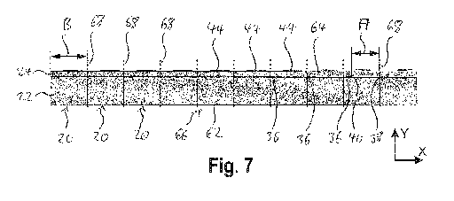
The distance E in the X direction between two adjacent adhesive strips 36,
i.e. between
the upper end 40 of one adhesive strip 36 and the opposite lower end 38 of the
adjacent
.. adhesive strip 36, corresponds to 80% of the height B of a sealing profile
20 (see Fig. 7).
In an alternative embodiment, the distance E can correspond to at least 50% of
the
height B of a sealing profile 20.
In a further step, the provided second web 64 is brought together with the
first web 62
and bonded to form a multilayer web 66 (see Fig. 5) by means of the adhesive
strips 36.
They are brought together and connected, for example, by means of a device
with rollers.
Subsequently, by means of the application device 58, a number of assembly aid
strips 44
(see Fig. 6) opposite to the first web 62 are applied to the second web 62,
which
corresponds to the number of sealing profiles 20 to be produced.
The assembly aid strips 44 are applied parallel to one another, in the
longitudinal
direction Z and on a sealing profile 20 assigned to them.
CA 03189735 2023-01-18
1 1
In an alternative embodiment, instead of the individual assembly aid strips
44, a coherent
assembly aid layer is applied, which is severed into corresponding assembly
aid strips 44
in a subsequent step, in particular by means of the first cuts 68 described
below.
In a subsequent step, a plurality of first cuts 68 (see Fig. 7) are made in
the longitudinal
direction Z by means of the cutting device 60 and each cut through the
multilayer web 66
in the Y direction.
The first cuts 68 each separate two sealing profiles 20 from one another. This
means
that the number of first cuts 68 is one less than the number of sealing
profiles 20 that are
produced in parallel, i.e. nine in the present embodiment.
In an alternative embodiment, a further cut can be provided at one or both
outer ends in
the X direction of the multilayer web 66 in order to cut the ends to length in
a defined
manner. In particular in the case in which the first web 62 and/or the second
web 64 are
wider in the X direction than the total of the sealing profiles 20 produced in
parallel.
Adjacent first cuts 68 each have a distance B which corresponds to the height
B (see
Fig. 1) of the sealing profile 20, which is delimited by the two adjacent
first cuts 68.
Each first cut 68 is also arranged between the adhesive strips 36 of the two
adjacent
sealing profiles 20, i.e. at a distance from these.
In this case, each first cut 68 is at a distance A from the upper end 40 of
the one adhesive
strip 36, which distance corresponds to the distance A (see Fig. 1) of the
adhesive
strip 36 in the vertical direction V to the end 34 of the fastening portion 24
of the one
sealing profile 20, and which distance corresponds, in the present embodiment,
to
approximately 75% of the height B of the base body 22.
Furthermore, each first cut 68 is at a distance from the lower end 38 of the
other adhesive
strip 36, which distance corresponds to the distance a (see Fig. 1) of the
adhesive
strip 36 in the vertical direction V to the underside 26 of the base body 22
of the other
sealing profile 20 and which distance corresponds, in the present embodiment,
to
approximately 5% of the height B of the base body 22.
CA 03189735 2023-01-18
= 12 -
In an alternative embodiment, the first cut 68 can have the smallest distance
A from an
adjacent adhesive strip 36, which distance corresponds to at least 50% of the
height B
of the sealing profile 20.
Additionally or alternatively, the first cut 68 can have the smallest distance
to the other
adjacent adhesive strip 36, which distance corresponds to at most 20% of the
height of
the sealing profile 20.
In order to produce the step-shaped sealing profiles 20 shown in Fig. 2, in
addition to the
first cuts 68 by means of the cutting device 60, a plurality of second cuts 70
(see Fig. 8)
are introduced in the longitudinal direction Z, which cut through the first
web 62 in the Y
direction.
However, the second cuts 70 do not extend into the second web 64 and thus
leave it
untouched.
Every second cut 70 is arranged between the adhesive strip 36 of the assigned
sealing
profile 20 and the first cut 68 or the outer end of the multilayer web 66,
which cut or end
is provided at a distance A from the corresponding adhesive strip 36.
In this case, every second cut 70 is at a distance b from the assigned first
cut 68 or outer
end of the multilayer web 66, which distance corresponds to the height b (see
Fig. 2)
beyond which the fastening portion 24 extends in the unloaded state of the
sealing
profile 20 in the vertical direction V beyond the upper side 28 of the base
body 22.
The second cuts 70 are preferably made before or together with the first cuts
68.
The cutouts 72 formed by the first and second cuts 68, 70 can be removed in a
subsequent step.
In all embodiments, the sealing profiles 20 designed in this way can be cut
off in a specific
length in the longitudinal direction Z and wound up to form rolls 74 (see Fig.
3) in a space-
saving manner.
CA 03189735 2023-01-18
13 -
In an alternative embodiment, the multilayer web 66 can be rolled up into a
primary roll
before the first cuts 68 are introduced in a later step, for example by
cutting rolls 74 each
with a sealing profile 20 from the primary roll.
In a further alternative embodiment, the first and/or the second web 62, 64
can be
provided in the form of plates instead of roll goods, which are connected to
one another
in accordance with the aforementioned method and processed further to form a
plurality
of sealing profiles 20.
In this way, a method is provided by means of which sealing profiles 20 of
complex
design can be produced with little effort.
The invention is not limited to the embodiments shown. In particular,
individual features
of one embodiment can be combined in any way with features of other
embodiments, in
particular independently of the other features of the corresponding
embodiments.