Note : Les descriptions sont présentées dans la langue officielle dans laquelle elles ont été soumises.
1
METHOD FOR MANUFACTURING ANALYSIS CHIPS AND ANALYSIS CHIP THUS
OBTAINED
FIELD OF THE INVENTION
The present invention relates to the field of biological analyses, in
particular biochemical
analyses.
More specifically, the invention relates to a process for manufacturing filter
chips, which can
optionally be functionalized to carry out biological analyses.
TECHNOLOGICAL BACKGROUND
In the field of biological analyses, it is known to use protein chips
("protein microarrays") to
study the biochemical activity of proteins. In such chips, a library of
antibodies or protein
fragments ("probes") ¨ or even whole proteins ¨ is placed on a matrix such as
a glass slide. In
this case, a single sample is tested on all the probes deposited on the
matrix.
Biological analysis devices allowing the parallel analysis of several samples
have also been
developed.
Document W02014/053237 is an example in which a miniaturized device allows
analysis of
several biological samples simultaneously ("multiplex" analysis). Each sample
can also be
exposed to several different probes successively. In other words, the device
allows an analysis
of the "3D analysis" type.
The device described by this document comprises a plurality of channels, into
each of which a
sample in the liquid phase can be injected independently of the other
channels.
Each channel can be formed from several tubular portions. Between two
successive portions
an approximately cylindrical analysis zone formed in an appropriate matrix is
inserted.
The analysis zones can in particular be formed in a flat nitrocellulose
matrix, the entire
surface of which, except for the analysis zones, is rendered hydrophobic by an
impregnation
of wax.
The analysis zones can simply consist of untreated nitrocellulose, so that
they constitute zones
of filtration, or alternatively of nitrocellulose functionalized for example
by means of a probe
molecule.
The impregnation operation with wax makes it possible to delimit the analysis
zones, but also
to limit the lateral diffusion inside the matrix (that is to say outside a
given analysis zone
towards the other neighboring analysis zones) of the molecules of interest
(probe molecules or
molecules of a sample).
CA 03197100 2023- 5- 1
8395685
2
For this impregnation operation, a solid ink printing process is implemented,
so as to deposit a
layer of wax on the matrix in the areas that must be rendered hydrophobic. At
the end of the
printing, the matrix is heated to a temperature higher than the melting point
of the used wax,
then cooled, so that the wax diffuses laterally and in depth, in the thickness
of the matrix, so
as to limit its subsequent undesirable distribution to the analysis areas.
However, such a process does not make it possible to finely control the volume
of a given
analysis zone or the shape of the surface which delimits this volume, as shown
in the figures
presented in this document. In particular, the circumference of the upper
surface of a test site
varies from site to site and is generally not circular, so that in the
direction of flow the section
of the analysis area is not precisely the same as the interior section of the
channel in which the
analysis area is to be inserted.
Consequently, the precision of such a device is limited due to the
manufacturing process used
to form the analysis zones, and concomitantly, the limit of quantification
remains too high for
certain biological analyzes in which the concentrations involved (or their
variations) are
particularly weak.
Document US2004/0115707 discloses a biochemical analysis unit comprising a
base plate
having a plurality of holes filled with a porous and adsorbent material so as
to form a plurality
of analysis zones.
The filling of the holes can be obtained by laminating a sheet of adsorbent
material on the
previously drilled base plate.
During lamination, the sheet of analysis material is stressed anisotropically
due to the tensile
force exerted in the direction of lamination. The properties of the adsorbent
material after
insertion into the holes are therefore anisotropic. It is even possible that
the thickness of the
adsorbent material varies within the same hole.
Moreover, the lamination does not break the continuity of the sheet of
adsorbent material. The
adsorbent material therefore forms a continuous surface between two channels
under or on the
plate, as can be observed in FIG. 2b of document US2004/0115707. The molecules
of interest
(from the sample or probes) therefore risk diffusing from one channel 3 to
another due to this
continuity.
The precision and sensitivity of a quantitative analysis performed with such a
plate are
therefore limited.
In another embodiment described by US2004/0115707, the adsorbent material can
be
dissolved in a solvent. The solution obtained is then injected into the holes
and the solvent
evaporated. This liquid phase injection technique also does not allow precise
control of the
CA 03197100 2023- 5- 1
8395685
3
isotropy of the properties of the test zone, in particular because the air
flow allowing the
evaporation of the solvent is necessarily directional.
In addition, traces of solvent may remain in the adsorbent material, which may
interact with
the probe molecules or molecules to be analyzed. In addition, the use of
solvents, in particular
organic solvents in the case of nitrocellulose, makes the process polluting.
Finally, the bond between the adsorbent material, once solidified, and the
base plate is not
ensured with certainty. The quality of this bond depends in particular on the
chemical
compositions of the adsorbent material and of the base plate. The connection
between a given
analysis zone and the plate can therefore prove to be fragile. In the event of
forced circulation
of liquid, by means of a relative vacuum, these analysis zones could come off
and be carried
away by the circulating liquid. It is therefore not possible to carry out an
analysis with forced
circulation of liquid through the analysis zones obtained by this embodiment.
Other processes, using different chemicals or a heating step or an irradiation
step, for
example, are also described in document W001/19502A2, after a first lamination
step.
In addition to the previously exposed disadvantages of lamination, all these
embodiments
have the disadvantage of causing physico-chemical modifications of the
filtering membrane
which alter its properties essential for the analysis and therefore the
sensitivity and precision
of the analysis.
Insofar as the chemical composition and the physical structure of the membrane
on which the
analysis is implemented influence the performance of the analysis method, and
in particular
the quantification limit of this method, the invention therefore aims to
propose a method for
manufacturing a chip for analyzing a biological sample making it possible to
finely control
this chemical composition and this physical structure.
In particular, the invention aims to provide a method for manufacturing a low-
cost analysis
chip, not requiring a heat, chemical or irradiation treatment step for the
formation of the test
sites in the matrix ( except during a possible biochemical functionalization
of these sites after
or before the formation of the sites) and making it possible to carry out a
quantitative analysis
of high precision and sensitivity and/or an analysis of a biological sample or
a simple
filtration of a liquid biological sample.
SUMMARY OF THE INVENTION
Thus, the invention relates to a method for manufacturing a biological sample
analysis chip
comprising:
CA 03197100 2023- 5- 1
8395685
4
- providing a matrix formed in a solid support material, having a lower
surface and an upper
surface and in which at least one through hole extending between said lower
and upper
surfaces has been formed;
- at least one pad is provided, cut from a sheet of solid and porous
analysis material, the pad
having a lower surface and an upper surface,
- one proceeds to the insertion of at least one pad in at least one through
hole of the matrix by
translation of the at least one pad in the direction normal to the lower and
upper surfaces of
the matrix;
- a mechanical assembly is carried out at a temperature below the melting
temperatures of the
support and analysis materials, during which a pressing force in the direction
normal to the
lower and upper surfaces of the matrix is exerted on at least a portion of the
matrix which
adjoins the at least one pad inserted into the matrix and/or on at least one
of the lower and
upper surfaces of the at least one pad inserted into the matrix.
Thanks to these provisions, an analysis chip is obtained comprising at least
one pad of
analysis material inserted into a hole passing through a support material. The
assembly
between the pad and the support material is not obtained by a chemical
process, nor by
melting one of the materials so that the physical and chemical properties of
the support and
analysis materials before assembly are not or at least are very little altered
after assembly,
including near the interface between these two materials. Assembly is obtained
only
mechanically and by exerting a pressing force normal to the upper and lower
surfaces of the
matrix, so that the deformation of the materials is uniform in a plane normal
to the direction
of the pressing force.
The method therefore makes it possible, unlike methods implementing a
lamination step, not
to introduce anisotropy into the support material and/or the analysis material
in a direction
normal to the direction of the pressing force.
Such an anisotropy would, for example, lead in the case of immunological tests
using
fluorescent reagents to inhomogeneous fluorescence on the surface of an
analysis pad, which
would make the quantitative analysis of the fluorescence signal imprecise.
Thanks to all of these arrangements, the sensitivity and the reproducibility
of an analysis chip
obtained by the method according to the invention are therefore improved
compared to chips
obtained according to the methods of the prior art.
In addition, the means to be implemented are only mechanical, therefore not
very polluting in
that they do not include solvent and they are simple to implement.
CA 03197100 2023- 5- 1
8395685
5
According to various aspects, it is possible to provide one and/or the other
of the
characteristics below taken alone or in combination.
According to one embodiment, in the method of manufacturing a biological
sample analysis
chip, the pressing force is exerted on a portion of the matrix which adjoins
the at least one pad
inserted into the matrix.
Thanks to this arrangement, this portion of the matrix can be folded over
and/or below the pad
so that the pad can be at least partially crimped by the matrix. Thus, the
assembly of the pad
to the matrix in the analysis chip will present a good mechanical resistance
and will not be
affected by the flow of a liquid sample to be analyzed in the direction normal
to the upper and
lower surfaces of the matrix, or even by a relative vacuum applied on the side
of one of these
surfaces in order to accelerate the flow of the liquid sample.
According to one embodiment of the method for manufacturing a biological
sample analysis
chip, the pressing force is exerted on at least one of the lower and upper
surfaces of the at
least one pad inserted into the matrix.
Thanks to this arrangement, the pad at least partially crimps the matrix so
that the assembly of
the pad to the matrix will present a certain mechanical resistance and it will
not be affected by
the flow of a liquid sample to be analyzed in the direction normal to the
upper and lower
surfaces of the matrix, or even by a relative vacuum applied on the side of
one of these
surfaces in order to accelerate the flow of the liquid sample.
According to a particular embodiment, in the method of manufacturing a
biological sample
analysis chip, the support material is hydrophobic and the analysis material
is hydrophilic or
vice versa. In this way, it is for example possible to deposit on the pad a
sample to be tested in
aqueous phase without it diffusing towards the support material if the latter
is hydrophobic.
Conversely, if the support material is hydrophilic, the analysis material is
hydrophobic and it
is then possible to deposit a sample to be tested in the organic phase on the
pad without it
diffusing towards the support material.
According to a particular embodiment, in the method of manufacturing a
biological sample
analysis chip, for inserting the at least one pad into the at least one
through hole, the at least
one pad is translated into the at least one through hole by means of a punch,
the at least one
pad having been cut out from the sheet of analysis material before its
insertion by means of
this same punch and the at least one through hole having been formed
beforehand in the
matrix by means of this same punch.
Thanks to this arrangement, a single tool is necessary to prepare an analysis
chip, namely a
tool having one or more punches of sizes and shapes adapted to the shapes of
the desired
CA 03197100 2023- 5- 1
8395685
6
wells. Such a tool is simple to design and implement and possibly allows
automation of the
process, which makes it possible to obtain high and controlled precision
analysis chips in a
reproducible, rapid and low-cost manner.
According to a particular embodiment, in the method of manufacturing a
biological sample
analysis chip, after the mechanical assembly, the at least one pad is
functionalized.
One can for example consider a biochemical functionalization, by means of an
antibody or an
antigen which is adsorbed on the pad.
In this way, the biological sample analysis chip obtained by the method makes
it possible to
implement an analysis test implementing the reagent used for the
functionalization, for
example an immunological test. The analysis chip can therefore be adapted to
the analysis
needs thanks to this functionalization step. The analysis chips can for
example be produced in
series before the functionalization step and each functionalized at will at
the time of the
analysis.
According to a particular embodiment, in the method of manufacturing a
biological sample
analysis chip, the analysis material is functionalized before inserting the at
least one pad into
the matrix.
Thanks to this arrangement, the functionalization can be done on the whole of
a sheet of
analysis material before cutting the pad. This saves time when the analysis
chips are prepared
in series. The control of the functionalization, and in particular of a
quantity of analysis
reagent deposited on each pad, is also better, which ultimately allows better
precision and
better reproducibility of the tests carried out with a given series of
analysis chips.
According to a particular embodiment, in the method of manufacturing a
biological sample
analysis chip, the insertion of the at least one pad into the matrix is
repeated at least once,
using for each new insertion a functionalized analysis material different from
that used for the
previous insertion and a punch corresponding to at least one through hole of
the matrix
different from that used for the previous insertion.
Thanks to this arrangement, it is possible to form several differently
functionalized analysis
pads on the same analysis chip. It is then possible to carry out several
different tests
simultaneously on the same chip, on the same sample or on several different
samples. The
process remains simple to implement since it only requires different punches
or equivalently a
single tool provided with several punches positioned at different places and
which can be
activated separately or in groups. According to a particular embodiment, in
the method of
manufacturing a biological sample analysis chip, the mechanical assembly of at
least one pad
CA 03197100 2023- 5- 1
8395685
7
with the matrix results in crimping of at least one pad on at least a portion
of its lower and
upper surfaces by the matrix.
Thanks to this arrangement, the pad cannot be pushed, under normal conditions
of use,
outside the matrix at least on one side of this matrix. The assembly of the
matrix and the pad
therefore resists a relative vacuum or the pressure exerted on one side of the
pad by the
sample to be tested when it is deposited.
According to a particular embodiment, in the method of manufacturing a
biological sample
analysis chip, before the insertion of the at least one pad into the matrix,
the at least one pad is
brought to a temperature lower than that of the matrix. Thanks to this
arrangement, the
analysis material shrinks before its insertion, which facilitates its
insertion into the through
hole by reducing the contact forces and it expands after insertion, so that
after insertion, the
contact between the pad and the matrix is secured and allows the pad to be
held in place in the
matrix.
The invention also relates to a biological sample analysis chip comprising:
- a matrix formed in a solid support material, having a lower surface and
an upper surface and
in which at least one through hole extending between said lower and upper
surfaces has been
formed;
- at least one pad, cut from a sheet of solid and porous analysis material
and inserted into the
at least one through hole, the at least one pad having a lower surface and an
upper surface, the
biological sample analysis chip being characterized in that the at least one
pad is crimped on
at least one of its upper and lower surfaces by the matrix.
Such an analysis chip has the advantage of not containing any residue of
solvent or melting or
soldering zone which could alter the precision of a test carried out with this
chip. Crimping
makes it possible both to preserve the native physico-chemical properties of
the support
material and of the analysis material. It also makes it possible to carry out
a test with flow of a
sample along the axis of the through hole from one side of the pad to the
other, since the
assembly between the pad and the matrix has good mechanical resistance.
According to one embodiment of the biological sample analysis chip sample, the
support
material comprises at least one component chosen from a metal, a plastic
material and
cellulose and in that the analysis material of which the at least one pad is
formed includes at
least one component selected from nitrocellulose, cellulose, and an organic
polymer.
Such materials are inexpensive and have the necessary qualities of biochemical
inertness and
adsorption to implement analyzes such as biochemical tests.
CA 03197100 2023- 5- 1
8395685
8
According to one embodiment of the biological sample analysis chip, the
assembly of the at
least one pad and of the matrix withstands at least a relative vacuum equal to
0.100 bar.
Thanks to this arrangement, it is possible to implement an analysis on a
sample flowing in a
forced manner through the pad without the pad separating from the matrix due
to the
overpressures which are exerted locally.
The invention also relates to a device for analyzing a biological sample
comprising at least
two superposed biological sample analysis chips according to one of the
preceding
embodiments and in which the at least one pad of one of the at least two chips
is configured to
perform a filtration function and is superimposed with the at least one
functionalized pad of
another chip of the at least two chips.
It is thus possible to stack several analysis chips to obtain a three-
dimensional analysis device,
the analysis carried out varying from one analysis site to another in the
direction of the
stacking and/or within a given analysis chip and to carry out a first
filtration step before the
analysis, in particular to separate the serum from the red blood cells with a
view to analyzing
a blood sample.
In the latter case, the device makes it possible to avoid a centrifugation
step.
The invention further relates to a diagnostic kit comprising at least one
biological sample
analysis according to one of the preceding embodiments and at least one
analysis reagent.
One or more analysis reagents, in particular a buffer, a solvent, an antigen,
an antibody, can
thus be provided in order to carry out a standardized test, such as an
immunological test.
The invention also relates to the use of a biological sample analysis chip
according to one of
the preceding embodiments for diagnostic purposes or for an immunological
test.
The invention finally relates to a device for manufacturing a biological
sample analysis chip
according to one of the preceding embodiments, the manufacturing device
comprising:
- an insertion system suitable for inserting the at least one pad into the
at least one through
hole of the matrix by translation of the pad in the direction normal to the
lower and upper
surfaces of the matrix;
- a mechanical assembly system at a temperature below the melting
temperatures of the
support and analysis materials, adapted to exert a pressing force in the
direction normal to the
lower and upper surfaces of the matrix on at least a portion of the matrix
which adjoins the at
least one pad inserted into the matrix and/or onto at least one of the lower
and upper surfaces
of the at least one pad inserted into the matrix.
Such a manufacturing device is simple to implement and introduces only minimal
and
isotropic deformation of the support and/or analysis material in any plane
parallel to the lower
CA 03197100 2023- 5- 1
8395685
9
and upper surfaces of the matrix. It therefore makes it possible to form
analysis chips at low
cost and while preserving the native physico-chemical properties of the
support and analysis
materials.
BRIEF DESCRIPTION OF DRAWINGS
Embodiments of the invention will be described below with reference to the
drawings, briefly
described below:
Figure 1 shows one embodiment of a support matrix for an analysis chip.
Figure 2 shows a support strip in which three basic parts each allowing to
form a support
matrix have just been cut.
FIG. 3a1 represents a support matrix portion at the beginning of the drilling
of a through hole,
seen in section along a plane containing the axis of this hole, according to a
particular
embodiment.
FIG. 3a2 represents a support matrix portion in which a through hole is being
drilled, seen in
section along a plane containing the axis of this hole, according to a
particular embodiment.
FIG. 3b represents a portion of support matrix, after drilling a through hole
and at the start of
a step of inserting a pad of analysis material, seen in section along a plane
containing the axis
of this hole , according to a particular embodiment.
FIG. 3c represents a portion of support matrix during insertion of a pad of
analysis material,
seen in section along a plane containing the axis of this hole, according to a
particular
embodiment.
FIG. 3d represents a portion of support matrix at the end of a step of
inserting a pad of
analysis material, seen in section along a plane containing the axis of this
hole, according to a
particular embodiment .
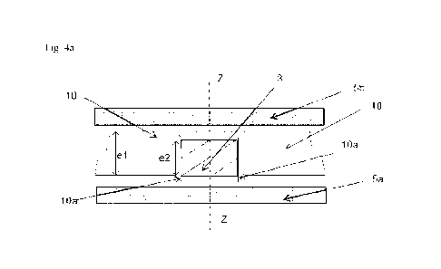
Figure 4a shows a sectional view of the same support matrix portion as in
Figure 3d at the
start of the assembly step in a particular embodiment.
Figure 4b shows a sectional view of the same support matrix portion as in
Figure 3d during
the assembly step in a particular embodiment.
Figure 4c shows a sectional view of the same support matrix portion as in
Figure 3d at the end
of the assembly step in a particular embodiment.
Figure 5 shows a top view of one embodiment of an analysis chip.
Figure 6 shows a multiplexed analysis device comprising two analysis chips.
In the drawings, identical references designate identical or similar objects.
CA 03197100 2023- 5- 1
8395685
10
FIG. 7 represents a top view of an embodiment of an analysis chip support
matrix, in which
the through holes have different shapes.
FIG. 8a presents a photograph obtained with a binocular magnifying glass
(Zeiss, Stemi SV8
model) of a biological sample analysis chip 1 cut out along a plane orthogonal
to the upper
and lower faces of the chip and containing a diameter of the circular section
of a cylindrical
through hole.
FIG. 8b reproduces a photograph of an analysis chip obtained with a method of
the prior art
implementing a Xerox Solid Ink printer, the diameter of the analysis pads
being of the order
of 500 micrometers.
Figure 8c presents a photograph of the analysis chip of Figure 8b obtained
with a binocular
magnifying glass (Zeiss, model Stemi 5V8, magnification x64).
FIG. 8d presents a photograph of the analysis chip of FIG. 8a obtained with a
binocular
magnifying glass (Zeiss, Stemi SV8 model, magnification x64) obtained by the
method
according to the invention, in which the analysis material is nitrocellulose,
the backing
material of the black paper coated with wax, the diameter of the analysis pads
being equal to
500 micrometers.
FIG. 9 presents a photograph of an analysis chip obtained with a binocular
magnifying glass
(Zeiss, Stemi 5V8 model, magnification x64) obtained by the method according
to the
invention, in which the analysis material is nitrocellulose, and the support
material is brass,
the diameter of the analysis pads being equal to 500 micrometers.
DETAILED DESCRIPTION
The invention relates to a method for manufacturing a biological sample
analysis chip 1
intended to be implemented in isolation or in an analysis device 7. The
analysis device 7 - or
the biological sample analysis chip 1 on its own - makes it possible, for
example, to carry out
analyzes of biological liquids such as blood or a liquid fraction of blood
(plasma, serum), the
urine, saliva, etc.
The analyzed liquid can also be a reaction medium comprising bio-molecules
such as
antibodies or proteins.
The notion of analysis of a biological sample must therefore be understood in
the broad sense,
i.e. it is an analysis involving at least one biomolecule among the reagent(s)
and/or the
analytes.
CA 03197100 2023- 5- 1
8395685
11
The biological sample analysis chips 1 can thus be used to detect and quantify
complex
biomolecules in biological media: blood, plasma, serum, organs or organ
extracts, reaction
medium in which complex biomolecules are produced ( antibodies, proteins).
In particular, the biological analysis can be an immunological test such as an
[LISA
("Enzyme-Linked ImmunoSorbent Assay") test.
The biological sample analysis chips 1 can still be implemented in the field
of the food
industry for the search for pathogenic agents, for example during health
checks.
The method for manufacturing a biological sample analysis chip 1 according to
the invention
comprises:
- the provision of a support matrix 10 formed in a solid material, called
"support material",
having a lower surface and an upper surface and in which at least one through
hole 11 has
been formed extending between its lower and upper surfaces;
- the supply of at least one pad 3 cut from a sheet of a second porous
solid material, called
"analysis material", the at least one pad 3 having a lower surface and an
upper surface;
- the insertion of at least one pad 3 in the at least one through hole 11
of the support matrix 10
by translation of the at least one pad 3 in the direction normal to the lower
and upper surfaces
of the matrix 10;
- cold mechanical assembly, at a temperature below the melting temperatures
of the support
and analysis materials, during which a pressing force in the direction normal
to the lower and
upper surfaces of the matrix 10 is exerted on at least a portion of the matrix
10 which adjoins
the at least one pad 3 inserted into the matrix 10 and/or on at least one of
said lower and upper
surfaces of the at least one pad 3 inserted into the matrix 10.
The biological sample analysis chip 1 obtained at the end of the process
comprises:
- a matrix 10 formed in a solid support material, in which at least one
through hole 11 has
been formed;
- at least one pad 3, cut from a sheet of solid and porous analysis
material and inserted into the
at least one through hole 11, the at least one pad 3 being crimped on at least
one of its upper
and lower surfaces by matrix 10.
The biological sample analysis chip 1, which can be observed in a particular
embodiment in
FIG. 5, therefore comprises a support matrix 10 formed in a solid material of
thickness el in
which one or more through holes 11 were formed. A particular embodiment of the
support
matrix 10 is shown in Figure 1. Another particular embodiment of the support
matrix 10 is
represented in FIG. 7. As shown in Figure 2, the support matrix 10 is formed
by cutting out a
base part 21, of suitable shape for the analysis device in which it is
intended to be used or else
CA 03197100 2023- 5- 1
8395685
12
for its use in isolation. The base part 21 is for example a rectangular or
square parallelepiped
cut from a support strip 2 of a solid material, later called "support
material", having a lower
surface and a flat upper surface parallel to each other.
A base part 21 cut from the support strip 2 to form a support matrix 10 can be
a parallelepiped
and have a width Li of between 5 mm (5 millimeters) and 50 mm and a length L2
of between
mm and 50 mm.
In a particular embodiment, the support matrix 10 is formed in an analysis
material of
constant thickness el between the lower surface and the upper surface, these
surfaces being in
this case flat and parallel to each other.
The thickness el of the support strip 2 is then constant and identical to that
of the cut part 21.
It is preferably smaller, for example by at least a factor of ten, than the
other dimensions
(length Li and width L2) of the cut part 21.
The support strip 2 can for example have a width L3 either identical to or
slightly greater than
the width Li of the support matrix 10, or for example greater than twice the
width Ll.
In the latter case, it is possible to cut out several base parts 21 in the
width of the support strip
2.
The width L3 of the support strip 2 is thus for example between 5 mm and 50
mm.
The length L4 of the support strip 2 can be greater, or even much greater,
than the length L2
of the part 21. The length L4 for example greater than 1 m or even 10 m.
In this way, it is possible to successively cut out several basic parts 21 in
the support strip 2.
The cutting of a base part 21 can for example be carried out by means of a
cutter in which the
support strip 2 is inserted.
If the support strip 2 is long enough, the cutting of the base parts 21 can be
automated, the
support strip 2 being translated by an adequate distance between two
successive cuts of a base
part 21.
The thickness el of the support strip 2 (and of a base part 21 cut from this
support strip 2) can
be less than 1 mm, less than 0.15 mm, or even less between 0.1 mm. For
example, the
thickness el of the support strip can be equal to 0.06 mm.
In a particular embodiment, the support strip 2 has a width of 20 mm and a
length of 25 m for
example. The width and length can be changed according to the type of analysis
chips 1 to be
manufactured. The thickness of the support strip 2 can be equal to 0.12 mm,
i.e. the current
thickness of the filtering membranes (generally made of nitrocellulose) formed
in the analysis
material, but it could also be of the order of 0.10mm.
CA 03197100 2023- 5- 1
8395685
13
In a particular embodiment, a base part 21 is a square filtering membrane with
sides of 20
mm.
The support strip 2 can in particular be made of metal, for example steel,
copper or brass. The
support strip 2 can, in an alternative embodiment, be made of plastic. By way
of non-limiting
example, the plastic material can be polyethylene, polyvinyl chloride,
polystyrene,
polymethyl methacrylate, polypropylene or any other plastic material commonly
used in the
field of biochemical analyses. It may have undergone a surface treatment or be
UV resistant.
The support material may also contain vegetable fibres, for example cellulose.
It may in
particular be paper.
The support material is strong but not necessarily rigid. The support strip 2
can thus have a
certain flexibility, provided that the support strip 2 or a support matrix 10
formed from this
support strip 2 can be manipulated and moved for the preparation of the
analysis chips 1, in
particular without tearing , including the case where the preparation of the
support matrix 10
is automated. By way of example, Rex Copy A4 photocopier paper distributed by
Mondie,
with a weight of 80 g/m2, available on the priority date of this patent
application, is suitable
for the invention.
In the case where the support strip 2 is flexible, the material is
sufficiently rigid for the upper
and lower surfaces to be effectively flat when the lower surface is, at least
locally, simply
placed on a flat support.
In one embodiment, the support material is rigid enough to allow the cutting
of one or more
base parts 21 by means of a cutter. In a base part 21 of support material, at
least one through
hole 11 is formed through the material in its thickness, that is to say along
the direction
normal to the lower and upper surfaces of the part 21.
In a particular embodiment, a through hole 11 is formed by means of a punch
42, as shown in
Figures 3a1 (at the start of drilling), 3a2 (during drilling), and 3b (just
before the injection
step that follows the drilling step, described later). In this embodiment, the
punch 42 is
translated along the direction of the axis of the future through hole 11, so
as to pierce the
support matrix 10. A dedicated cutting guide 4 can be placed under support
strip 2. The stroke
of the punch 42 through the cutting guide 4 is adjusted so as to allow the
ejection of a pad 10b
from the support strip 2, as can be seen in Figures 3a1 and 3a2.
The punch can then be moved in the opposite direction so as to release the
support matrix 10
then comprising one or more through holes 11.
In a particular embodiment, the through holes 11 are formed on the locations
corresponding to
the future base parts 21 in the support strip 2 before one or more base parts
21 are cut out.
CA 03197100 2023- 5- 1
8395685
14
In another embodiment, the through holes 11 are formed in a base part 21
already cut out.
Alternatively, the through holes 11 are formed at the same time as the part 21
is cut, for
example by means of a cutter of suitable shape.
The shape of the through holes 11 can be chosen according to the needs of the
analysis. For
example, the surface delimiting the interior of a through hole 11 is a
cylinder whose
generatrix is parallel to the direction normal to the lower and upper surfaces
of the part 21,
direction which will be referred to below as the "axis of the hole". 11. For
example, the
through holes 11 are cylinders of revolution.
In the embodiment represented in FIG. 7, one of the through holes 11 can be
analyzed as
formed by two through sub-parts of circular section ha and 11b, connected by a
channel 11c.
Once the pads of analysis material have been inserted as described below, it
will thus be
possible to deposit the sample to be analyzed in the well corresponding to the
first "sub-hole"
and to let the sample diffuse from the sub-part ha to subsection 11b. In this
case, it is
possible to use the analysis chip to perform a lateral flow type test.
The characteristic dimensions of a through hole 11 in a direction of the upper
or lower surface
of the part 21 in which the through hole 11 is formed may be less than 1 mm.
For example, a support matrix 10 can comprise 9, 12, 24, 48 or 96 holes (or
wells) 11 having
the shape of cylinders of revolution with a diameter dl of the order of 300 to
800 gm
(micrometers), two successive through holes 11 being spaced apart by a
distance d2 of the
order of 100 to 250 gm.
Optionally, a cutout or a reference mark 12 is formed on the support matrix 10
so as to be able
to identify its orientation, in particular during an analysis which will be
carried out later. This
arrangement makes it possible to differentiate the through holes 11 from each
other when the
support matrix 10 has elements of symmetry.
At the end of the step of drilling a through hole 11, the lower and upper
faces of the support
material are no longer strictly flat near the lower and upper bases of the
through hole 11 but
an overhang 10a of support material is formed over the entire circumference of
a through hole
11 on the side of the underside of the support material, due to the resistance
that the support
material opposes to its cutting. This overhang 10a, which can be seen in
Figure 3a2, will be
used during the subsequent assembly step.
In the first step of the method according to the invention, a support matrix
10 is therefore
provided, formed in a support material of constant thickness el between a
lower surface and
an upper surface in which one or more holes 11 passing through it in its
thickness have been
formed.
CA 03197100 2023- 5- 1
8395685
15
In a second step, a sheet 6 of constant thickness, denoted e2, of a second
porous solid material
called "analysis material" is provided, having an upper surface and a lower
surface.
The analysis material is intended to receive on one of its lower and upper
surfaces a liquid
sample to be analyzed or filtered, which must then be able to flow towards the
other of these
surfaces, either spontaneously by simple diffusion, or due to forced
circulation of the liquid.
The analysis material can therefore be a porous material such as paper, in
particular filter
paper, that is to say paper with a high alpha-cellulose content (in particular
more than 90%,
95%, or even 98% of alpha-cellulose).
The analysis material can also be nitrocellulose.
Nitrocellulose has a good affinity for small proteins, peptides or nucleic
acids. It is therefore
particularly well suited for biological analyses. These examples should not,
however, be
considered as limiting.
The material for analysis can be chosen in particular according to its
resistance to humidity,
its filtration rate, its breaking strength, its rate of capillary rise or its
resistance to the passage
of air.
In the case where the liquid to be analyzed mainly contains water, the
analysis material is
preferably hydrophilic, so that the liquid to be analyzed wets the surface of
the analysis
material. In this case, the support material can be hydrophobic.
In the following, we will consider that a material is hydrophobic if the water
does not wet the
material, i.e. if the angle between a drop of water and the surface of the
material on which the
drop is deposited is strictly greater than 900. Otherwise, the analytical
material is hydrophilic.
Alternatively, the analysis material can be hydrophobic and the support
material hydrophilic.
The analysis material can be an isotropic or anisotropic filter membrane. In
particular, it may
be an organic filter membrane, that is to say a membrane comprising an organic
polymer such
as cellulose acetate, a polysulfone or a polyamide.
The thickness e2 of the analysis material can be close to the thickness el of
the support
material. The thickness e2 can be greater than, equal to or less than the
thickness el.
In the case where the support material is nitrocellulose, the thickness e2 of
the analysis
material may thus be of the order of a few hundreds, or even a few tens of
micrometers, for
example 50 gm to 150 gm.
In a third step, called injection, a portion of the analysis material, called
pad 3, is inserted into
at least one through hole 11 of the support matrix 10, so that the pad 3
closes this hole 11.
A pad 3 is therefore complementary to a hole 11 in which it must be inserted
over at least part
of the thickness of the support material. In other words, if the surface
delimiting the interior of
CA 03197100 2023- 5- 1
8395685
16
a through hole 11 is a cylinder whose generatrix is parallel to the direction
normal to the
lower and upper surfaces of the part 21, a pad 3 which can be inserted therein
is a cylinder
whose generatrix is parallel, after insertion, to the axis of the through hole
11 whose base has
the same shape as the base of the through hole 11.
The term "pad" should therefore not be interpreted in a limiting manner in
terms of shape. It
was chosen in relation to the easiest embodiment to implement, that is to say
the one for
which the through hole 11 and the pad 3 are cylinders of revolution.
Thus, in the embodiment shown in Figure 7, the pad 3 inserting into the
through hole 11
formed of two sub-parts 11a, lib and a channel 11c will have the complementary
shape
adapted to fill the sub -parts 11a, 11b and 11c, while the pad 3 fitting into
the cylindrical
through hole 11 will be cylindrical.
The height of the pad 3 can in all cases be equal to the height of the hole 11
(as seen in the
sectional view along a plane containing the axis of the through hole 11 shown
in Figure 4c) or
different from this (see FIG. 9 which shows an analysis chip 1 according to
the invention, the
support material of which is brass coated with Le Parfait food paraffin
(reference 365 [MB
44 026, packaging 250g) and the material for nitrocellulose analysis
(Reference: Amersham
Protran Premium pores 0.45pm NitroCellulose, GE Healthcare Life Science
Nitrocellulose
Bloting Membrane Nucleic acid and Protein application Catalog No 10600008).
The interlocking carried out during the insertion step is obtained only by
translation of the pad
3 along the axis of the through hole 11. For example, if the through hole 11
was formed in the
base material using a punch, the support matrix 10 may remain in place under
the punch 42
after the hole 11 has been drilled.
A sheet 6 of analysis material is then placed above the pierced support matrix
10, as shown in
FIG. 3b and the punch 42 is again moved along the axis of the hole at a
distance at least
slightly lower than that which made it possible to drill the hole 11.
In this way, the punch 42 cuts out the pad 3 to be inserted and drives it
along its path inside
the through hole 11, but without it coming out completely from the through
hole 11 on the
side of the lower surface of the support matrix 10 and so that it is
positioned above at least
part of the overhang 10a.
At the end of this insertion step, the pad 3 is therefore well fitted, at
least over part of its
height, in the through hole 11.
The choice of the stroke of the punch makes it possible to position the pad 3
at a chosen
height in the concerned through hole 11, for example so that the lower base of
the pad 3 is in
CA 03197100 2023- 5- 1
8395685
17
the same plane as the lower surface of the support matrix 10 or at least the
lowest points of the
overhang 10a, as shown in Figure 3c.
It is also possible to use a punch dedicated to the insertion step, for
example in an
embodiment in which the production of the matrices is automated and carried
out much
before the insertion step.
It is also possible to provide one or more pads 3 cut out in advance, for
example by means of
a cutter or any other precision cutting tool and to insert them into the
through hole 11 which
corresponds to them by a vertical translational movement.
The embodiment in which the cutting and the insertion are carried out
consecutively with the
same punch has the advantage of the simplicity of the positioning of the pads
and the speed of
carrying out this step.
In the latter case, a punch tool and two corresponding counter pieces are
provided in order to
be able to suitably perforate the support strip 2 and thus make the wells (or
even "spots", or
even through holes 11) in the support strip 2 first. This tool may in
particular be made of steel
so that its rigidity and its resistance over time are guaranteed. The
dimensions of this tool will
be adapted to the types of analysis chips 1 to be produced.
In a particular embodiment, 25 through holes 11 of 500 micrometers in diameter
are formed
spaced 200 micrometers apart, contained in a 6mm x 6mm square placed in the
center of a
base part 21 in the shape of a square of support material (20 x 20mm ).
The punch tool will therefore have 25 punches with a diameter of 500
micrometers. For other
configurations of the biological sample analysis chip 1, the punches used for
all the through
holes 11 or for part of these through holes 11 may have different diameters.
The diameter (or
a characteristic dimension in the case where the section of the through hole
11 is not circular)
of the punch may thus be less than 1000 micrometers, less than 900
micrometers, less than
800 micrometers, less than 700 micrometers, less than 600 micrometers, less
than 500
micrometers, less than 400 micrometers, less than 300 micrometers, less than
200
micrometers, less than 150 micrometers, less than 100 micrometers .
The "punches as well as two counter-pieces" assembly can be fixed under a
press, between
the jaws 5a and 5b of this press. The support strip 2 unrolls automatically in
the lower part of
the first counterpiece and adjusted in the middle of this "punch; first
counterpart; second
counter part" in order to make wells (through holes 11) automatically by
simple movement
from top to bottom in the intended place. As soon as this first stamping is
finished, the strip of
analysis material is introduced above the second counterpart, once the punch
has returned to
the "high" position. A second stamping (this time of the analysis material,
forming the filter
CA 03197100 2023- 5- 1
8395685
18
membrane) is then carried out, allowing the cutting of pads 3 of this analysis
material, for
example a filter membrane.
The downward stroke of the punches of the cutter can then, for example, be
adjusted for this
second stamping in such a way that in the low position, the punch stops at the
start of the
already pierced support strip 2. In this way the punches will push the freshly
cut pads 3 of
analysis material, for example nitrocellulose, and insert them into the
through holes 11 so as
to fill, at least partially, these through holes 11 of the support matrix (or
membrane ).
This being done, the strip can advance under a second press which has the
function of
crimping the pads of analysis material, for example of nitrocellulose, in the
support strip 2, or
at least in the support matrix 10, by a shock (pressure) which can be exerted
on the entire
surface of the membrane in order to properly block the pads in the support
strip, as described
below. The strength of this pressure or (shock) can be determined by testing.
Whatever the embodiment chosen for the injection step, the insertion is done
if possible only
by translation of the pad 3 along the axis of the concerned through hole 11,
so as to keep the
properties of the analysis material unchanged during this step. In particular,
the method
according to the invention has the advantage of not implementing any step
which could
introduce an anisotropy of the properties of this material and thus degrade
the precision and
sensitivity of the analysis, as discussed previously for a step of lamination.
Furthermore, in the case where the support matrix 10 comprises at least two
pads 3 inserted in
at least two different through holes 11, these pads 3 are not connected by a
portion of analysis
material. Consequently, if the analysis material is chosen sufficiently
different from that of the
support material, it is unlikely that the molecules which adsorb on a given
pad 3 risk
migrating to a neighboring pad 3.
In the same way, if the liquid to be analyzed wets the pad 3, by choosing a
support material of
hydrophobicity different from that of the analysis material, it is possible to
limit, or even
avoid, the lateral diffusion of the liquid to be analyzed. from a pad 3 to the
support material -
and possibly to another pad 3.
Thus, if the sample to be analyzed is an aqueous solution, a hydrophilic
analysis material and
a hydrophobic support material can be chosen.
It is also possible to envisage a hydrophilic support material and pads 3 of
hydrophobic
analysis material in the case where the sample to be analyzed is an organic
phase immiscible
with water.
This step of injection only by a translational movement along the axis of the
hole 11 makes it
possible, while respecting the physico-chemical properties of the support and
analysis
CA 03197100 2023- 5- 1
8395685
19
materials, to obtain at the end of the complete process an biological sample
analysis chip 1
allowing qualitative analyzes of high sensitivity.
In a particular embodiment, the support matrix 10 has at least two through
holes 11 and a first
pad 3 is inserted into one of the through holes 11 before another pad 3 is
inserted into another
through hole 11.
In this case, at least two different cutters are consecutively used.
This embodiment makes it possible to insert into two different through holes
11 two pads 3
formed in different analysis materials.
For example, it is possible to prepare at least two sheets of initially
identical analysis material
but each having undergone a different bio-functionalization step, in
particular by adsorption
of two different antigens.
A pad 31a on which a first antigen has been adsorbed can be inserted into a
first through hole
11 of a support matrix 10 and another pad 31b on which a second antigen has
been adsorbed
can be inserted into a second through hole 11 of the support matrix 10.
In this case, a cut-out or reference mark 12 optionally formed on the support
matrix 10 can
make it possible to identify the positions of the various test sites.
In the case where the management of the bio-functionalization is done on the
scale of the
sheet of material for analysis, rather than pad 3 by pad 3 on a given chip
and/or on successive
chips, it is possible to produce identical analysis chips in series with a
high yield, which
present identical analytical qualities, making it possible to work under
conditions of
satisfactory repeatability, even reproducibility. The limit of quantification,
i.e. the smallest
concentration or content of the analyte that can be quantified, with an
acceptable uncertainty,
under the experimental conditions described in the method, can be considered
constant for a
series of analysis chips produced automatically from the same sheets of
analysis material.
This quantification limit is easier to control in the case of a sheet than in
the case of a single
pad 3 in which the edge effects will play an important role.
It is also possible to orient the probe molecules used for the
functionalization so that the sites
on which the molecules to be tested can bind are oriented along the axis of
the hole. This
arrangement makes it possible to further increase the sensitivity (or the
limit of quantification)
of the analysis. The probe molecules may in particular be those described in
patent
EP3591024B1 (inventors Wong Ka-Leung, Goetz Joan et al.) filed on 07/05/2018,
namely
ultra-bright luminescent lanthanide nanoparticles comprising terbium.
Quantification limits of
the order of a few atoms per microliter of liquid to be tested are thus
achieved.
CA 03197100 2023- 5- 1
8395685
20
In a particular embodiment, the analysis material is not functionalized and is
kept in its native
structure at the level of the pads 3. In this way, a so-called "filtering" pad
32 is formed, the
only function of which is a filtration function.
If one superimposes a biological sample analysis chip 1 comprising filtering
pads 32 and a
biological sample analysis chip 1 comprising functionalized pads 31 (31a, 31b,
etc.) so that
each filter pad 32 is placed above a functionalized pad 31, so that all the
fluid which passes
through a filtering pad 32 reaches the corresponding functionalized pad 31, it
is thus possible
to analyze a blood sample without prior centrifugation, the red blood cells
being retained by
the filtering biological sample analysis chip 1 while the serum or plasma
passes through this
chip to then be analyzed by the functionalized biological sample analysis chip
1 .
This arrangement therefore saves considerable time and material for such
analyses. In a
particular embodiment, one or more pads 3 can be calibration pads 33 of the
biological
sample analysis chip 1.
In a particular embodiment of the injection step, a pad 3 is cooled just
before injection to a
temperature slightly lower than that of the support matrix 10 into which it is
to be inserted. In
this way, insertion is facilitated but simultaneously with insertion, the pad
3 heats up and
therefore expands, preferably enough to ensure that it is held in place at the
end of the
injection step.
This embodiment is advantageous when the support material has a particular
rigidity, as is the
case for certain plastic materials. After the injection step, a pad 3 is
nested in a through hole
11, so that it is above at least a fraction of the overhang 10a, as shown in
Figure 3d.
If the biological sample analysis chip 1 is at rest, the pad(s) 3 remain in
place in the through
hole(s) 11. The biological sample analysis chip 1 could therefore possibly be
used as it is.
However, insofar as no chemical or heat treatment is implemented at the
injection step, it is
not certain that the pads 3 remain in place, for example due to the flow of a
sample liquid,
forced or under the effect of gravity.
A fourth step, called assembly, is therefore implemented in such a way as to
secure the
assembly of the pad(s) 3 with the support matrix 10.
To do this, a pressing force along the axis of the through hole 11 is exerted
on the analysis
chip by means of two jaws 5a, 5b of a clamping system placed below and above
the bases of
the pad 3 and at least a fraction of the support matrix 10 which adjoins it.
By fraction of the support matrix 10 which adjoins a pad 3, it is meant the
fraction of support
matrix which is in the immediate vicinity of this pad 3 and delimits the
through hole 11 in
CA 03197100 2023- 5- 1
8395685
21
which it is inserted. In particular, the fraction of the support matrix 10
which adjoins a pad 3
can include all or part of an overhang 10a.
In a particular embodiment, the fraction of support matrix 10 which adjoins a
cylindrical pad
3 along the axis of a through hole 11 and with section S can be at least that
which is located in
the cylindrical volume with axis the axis of the through hole 11 and of
section S', S' being
obtained by a dilation with a ratio greater than 1 and centered on the
intersection of the axis of
the through hole and of the section S. For example, if a pad 3 is cylindrical
with a diameter
equal to 100 micrometers, it will be possible to exert a pressing force on the
portion of the
support matrix located in the cylinder with the same axis as the pad 3 once
inserted and with a
diameter at least equal to 101 micrometers, at least equal to 102 micrometers,
at the at least
equal to 103 micrometers, at least equal to 104 micrometers, at least equal to
104
micrometers, at least equal to 110 micrometers, at least equal to 120
micrometers, at least
equal to 130 micrometers, at least equal to 140 micrometers, 150 micrometers.
If several pads 3 are inserted into the support matrix 10, the same reasoning
is applied to each
of the pads 3.
In a particular embodiment, the pressing force is exerted by means of the
clamping system on
the whole of the upper surface and/or of the lower surface of the support
matrix 10.
The pressing force can then be exerted by means of the clamping system, the
jaws 5a, 5b of
which, when they approach, come to grip at least a portion of the support
matrix 10 which
adjoins a pad 3 so that the portion of the support matrix 10 crimps the upper
surface and/or
the lower surface of the pad 3.
In this embodiment, it is understood that the pressing force may not include a
component in a
direction normal to the axis of a through hole 11. The direction of the
pressing force is thus
collinear with the axis of the through hole 11, so that no non-native
anisotropics are
introduced into the support and analysis materials in a direction non-
collinear with the axis of
the through hole. 11. This arrangement makes it possible in particular to
precisely control the
quantification limit of the analysis chip.
As a variant, the pressing force can then be exerted by means of the clamping
system, the
jaws 5a, 5b of which, when they approach, grip at least a portion of the lower
surface and/or
the upper surface of a pad 3 which would protrude of the support matrix 10, so
that the upper
surface and/or the lower surface of the pad 3 folds over the matrix 10 and
crimps it.
The mechanical assembly step can therefore result in a crimping of at least
one pad 3 on at
least one of its lower and upper surfaces by the matrix 10. For simplicity, we
consider in this
document, the formulation of the previous sentence covers the two possible
scenarios:
CA 03197100 2023- 5- 1
8395685
22
crimping of the matrix 10 by the pad 3 or crimping of the pad 3 by the matrix
10, the technical
effect being in the two cases the same, namely an assembly of at least one pad
3 to the matrix
resistant to a stress exerted along the axis of the through hole 11.
If a pad 3 is initially of height e2 lower than the height el of the through
hole 11, assuming
that the lower base of the pad 3 was placed higher than at least a fraction of
the overhang 10a,
the pressing force which is exerted along the axis of the hole makes it
possible to carry out a
crimping as shown in Figures 4a (at the start of the assembly step), 4b
(during assembly) and
4c (at the end of the assembly step): the thicknesses el of the support
material and e'2 of the
pad 3 at the end of the assembly step are less than their thicknesses el and
e2 before this step,
and the overhang 10a has been folded over the entire circumference of the pad
3 so that the
support material forms a collar above and below the pad 3. In a particular
embodiment, the
pad 3 is crimped over the entire circumference of its lower base by the
support matrix. In a
particular embodiment, the pad 3 is crimped over the entire circumference of
its upper base by
the support matrix. Pad 3 can be crimped simultaneously over the entire
circumference of its
lower base and over the entire circumference of its upper base.
Consequently, the pad 3 is assembled more solidly to the support matrix 10
after this
assembly step than before and is more resistant to tearing due to a force
exerted from the
upper face towards the lower face of this pad. During the assembly step, the
fact of exerting
only a mechanical action, the latter being moreover exerted in the direction
of the axis of a
through hole 11 and possibly distributed uniformly on the bases of a pad 3
makes it possible
to maintain the uniformity and the isotropy of the physico-chemical properties
of the analysis
material in the planes normal to the axis of the concerned through hole 11.
The pressure exerted during this assembly step can be chosen according to the
mechanical
resistance of the assembly necessary for the analyses.
For example, it is possible to obtain a biological sample analysis chip 1
whose pads 3 remain
in place when a fluid passes through them in a forced manner by means of a
pressure
difference between the upstream face and the downstream face of the pad lower
than 100
mbar (millibar); less than 200 mbar; less than 300 mbar; less than 400 mbar;
lower than 500
mbar; less than 600 mbar; less than 650 mbar; less than 700 mbar; lower than
750 mbar; less
than 800 mbar; less than 850 mbar; less than 900 mbar; lower than 950 mbar;
less than 1.00
bar.
The upstream and downstream faces are understood here relative to the
direction and direction
of fluid flow.
CA 03197100 2023- 5- 1
8395685
23
It is considered that an analysis pad 3 "remains in place" if, at the end of
the analysis, this
analysis pad still completely closes the through hole 11 in which it was
inserted. In particular,
a shift of the pad 3 in the direction of the axis of the through hole due to
the pressure
difference between its upstream and downstream faces can occur without
contesting the
quality of the analysis carried out by means of the biological sample analysis
chip 1.
If the analysis pad 3 "stays in place" when a pressure difference exists
between its upstream
and downstream faces, it will then be said that the biological sample analysis
chip 1 "resists"
the corresponding relative vacuum.
The upper face of a pad 3 can, in a particular embodiment, simply be subjected
to atmospheric
pressure and the lower face placed under depression. In this way, an analysis
device
comprising a biological sample analysis chip 1 can be implemented with forced
circulation of
fluid, which makes it possible to control the contact time of the sample to be
tested with a pad
3 and therefore the reproducibility of the analysis.
This arrangement also makes it possible to reduce the duration of the
analyses.
In particular, the forced circulation of the sample to be tested avoids, or at
least accelerates,
the washing steps generally necessary to eliminate the fraction of the test
sample which has
not reacted as well as the molecules which have adsorbed in a non-specific way
on the
membrane. For example, it is possible to perform a blood test over a period of
30 minutes
between the deposit of the sample (not centrifuged) and the result of the
analysis. A
conventional [LISA test requires a much longer time, usually 12 to 24 hours.
The mechanical assembly is carried out in the solid phase, and at a
temperature below the
melting temperatures of the support and analysis materials. This assembly
therefore does not
implement a process of the welding type, for example, which could denature the
materials or
modify their physical structure.
Thanks to the assembly method according to the invention, there is no
possibility of migration
of the support material or of a solvent towards the analysis material and vice
versa, so that the
analysis material retains from the properties its native properties, that is
to say its properties
before assembly with the support material. In addition, the interface between
the support
material and the analysis material is clean, as can be seen in Figure 8a on
which a photograph
of a section of a biological sample analysis chip 1 in a plane containing the
axis of a
cylindrical through hole 11 and a diameter of its section is presented. In
this case, as in the
case of FIG. 8d, the support material is the black paper distributed by the
company Mondie,
with a weight of 80 g/m2, available on the priority date of the present patent
application. It
has been impregnated with Le Parfait food paraffin (reference 365 EMB 44026,
packaging
CA 03197100 2023- 5- 1
8395685
24
250g) so that a support matrix pierced with 9 holes weighs 55mg before
impregnation and
77mg after impregnation. The analysis material is nitrocellulose (Reference:
Amersham
Protran Premium pores 0.45pm NitroCellulose, GE Healthcare Life Science
Nitrocellulose
Blotting Membrane Nucleic acid and Protein application Catalog No 10600008).
The diameter of the through holes is 500 micrometers. The photographs in
Figures 8a, 8c and
8d were obtained with a binocular magnifying glass (Zeiss, model STEMI SV8,
magnification
x64). It is further noted that in FIGS. 8d and 9 that at the magnification of
the binocular loupe,
the analysis material and the support material do not diffuse towards each
other. Finally, it is
observed in FIGS. 8a, 8d and 9 that the process for preparing the analysis
chip makes it
possible to obtain wells whose edges are clean and this with dimensions of the
order of ten or
hundred of micrometers.
The situation is different in the case of Figures 8b and 8c, which show a
photograph of an
analysis chip obtained with a printing process using a solid ink printer whose
wells have a
diameter of 500 micrometers. It is observed in this photograph that the ink
used to form the
wells diffuses towards the analysis material, so that the section of a well is
not really circular,
which affects the precision of the analysis as well as to its reproducibility,
the contours of two
different wells never being strictly the same.
The white spots present (other than the pads 3) in the support material of
FIG. 8c correspond
to areas in which the ink forming the pellets has diffused. The support
material has therefore
lost its native properties as a result of printing and the quantity of ink
forming a given pad is
therefore not known. The reproducibility and precision of an analysis on a pad
is therefore
difficult to control with this method of the prior art.
It will be noted in figure 8d, whose magnification is substantially equal to
that of figure 8c,
that the grain of the support material is observed but no diffusion of the
analysis material
towards the support material. The same is true in the case of Figure 9.
The method according to the invention therefore makes it possible to obtain
finer control of
the analysis pads 3 than the methods of the prior art.
At the end of the assembly step, it is possible to carry out a
functionalization step of one or
more pads 3.
By way of example, a chosen volume of a solution of probe molecules can be
deposited with
a pipette or a micropipette, optionally in an automated manner, on one or more
pads 3.
The bio-functionalization of a biological sample analysis chip 1 consists in
particular in
attaching a capture molecule (for example an antibody to detect an antigen)
targeting the
complex biomolecule to be detected and quantified in the biological liquid to
be analyzed.
CA 03197100 2023- 5- 1
8395685
25
In a particular embodiment, a roll of analysis chips 1, in which the pads 3
are already in place,
can be placed on a "spotting" machine. The roll is unrolled to scroll the
strips of analysis
chips ion a filter plate connected to a vacuum pump. The injection head of the
spotting
machine deposits, for example, in 2 or 3 injections, a volume of the order of
10 L of a
solution containing the captured molecule, for example, at a concentration of
10 to 30 pg/mL.
The suction vacuum can be chosen to allow a slow filtration over a time of
approximately 20
seconds of the 10 jiL of solution. All of the pads 3 of each biological sample
analysis chip 1
can thus be processed in the same way.
A second application can then be carried out under the same conditions but
with a solution of
BSA (Bovine Serum Albumin), for example at a concentration of around 100
pg/mL. This
solution makes it possible to saturate the polar sites of the filtering
biological sample analysis
chip 1 to avoid non-specific bonds between the biomolecule which will be
detected and the
analysis surface, for example of nitrocellulose, of the biological sample
analysis chip 1.
After incubation of the roll of analysis chips 1, for example at 37 degrees
Celsius for 30
minutes, the analysis chips 1 can be separated from each other with a cutting
tool so as to
obtain isolated analysis chips all of the same dimensions. At the end of the
assembly step, and
possibly after functionalization, it is therefore possible, if this has not
already been done
previously, to cut the base parts 12 to detach the analysis chip(s) 1 from the
support strip 2. A
biological sample analysis chip 1 obtained by the method according to the
invention can be
stored for several months at room temperature, preferably in a dry atmosphere
(for example
under airtight and watertight protection). In particular, analysis chips 1 can
be stored at 20 C
+/- 5 C for at least 1 month, at least 2 months, at least 3 months, at least 4
months, at least 5
months, at least 6 months, at least 7 months, at least 8 months, at least 9
months, at least 10
months, at least 11 months, at least 12 months without altering their analysis
properties. In
particular, a reference test on a reference biological sample will
statistically give the same
concentration of the analyte sought (same mean and same standard deviation) on
a batch of
biological sample analysis chips 1 just after manufacture and after storage at
20 C +/- 5 C
under airtight and watertight protection (e.g. blister pack) for at least 1
month, at least 2
months, at least 3 months, at least 4 months, at at least 5 months, at least 6
months, at least 7
months, at least 8 months, at least 9 months, at least 10 months, at least 11
months, at least 12
months.
The last two steps (injection and assembly) make it possible to control the
properties of the
support material independently of the properties of the analysis material and
vice versa, unlike
the methods of the prior art.
CA 03197100 2023- 5- 1
8395685
26
Typically, if the support material is formed from a metal plate, this metal
plate can be
rendered hydrophobic beforehand. For example, a surface treatment, such as a
coating with a
natural or synthetic wax, can be implemented.
In the known methods, such a treatment limits the analytical qualities of the
chip, since the
wax can migrate in an uncontrolled manner from the support material to the
analysis material,
for example upon a step of heating, chemical treatment or rolling. The wax (or
any other
chemical compound used for the surface treatment) can then interfere with the
analysis.
Among other things, fluorescence quenching phenomena are observed, which
reduce the
sensitivity of the analysis when fluorescent probe molecules are used. In the
invention, the
assembly step does not lead to such uncontrolled diffusion or migration of the
wax. Certain
embodiments even make it possible to avoid an uncontrolled diffusion or
migration of
chemical species from the analysis pads 3 or towards these pads 3. The method
according to
the invention therefore makes it possible to obtain a biological sample
analysis chip 1 whose
test zones (in other words the analysis pads 3) are formed with better
precision than with the
methods of the prior art.
This analysis is also valid for the case where pads 3 are functionalized
before the injection
step.
We can therefore see the advantage of the injection step according to the
invention, which
makes it possible to limit the interference between the support and analysis
materials which
constitute it, and thus to obtain a biological sample analysis chip 1 of low
limit of
quantification. In addition, no solvent or heat treatment is involved in the
injection and
assembly steps of the test areas with the support matrix. These steps can be
performed using
simple tools. The process is therefore inexpensive, rapid, and not very
polluting.
Insofar as one of the materials among the support and analysis materials can
be hydrophilic, it
will be possible in a particular embodiment to work under controlled
hygrometry conditions
for one or more steps of the process, so as to keep a precise control over the
geometry and the
volume of the support matrix 10 and/or the pads 3 of a biological sample
analysis chip 1.
A biological sample analysis chip 1 obtained by the method according to the
invention can be
implemented in isolation. In this case, a sample to be analyzed can be
deposited on one or
more of the pads 3 of the chip. Or even several samples to be analyzed can
each be deposited
on one or more pads 3 different from those used for the other samples,
simultaneously or
successively.
The biological sample analysis chip 1 can, to do this, be placed horizontally,
so that a given
liquid sample to be analyzed flows from the upper face of the pad 3 on which
it has been
CA 03197100 2023- 5- 1
8395685
27
deposited towards the underside of this same pad 3, either under the effect of
gravity or under
the effect of a pressure gradient, a relative vacuum being applied on the side
of the underside
of the pad 3.
Several analysis chips 1, in particular functionalized differently from each
other, can be
superimposed in as described in application W02014/053,237A1, so that
different channels
are formed, each channel containing a single pad 3 or several pads 3, each of
the latter
belonging to a different biological sample analysis chip 1.
Such a three-dimensional multiplexed analysis device is schematically
represented in Figure
6. The analysis device 7 consists of a stack of solid support plates 72, for
example made of
polymethyl methacrylate (PM MA) or another plastic material, in which
microchannels 71 are
formed and between which analysis chips 1 are inserted.
The microchannels are aligned with each other and the analysis sites (that is
to say the pads 3)
of the analysis chips 1 are inserted between two microchannels of two
consecutive support
plates 72. It is also possible to superimpose several analysis chips 1 between
two consecutive
support plates 72. In this case, if different samples to be analyzed are
tested in the different
channels, it is possible to perform a 3D multiplexed analysis.
More simply, it is possible to provide an analysis device 7 comprising four
pillars on which
the biological sample analysis chip 1 is fixed by its four corners. These two
examples are non-
limiting. The detection of an analyte of interest can be done by an
immunological analysis of
the ELISA type: once the complex of capture molecule / biomolecule of interest
has formed
on the analysis sites (or equivalent wells) of the biological sample analysis
chip 1, a revealing
antibody is added which specifically binds to the capture molecule/biomolecule
complex. The
fluorescence or color that appears in each well is measured using a device
such as a
photomultiplier or a CMOS-type camera, coupled with a computer program that
performs the
calculations.
The invention therefore also relates to an analysis device 7 comprising at
least one biological
sample analysis chip 1.
The analysis device 7 can contain several analysis chips 1, in particular
superimposed, as
described above.
The invention further relates to a diagnostic kit comprising at least one
biological sample
analysis chip 1.
The diagnostic kit can also comprise a support for the biological sample
analysis chip 1 and/or
at least one analysis reagent. The analysis reagent may in particular contain
one or more
CA 03197100 2023- 5- 1
8395685
28
antibodies or one or more antigens with a view to implementing an
immunological test. The
analysis reagent can also be a revealer.
In the case of the present application, the term immunological test
("immunoassay") is
understood to mean a test implementing at least one antigen to detect
antibodies directed
against a pathogenic agent in a sample or at least one antibody to detect an
antigen of a
pathogen in a sample.
The analysis reagent can also be a buffer, for example a saline phosphate
buffer (PBS) or
another solution, for example a solution of bovine serum albumin (BSA).
The invention relates to the use of a biological sample analysis chip 1 for
diagnostic purposes
or for carrying out an immunological test. In particular, serological research
tests at the
quantification of antibodies of the immunoglobulin G or M type (IgG or IgM)
can be
implemented after functionalizations of the biological sample analysis chip 1
by means of the
appropriate antigen. The biological sample analysis chip 1 can also be
functionalized to
search for and quantify heat shock proteins such as the proteins of the HSP60
family by
means of a specific antibody, for example fluorescent. The apolipoprotein
ApoA1 or even
mediators of inflammation such as C-reactive protein (CRP) or the pancreatic
stabilizing
protein PSP ("pancreatic stone protein") can be sought by the implementation
of an
enzymoimmunological method on the biological sample analysis chip 1.
The invention finally relates to a device for manufacturing a biological
sample analysis chip 1
according to any one of the embodiments comprising:
- an insertion system suitable for inserting at least one pad 3 into at
least one through hole 11
of the matrix 10 by translation of the pad 3 in the direction normal to the
upper and lower
surfaces of the matrix 10
- a mechanical assembly system at a temperature below the melting
temperatures of the
support and analysis materials, adapted to exert a pressing force in the
direction normal to the
lower and upper surfaces of the matrix 10 on at least a portion of the matrix
10 which adjoins
the at least one pad 3 inserted into the matrix 10 and/or on at least one of
said lower and upper
surfaces of the at least one pad 3 inserted into the matrix 10.
The device for manufacturing a biological sample analysis chip 1 can in
particular comprise
one or more punches, each comprising one or more punches which may or may not
be
identical and whose stroke is adjustable, and one or more counter-parts.
The device for manufacturing a biological sample analysis chip 1 can be fully
automated.
LIST OF REFERENCE SIGNS
CA 03197100 2023- 5- 1
8395685
29
1: analysis chip
: support matrix
10a: overhang of support material
11: hole through the support matrix 10
11a, 11b: sub-part of a through hole 11
11c: channel connecting two sub-parts ha and lib
12 : cut! reference mark
2 : support strip
21: base part
3: pad of analysis material
31 a, b, c: functionalized pad 3
32 : filter pad
33: calibration pad
4 : cutting guide
42 : punch of a cutter
5a, 5b: jaws of a press
6 : sheet of analysis material
7 : multiplexed analysis device
71: microchannel
72 : support plate
CA 03197100 2023- 5- 1
8395685