Note : Les descriptions sont présentées dans la langue officielle dans laquelle elles ont été soumises.
Description
Title of Invention
THERMOSTAT DEVICE AND METHOD FOR MANUFACTURING THERMOSTAT
DEVICE
Technical Field
[0001]
The present invention relates to a thermostat device
and a method for manufacturing a thermostat device.
Background Art
[0002]
The thermostat device is disposed on the inlet side or
the outlet side of the vehicle engine, for example, and is
used to open and close a cooling path connecting the engine
and the radiator to control the temperature of the coolant
circulating through the engine.
[0003]
As disclosed in patent literature 1 (see Fig. 5), for
example, such a thermostat device includes a housing 60
inside which a flow path leading to a cooling path is formed,
a thermo-element 51, one end of which is inserted in the
housing 60, expanding and contracting, depending a
temperature, a valve body 52 opening or closing the flow
1
CA 03206801 2023- 7- 27
path in response to the expansion and contraction of the
thermo-element 51, and a coil spring 53 biasing the valve
body 52 toward a closing direction. The thermostat device
is attached to a mounting hole of a counterpart member. Then,
the housing 60 and the counterpart member are fastened by
bolts, and the housing 60 and the counterpart member are
sealed liquid-tightly with a sealing member 71.
Citation List
Patent Literature
[0004]
PTL 1: JP-A-2005-330920
Summary of Invention
Technical Problem
[0005]
As shown in Fig. 6, when the annular groove 70 into
which the seal member 71 fits is circular in the housing 60,
a bolt hole 63a for inserting a fastening bolt is provided
outside the annular groove 70, and a flange 63 for forming
the bolt hole 63 a is formed in a way to protrude outward
from the body portion of the housing 60.
Thus, when the flange 63 is provided to protrude outward
2
CA 03206301 2023- 7- 27
from the outer periphery of the circular annular groove 70,
the housing 60 is enlarged to increase the size of the
thermostat device.
[0006]
In contrast, as shown in Fig. 7, when the annular
groove 70 is formed in a deformed and vertically-long shape,
and the bolt holes 63a, 63a are provided so as to sandwich
the annular groove 70 from both sides in the short-length
direction of the annular groove 70, the interval (fastening
pitch) between the pair of bolt holes 63a, 63a is reduced,
and the thermostat device can be miniaturized. However, as
shown in Fig. 7, when the deformed seal member 71, having
the same shape as that of the annular groove 70, is fitted
into the annular groove 70 of the irregular shape, the seal
member 71 is provided with a positioning protrusion 71a so
that a portion having a large curvature of the seal member
71 is fitted to a portion whose curvature of the annular
groove 70 is large and a portion having a small curvature of
the seal member 71 is fitted to a portion whose curvature of
the annular groove 70 is small, and the annular groove 70 is
provided with a groove 70a for fitting the positioning
protrusion 71a. This structure causes the directionality in
the seal member 71.
Thus, when the seal member 71 is
assembled, the positioning protrusion 71a is fitted into the
3
CA 03206301 2023- 7- 27
positioning groove 70a to then fit the body portion of the
seal member 71 into the annular groove 70, thereby
complicating the assembly work of the seal member 71. In
addition, a dedicated seal member 71 must be provided to
conform to the shape of the annular groove 70. That is,
since the seal member 71 becomes a dedicated article
corresponding to the shape of the annular groove 70, the
seal member 71 cannot be shared by different types of
thermostat devices having annular grooves 70 of different
shapes, and the versatility of the seal member 71 is reduced
to increase the cost.
[0007]
The present invention has been made by paying attention
to the above points.
It is an object of the present
invention to provide a thermostat device and a method for
manufacturing a thermostat device capable of suppressing an
increase in the size of a thermostat device, also having an
excellent assemblability of a seal member, and capable of
suppressing costs.
Solution to Problem
[0008]
A thermostat device according to the present invention
to solve the above-described problem includes
4
CA 03206301 2023- 7- 27
a housing that is attached to a mounting hole of a
counterpart member and in which a coolant flow path is formed,
a seal member that seals liquid-tightly between the
counterpart member and the housing,
a thermo-element, one end of which is inserted inside the
housing, that performs an extension and contraction
operation in accordance with the coolant temperature,
a valve body that opens and closes the flow path by the
expansion and contraction of the thermo-element; and
a biasing member that biases the valve body in a closing
direction, wherein the housing is provided with a deformed
annular groove to which the seal member is fitted, the seal
member circular in shape in a natural length state.
[0009]
In order to solve the above-described problem, a method
for manufacturing a thermostat device according to the
present invention is a method that includes a housing having
a cooling liquid flow path formed therein, a thermo-element
having one end disposed into the housing and
expanding/contracting in accordance with the temperature of
the cooling liquid, a valve body for opening/closing the
flow path by the expansion/contraction of the thermo-element,
and a biasing member for biasing the valve body in a closing
direction, wherein a deformed annular groove is formed in
CA 03206301 2023- 7- 27
the housing for fitting a seal member, and the sealing member
circular in shape in a natural length state.
[0010]
According to the thermostat device and the method of
manufacturing the thermostat device, since the annular
groove has a deformed shape and is not circular, a narrow
width portion and a wide width portion are formed against
the direction of a straight line passing through the center
of the annular groove.
Because of this structure, the
fastening pitch can be shortened by forming the bolt holes
through which the fastening bolts are inserted on both sides
of the narrow width portion.
Thus, an increase in the
housing size can be suppressed, thus increasing the size of
the thermostat device.
In addition, to the annular groove that is not circular,
the seal member circle-shaped in a natural length state is
fitted, and the seal member follows the shape of the annular
groove by elastically deforming. Thus, by using the seal
member circular in shape at a natural length, the seal member
has no directionality, and the seal member is fitted into
the annular groove from any position of the seal member,
which can improve the assemblability.
Further, a circular-shaped seal member can be fitted
to other different-shaped annular grooves as far as the
6
CA 03206301 2023- 7- 27
circumference is the same as that of the circular-shaped
seal member. This eliminates the need to prepare a shape-
difference seal member depending on the type of thermostat,
reduces the number of dedicated components (which means the
seal member can be used in a general-purpose way), and
reduces costs.
[0011]
In the thermostat device, a pair of bolt holes are
formed on the housing through which a pair of bolts is
inserted for fastening the housing and the counterpart member
thereof, the annular groove is formed to be elliptical or
rounded-rectangular, and the pair of bolts holes may be
disposed so as to sandwich the annular groove from both of
the short-length sides of the annular groove.
As aforementioned, the fastening pitch can be easily
reduced to miniaturize the thermostat device by disposing
the bolt holes on both sides of the short-length direction
of the annular groove by forming the annular groove to be
vertically long.
Further, when the annular groove is
elliptical or rounded rectangular, a seal member circular in
shape in a state of natural length is easily fitted to the
deformed-shaped annular groove.
[0012]
Further, the thermostat device includes a frame that
7
CA 03206301 2023- 7- 27
holds one end of the biasing member, the housing includes a
hollow body having an opening at one end thereof in which
one end of the thermo-element is disposed and a pair of legs,
standing up at the opening edge of the body, hold the frame
at the tip of the legs. The legs may be located inside the
annular groove at both longitudinal ends of the annular
groove. This structure allows easy allocation of the legs
while shortening the fastening pitch.
Advantageous Effects of Invention
[0013]
The thermostat device and the method for manufacturing
the thermostat device according to the present invention
allow for achieving suppression of enlargement of the
thermostat device, excellent mountability of the seal member,
and reduced cost thereof.
Brief Description of Drawings
[0014]
Fig. 1 is a perspective view of an example of a
thermostat device according to the present invention viewed
from the tip end side of the legs.
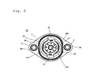
Fig. 2 is a bottom view of an example of the thermostat
device according to the present invention.
8
CA 03206301 2023- 7- 27
Fig. 3 is a partial cross-sectional view of an example
of the thermostat device according to the present invention,
illustrating a state where the thermostat device is attached
to a counterpart member.
Fig. 4 is a plan view illustrating the shape of a seal
member of the thermostat device in a natural length state
according to the present invention.
Fig. 5 is a partial cross-sectional view of a
conventional thermostat device.
Fig. 6 is a bottom view of the thermostat shown in Fig.
5.
Fig. 7 is a bottom view of another conventional
thermostat device.
Description of Embodiment
[0015]
An embodiment of a thermostat device according to the
present invention will be described based on the drawings
below. The thermostat device 10 according to the embodiments
shown in Figs. 1 to 3 is used in a coolant system of an
engine, for example. Specifically, the thermostat device 10
is disposed at an inlet or outlet side of a coolant path
connecting a radiator with the engine and controls the
temperature of the coolant circulating through the engine by
9
CA 03206301 2023- 7- 27
opening and closing the coolant path depending on the
temperature of the coolant.
[0016]
The thermostat device 10 includes a hollow housing 1
forming a flow path L leading to the cooling path inside, as
shown in Fig. 3, a thermo-element 17 one end of which is
disposed in the housing 1, a valve body 15 formed on the
outer periphery of the thermo-element opening and closing
the flow path L, a coil spring 16 as a biasing member biasing
the valve body 15 in the closing direction, and a frame 19
holding one end of the coil spring 16. For the convenience
of description, the upper and lower sides of the thermostat
device shown in Fig. 3 are simply referred to as "the upper"
and "the lower."
[0017]
In the present embodiment, the housing 1 is made of
synthetic resin. The housing 1 is provided with a body 20
with a capped nearly-cylinder shape at whose lower end an
opening 20c is formed, a pair of legs 21, 21 standing up
from the opening edge of the body 20 and extending downward
facing each other, a connecting port 23 of the radiator side
formed at the top of the body 20, and a pair of flanges 2,
2 protruding outward from the lower outer periphery of the
body 20.
CA 03206301 2023- 7- 27
The housing 1 is attached to the counterpart member 4
with the legs 21 inserted in mounting holes 5 of the
counterpart member 4. An engine-side connecting port 40 and
a bypass-side connecting port 41 are formed on the
counterpart member 4. The flow path L in the housing 1
communicates the radiator-side connecting port 23 and the
engine-side connecting port 40 via mounting hole 5.
As
described above, the flow path L leads to a coolant path
connecting the engine and the radiator and constitutes part
of the cooling path.
Meanwhile, the bypass-side connecting port 41
communicates with the engine-side connecting port 40 through
the mounting hole 5, and the communicating portion
constitutes part of a bypass path that circulates the coolant,
not passing the radiator, through the engine.
For example, when the thermostat device 10 is disposed
to the inlet side of the engine of a vehicle, the thermostat
device 10 is attached to the water pump that supplies the
coolant to the engine. In this case, the member of the water
pump to which the thermostat device is attached is the
counterpart member. It is to be noted that the thermostat
device, needless to say, may be disposed at the outlet side
of the engine of a vehicle.
[0018]
11
CA 03206301 2023- 7- 27
As shown in Fig. 2, a bolt hole 2a is respectively
formed on the pair of flanges 2, 2. Metal sleeves (without
reference sign) are press-inserted into the bolt holes 2a,
and bolts (not shown) are inserted therethrough for mounting
the thermostat device 10 to the counterpart member 4. An
annular groove 24 is formed at the lower edge of the opening
located inside the bolt holes 2a of the body 20 so as to
surround the opening 20c, and a seal member 25 is attached
to the annular groove 24. The seal member 25 seals between
the housing 1 and the counterpart member 4 and prevents the
coolant flowing in the housing 1 and the mounting hole 5
from leaking outside, with the thermostat device 10 being
attached to the counterpart member 4.
The inside (interior area) of the seal member 25 on
the body 20 defines the inside of the housing 1. An annular
valve seat 20b is formed on the inner periphery just above
the lower end opening edge of the body 20 located inside the
housing 1. The flow path L is opened and closed by the valve
body 15 unseated from and seated on the valve seat 20b.
[0019]
The upper end of the thermo-element 17 is inserted into
the inside of the housing 1.
The thermo-element 17 is
disposed to align with the axial line at the axis of the
body 20. The thermo-element 17 includes an element case 30
12
CA 03206301 2023- 7- 27
inside which thermal expansion material such as wax is
enclosed, and a piston 3 is inserted into the element case
30 retractably.
When the temperature of the coolant surrounding the
element case 30 rises and the thermally expanding material
inside is warmed to expand, the piston 3 exits from the
element case 30, and the thermo-element 17 extends. On the
contrary, when the temperature of the coolant surrounding
the element case 30 goes down and the thermally expanding
material inside is cooled to contract, the piston 3 enters
the element case 30, and the thermo-element 17 contracts.
Thus, the thermo-element 17 acts extending and contracting
operations depending on the temperature of the coolant.
The tip end of the piston 3 located at the upper end
of the thermo-element 17 fits with the cylindrical-shaped
boss 20a formed at the inside top portion of the body 20.
Thus the upward translation of the piston 3 against the
housing is blocked. The extending and contracting operation
causes the element case 30 to move upward and downward
without changing the position of the piston 3 against the
housing 1.
[0020]
The valve body 15 is fixed on the outer periphery of
the element case 30, whereby the valve body 15 moves up and
13
CA 03206301 2023- 7- 27
down with the element case 30 accompanying the extending and
contracting motion of the thermo-element 17. When the valve
body 15 moves downward due to the extension of the thermo-
element 17, the communication of the flow path L is allowed
because the coolant can flow through the space made by the
unseating of the valve body 15 from the valve seat 20b. On
the contrary, when the valve body 15 moves upward and seats
on the valve seat 20b due to the contraction of the thermo-
element 17, the communication of the flow path L is blocked.
Thus the valve body 15 opens and closes the flow path L in
this manner.
[0021]
The upper end of the coil spring 16 is in contact with
the backside of the valve body 15. The coil spring 16 is
disposed to surround the periphery of the thermo-element 17.
The lower end (one end) of the coil spring 16 is held by the
frame 19.
[0022]
The frame 19 is hooked at the tip end portion of the
pair of legs 21, 21 formed in the housing 1 and prevented
from moving downward against the housing 1. A penetrating
hole 19a is formed at the center of the frame 19.
The
element case 30 can freely upward and downward go through
the penetrating hole 19a. That is, the element case 30 is
14
CA 03206301 2023- 7- 27
movable up and downward against the frame 19.
[0023]
The coil spring 16 is a compressive spring and is
disposed between the valve body 15 and the frame 19 in a
compressed state. Thus, the valve body 15 is biased upward
(to the valve seat 20a) by the coil spring 16.
In this
configuration, when the temperature of the coolant around
the thermo-element 17 rises high and the thermo-element 17
extends, the valve body 15 moves downward against the biasing
force of the coil spring 16 and is unseated from the valve
seat 20b. Meanwhile, when the temperature of the coolant
around the thermo-element 17 becomes low and the thermo-
element 17 extends, the valve body 15 moves upward by the
biasing force of the coil spring 16 to approach the valve
seat 20b.
[0024]
As shown in Fig. 2, an annular groove 24 formed on the
housing 1 is rounded rectangular and has a vertically-long
shape in the present embodiment. A pair of flanges 2, 2 are
provided so as to protrude outward from the longitudinal
side of the annular groove 24. As described above, bolt
holes 2a are formed on each of the pair of flanges 2, 2.
Thus the pair of bolt holes 2a, 2a are disposed as to sandwich
the annular groove 24 from both sides of the short direction
CA 03206301 2023- 7- 27
of the annular groove 24.
The pair of legs 21, 21 are
disposed inside the annular groove 24 and on the position
corresponding to both ends of the longitudinal direction of
the annular groove 24.
[0025]
A seal member 25 to be fitted to the annular groove 24
is made of an elastic material such as rubber and is circular
in shape in the state of natural length, as shown in Fig. 4.
The state in which the seal member 25 is at its natural
length (natural length state) refers to the state in which
the seal member 25 is not compressed or elongated and no
load is applied to the seal member 25, which can also be
described as the cavity shape of the mold that forms the
seal member 25. The seal member 25 is perfectly circular in
shape if the seal member 25 is perfectly circular in plan
view when viewed as a whole. For example, protrusions may
be formed on the inner or outer circumference of the seal
member 25, arranged in the circumferential direction.
The circumferential length (circumferential length) of
the seal member 25 is the same as the circumferential length
(circumferential length) of the annular groove 25.
[0026]
As described above, the thermostat device 10 according
to the present invention includes a housing 1 attached to
16
CA 03206301 2023- 7- 27
the mounting hole 5 of the counterpart member 6 and having
a flow path L for the coolant formed inside, the seal member
25 between the counterpart member 4 and the housing 5 in a
liquid-tight manner, the thermo-element 17 whose one end is
formed inside the housing 1, performing expanding and
contracting operations depending on the temperature of the
coolant, the valve body 15 that opens and closes the flow
path L by the expanding and contracting operations of the
thermo-element 17, and the coil spring 16 (a biasing member)
biasing the valve body 15 in the closing direction.
A
deformed annular groove 24 is formed in the housing 1 to
which the seal member 25 is fitted, and the seal member 25
is perfectly circular in shape in a state of natural length.
[0027]
In the above configuration, since the annular groove
24 is deformed and not perfectly circular in shape, portions
are formed having a narrower width and a wider width of a
straight line direction passing through the center of the
annular groove 24. This configuration makes it possible to
shorten the fastening pitch (distance between the bolt holes
2a) by providing the flanges 2 on both sides of the narrow
width portion and forming the bolt holes 2a in the flanges,
thereby reducing the size of the housing 1, which in turn
enlargement of the size of the thermostat device 10 can be
17
CA 03206301 2023- 7- 27
inhibited. [0028]
The shape of the seal member 25, before being fitted
in the annular groove 24, is perfectly circular in a state
of natural length as shown in a plan view in Fig. 4. The
circumference of the seal member 25 in natural length 2nr (r
is the radius of the seal member 25 in the perfect circular
shape) is equivalent to the circumference of the annular
groove 24. Since the seal member 25 is made of rubber, for
example, and is elastic, the seal member 25 can be fitted
into the annular groove 24 by deforming to fit the shape of
the annular groove even if the shape of the seal member is
different from that of the annular groove 24.
[0029]
Thus, even if the annular groove 24 is not a perfect
circle, by forming the shape of the seal member 25 to be a
perfect circle before fitting it into the annular groove 24,
the seal member 25 becomes not directional. As a result,
the conventional positioning protrusions 71a (Fig. 7) are no
longer necessary, and the seal member 25 can be fitted into
the annular groove 24 from any position, thus improving the
assemblability of the seal member 25.
Further, a seal member 25 having a perfectly circular
shape in a state of natural length can be fitted into an
annular groove having a different shape from that of the
18
CA 03206301 2023- 7- 27
annular groove 24 shown in Fig. 2 if the annular groove has
the same circumference equal to 2nr of the circumference of
the seal member 25. This eliminates the need to prepare the
seal members 25 of different shapes for different types of
the thermostat devices 10, and reduces the number of
dedicated parts, thereby improving the versatility of the
seal members 25 and reducing costs.
[0030]
In the portions of wider width in the straight line
direction passing through the center of the annular groove
24, the interior space of the housing 1 can be bulged in the
same direction to form a bulge. When the bulge is disposed
to face the connecting port 40 of the engine side, the
pressure loss of the coolant passing through the housing 1
can be reduced. In contrast, when the bulge is disposed to
the opposite side of the connecting port 40 of the engine
side, in the case the thermostat 10 is disposed at the inlet
side of the engine, the mixing is appropriately performed of
the low-temperature coolant passing through the radiator
flowing in from the connecting port 23 of the radiator side
and the high-temperature coolant not passing through the
radiator flowing in from the connecting port 41 of the bypass
side.
[0031]
19
CA 03206301 2023- 7- 27
The annular groove 24 is rounded-rectangular in shape
in the thermostat device 10 according to the present
embodiment. When the annular groove 24 is formed vertically
long as above, the fastening pitch can be easily shortened
and the thermostat device 10 can be miniaturized by providing
the bolt holes 2a on both sides in the short-length direction
of the annular groove 24. Further, by forming the annular
groove 24 in a rounded rectangular shape, the annular groove
24 becomes a relatively simple shape having fewer changing
curvature parts even though not perfectly circular, so that
the seal member 25 is easily fitted even in the case the
seal member 25 having the perfectly circular shape in the
natural length state is fitted to a deformed annular groove
24.
[0032]
The thermostat device 10 according to the present
embodiment is provided with a frame 19 that supports one end
of the coil spring (a biasing member) 16.
Further, the
housing 1 includes a hollow body 20 having an opening 20c at
one end thereof, in which one end of the thermo-element 17
is inserted, and a pair of legs 21, 21 standing up at the
opened edge of the body 20 and supporting the frame 19 at
the tip end portion thereof. The pair of legs 21, 21 are
located inside the annular groove 24 on both sides of the
CA 03206301 2023- 7- 27
longitudinal direction end of the annular groove 24, whereby
the legs 21 are easily disposed with shortening the fastening
pitch.
[0033]
However, the arrangement of the legs is not limited to
the above and can be changed adequately. Further, the number
of legs is not limited to a pair (two) and, for example,
more than three legs may be provided with an equal space
along the circumferential direction of the valve seat 20b.
The one end of the coil spring (the biasing member) 16 may
be supported by the counterpart member 4 by eliminating the
legs 21.
Further, the shape of the annular groove 24 is not
limited to rounded rectangular and may be deformed shapes.
For example, the annular groove may be elliptic and, in this
case, equivalent effects can be obtained compared to the
case where the annular groove is rounded rectangular. As
described above, the deformed shape means a shape other than
a perfect circle, and includes polygons, rounded polygons,
circles having a partially cut part, teardrop shapes, etc.,
in addition to rounded rectangles and ellipses.
The number of flanges 2 and bolt holes 2a can be
changed appropriately, not limited to those shown in drawings.
[0034]
21
CA 03206301 2023- 7- 27
The preferable embodiment of the present invention is
described in detail above; modifications, transformations,
and alterations are possible as far as not departing from
the scope of the claims.
List of Reference Signs
[0035]
1 Housing
2 flange
2a bolt hole
3 piston
4 counterpart member
5 mounting hole
10 thermostat device
15 valve body
16 coil spring (biasing member)
19 frame
20 body
20a boss
20b valve seat
21 legs
24 annular groove
25 seal member
L flow path
22
CA 03206301 2023- 7- 27