Note : Les descriptions sont présentées dans la langue officielle dans laquelle elles ont été soumises.
WO 2022/232097
PCT/US2022/026279
COVER FOR TRAY WITH CONTAINERS
CROSS-REFERENCE TO RELATED APPLICATION
[0001]
This application claims the benefit of each of U.S. Provisional Patent
Application No.
63/180,242, filed on April 27, 2021, and U.S. Provisional Patent Application
No. 63/301,594, filed on
January 21, 2022.
INCORPORATION BY REFERENCE
[0002]
The disclosures of each of U.S. Provisional Patent Application No.
63/180,242, filed on April
27, 2021, U.S. Provisional Patent Application No. 63/301,594, filed on January
21, 2022, and U.S.
Design Patent Application No. 29/821,528, filed on December 30, 2021, are
hereby incorporated by
reference for all purposes as if presented herein in their entireties.
BACKGROUND OF THE DISCLOSURE
[0003]
The present disclosure generally relates to covers for trays that hold,
display, and/or transport
containers.
SUMMARY OF THE DISCLOSURE
[0004]
According to one aspect, the disclosure is generally directed to a cover
for at least partially
overlying a tray holding one or more containers, the cover comprising a
central panel, at least one end
flap foldably connected to the central panel, and at least one attachment flap
foldably connected to the
central panel, the at least one attachment flap includes a base portion and an
attachment portion
separably connected to the base portion, the attachment portion for being
attached to a portion of the
tray.
[0005]
According to another aspect, the disclosure is generally directed to a
blank for forming a cover
for at least partially overlying a tray holding one or more containers, the
blank comprising a central
panel, at least one end flap foldably connected to the central panel, and at
least one attachment flap
foldably connected to the central panel, the at least one attachment flap
includes a base portion and an
attachment portion separably connected to the base portion, the attachment
portion for being attached
to a portion of the tray when the cover is formed from the blank.
1
CA 03215797 2023- 10- 17
WO 2022/232097
PCT/US2022/026279
[0006]
According to another aspect, the disclosure is generally directed to a
method of forming a cover
for at least partially overlying a tray holding one or more containers
comprises obtaining a blank
comprising a central panel, at least one end flap foldably connected to the
central panel, and at least one
attachment flap foldably connected to the central panel, the at least one
attachment flap includes a base
portion and an attachment portion separably connected to the base portion, the
attachment portion for
being attached to a portion of the tray. The method further comprises folding
the at least one end flap,
and at least partially separating the at least one attachment flap from the
central panel such that the at
least one attachment flap is positioned for being attached to a portion of the
tray.
[0007]
According to another aspect, the disclosure is generally directed to a
package comprising a tray
holding one or more containers, and a cover at least partially overlying the
tray. The cover comprises
a central panel, at least one end flap foldably connected to the central
panel, and at least one attachment
flap foldably connected to the central panel, the at least one attachment flap
includes a base portion and
an attachment portion separably connected to the base portion, the attachment
portion attached to a
portion of the tray.
[0008]
Those skilled in the art will appreciate the above stated advantages and
other advantages and
benefits of various additional embodiments reading the following detailed
description of the
embodiments with reference to the below-listed drawing figures. It is within
the scope of the present
disclosure that the above-discussed aspects be provided both individually and
in various combinations.
BRIEF DESCRIPTION OF THE DRAWINGS
[0009]
According to common practice, the various features of the drawings
discussed below are not
necessarily drawn to scale. Dimensions of various features and elements in the
drawings may be
expanded or reduced to more clearly illustrate the embodiments of the
disclosure.
[0010]
Fig. 1 is a plan view of an outer surface of a blank for forming a cover
for a tray according to a
first exemplary embodiment of the disclosure.
[0011]
Fig. 2 is a perspective view of a cover formed from the blank of Fig. 1
above a tray holding a
plurality of containers according to the first exemplary embodiment of the
disclosure.
[0012]
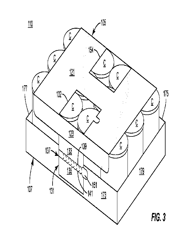
Fig. 3 is a perspective view of the cover and tray with containers of Fig.
2 attached to form a
package according to the first exemplary embodiment.
[0013]
Fig. 4 is a perspective view of the tray and containers of Fig. 3 with the
cover separated
therefrom.
2
CA 03215797 2023- 10- 17
WO 2022/232097
PCT/US2022/026279
[0014]
Fig. 5 is a plan view of an outer surface of a blank for forming a cover
for a tray according to a
second exemplary embodiment of the disclosure.
[0015]
Fig. 6 is a perspective view of a cover formed from the blank of Fig. 5
and attached to a tray
with containers to form a package according to the second exemplary
embodiment.
[0016]
Corresponding parts are designated by corresponding reference numbers
throughout the
drawings.
DETAILED DESCRIPTION OF THE EXEMPLARY EMBODIMENTS
[0017]
The present disclosure generally relates to covers for trays, packages,
constructs, sleeves,
cartons, or the like, for holding and displaying containers such as jars,
bottles, cans, etc. The containers
can be used for packaging food and beverage products, for example, beer, soft
drinks, soups, beans,
corn, vegetables, meat products, snack foods such as chips, nuts, candy, etc.
The containers can be
made from materials suitable in composition for packaging the particular food
or beverage item, and
the materials include, but are not limited to, glass; plastics such as PET,
LDPE, LLDPE, HDPE, PP,
PS, PVC, EVOH, and Nylon; and the like; aluminum and/or other metals;
composites such as
paperboard; or any combination thereof.
[0018]
Covers according to the present disclosure can accommodate containers of
numerous different
shapes. For the purpose of illustration and not for the purpose of limiting
the scope of the disclosure,
the following detailed description describes food or containers (e.g., lidded
paperboard or aluminum
containers) at least partially disposed within trays covered by the cover
embodiments. In this
specification, the terms "lower," "bottom," "upper," "top," "front," and
"back" indicate orientations
determined in relation to fully erected covers/trays/packages, etc.
[0019]
As described herein, covers may be formed by multiple overlapping panels,
end flaps, and/or
other portions of blanks. Such panels, end flaps, and/or other portions of the
blank can be designated
in relative terms to one another, e.g., "first", "second", "third", etc., in
sequential or non-sequential
reference, without departing from the disclosure.
[0020]
Fig. 1 shows a plan view of an exterior side 101 of a blank 103 used to
form a cover 105 for a
tray 107 (Fig. 2) or other construct in accordance with a first exemplary
embodiment of the disclosure.
The cover 105 can be sized to cover/overlie/engage a plurality of containers C
held in the tray 107. In
the illustrated embodiment, the containers can be snack food containers,
beverage cans, or could be any
other suitable type and size of container (e.g., e.g., beverage containers,
cartons, etc.) without departing
3
CA 03215797 2023- 10- 17
WO 2022/232097
PCT/US2022/026279
from the disclosure. The cover 105 can be provided together with a tray 107
and one or more containers
C as package 110 (Fig. 3).
[0021]
As shown in Fig. 1, the blank 103 has a longitudinal axis Li and a lateral
axis L2. The blank
103 includes at least one panel for engaging one or more containers of the
plurality of containers C. hi
the illustrated embodiment, the blank 103 can include a top panel or central
panel 121.
[0022]
The blank 103 can also include a plurality of end flaps foldably connected
to a respective panel
of the plurality of panels. In the illustrated embodiment, the blank 103 can
include a first side end flap
123 foldably connected to the central panel 121 at a lateral fold line 125,
and a second side end flap 127
foldably connected to the central panel 121 at a lateral fold line 129.
[0023]
A plurality of attachment flaps can be foldably connected to respective
panels of the plurality
of panels and/or end flaps of the plurality of end flaps of the blank 103. As
shown, a first attachment
flap 131 can be foldably connected to the central panel 121 and/or the first
side end flap 123 at a portion
of the lateral fold line 125. The first attachment flap 131 can include a base
portion 133 and a distal or
attachment portion 135. A tear strip 137 can be defined between a pair of
spaced apart lateral lines of
weakening or lateral tear lines 139, 141 (broadly, "first line of weakening"
and "second line of
weakening", respectively) such that the tear strip 137 is separably attached
to the base portion 133 of
the attachment flap 131 at the lateral tear line 139, and separably attached
to the attachment portion 135
at the lateral tear line 141. In this regard, the attachment portion 135 can
be separably attached to the
base portion 133 of the attachment flap 131 at one or both of the tear lines
139, 141.
[0024]
As also shown, the attachment flap 131 can be at least partially separable
from the central panel
121 at a pair of spaced longitudinal cuts 143, 145 that extend from the fold
line 125 to respective
endpoints of a lateral cut 147. A generally U-shaped or other at least
partially curved cut 149 can
interrupt the longitudinal tear line 145 to define a tab 151 of the tear strip
137 extending away from the
tear line 145.
[0025]
With continued reference to Fig. 1, a second attachment flap 153 can be
foldably attached to
the central panel 121 and/or the second side end flap 127 at a portion of the
lateral fold line 129. The
second attachment flap 153 can include a base portion 155 and a distal or
attachment portion 157
separably attached to the base portion 155 at a lateral line of weakening or
lateral tear line 159 (broadly,
"third line of weakening"). The attachment flap 153 can be at least partially
separable from the central
panel 121 at a pair of spaced longitudinal cuts 161, 163 that extend from the
fold line 129 to respective
endpoints of a lateral cut 165.
4
CA 03215797 2023- 10- 17
WO 2022/232097
PCT/US2022/026279
[0026]
In the illustrated embodiment, the attachment flaps 131, 153 are generally
aligned along a
longitudinal centerline CL1 defined along the central panel 121, and which is
generally parallel to the
longitudinal axis
[0027]
It will be understood that one or both of the attachment flaps 131, 153
and associated features
can have a different configuration without departing from the disclosure. For
example, in one
embodiment, the attachment flap 153 can be provided with a tear strip
similarly to the configuration of
the attachment flap 131 described above.
[0028]
The blank 103 can be provided with one or more applications of an
adhesive, such as glue. In
the illustrated embodiment, glue can be provided on the attachment portions
135, 157 of the respective
attachment flaps 131, 153 on the exterior surface 101 of the blank 103, and on
portions of the side end
flaps 123, 127 generally aligned with the respective attachment portion 135,
157 on an interior surface
of the blank 103. The glue described herein can be, for example, a hot melt
adhesive, a high tack glue,
an epoxy, a polymeric cement, etc., or combinations thereof.
[0029]
Referring additionally to Figs. 2 and 3, the cover 105 formed form the
blank 103 is shown
attached to the tray 107 with containers C according to the exemplary
embodiment of the disclosure.
[0030]
In the illustrated embodiment, the tray 107 can include a bottom/bottom
panel (not shown), a
pair of sidewalls/side panels 173, 175 extending upwardly from the bottom
panel, and a pair of end
walls/end panels 177, 179 extending upwardly from the bottom panel to define
an interior 181 of the
tray 107 in which the plurality of containers C are held/supported. Adjacent
sidewalls/side panels and
end walls/end panels of the tray 107 can be attached by associated structure,
e.g., corner webs,
attachment flaps, etc. It will be understood that they tray 107 can have a
different shape, size,
configuration, etc., without departing from the disclosure. It will be further
understood that a construct
different from the tray 107 can be provided for engagement with the cover 105
without departing from
the disclosure.
[0031]
As shown, the cover 105 can be formed and applied/attached/engaged with
the tray 107 by
positioning the central panel 121 over the tops of the respective containers
C, e.g., so as to be generally
parallel and spaced above the bottom panel 171 of the tray 107.
[0032]
The side end flaps 123, 127 can be folded downwardly relative to the
central panel 121 of the
blank 103/cover 105 at the respective fold lines 125, 129 so as to be
generally perpendicular to the
central panel 121 and so as to be generally parallel to the respective side
panels 173, 175 of the tray
107.
CA 03215797 2023- 10- 17
WO 2022/232097
PCT/US2022/026279
[0033]
Simultaneously or thereafter, the attachment flap 131 can be separated
from the central panel
121 at the respective cuts 143, 145, 147 and folded downwardly at the
respective portion of the fold
line 125. Such movement of the attachment flap 131 can cause a portion of the
base portion 133 to
overlap and adhere to the side end flap 123 with glue with the remainder of
the base portion 133, the
tear strip 137, and the attachment portion 135 extending downwardly therefrom.
[0034]
Similarly, the attachment flap 153 can be separated from the central panel
121 at the respective
cuts 161, 163, 165 and folded downwardly at the respective portion of the fold
line 129 such that a
portion of the base portion 155 is overlapped and adhered to the side end flap
127, with the attachment
portion 157 extending downwardly therefrom.
[0035]
As shown, the separation of the attachment flaps 131, 153 from the central
panel 121 can form
respective openings 132, 154 in the central panel 121, and which are also
aligned along the longitudinal
centerline CL1 of the central panel 121.
[0036]
In such an arrangement, the cover 105 can be lowered further toward the
tray 107 until the
attachment portions 135, 157 are at least partially aligned with the
respective side panels 173, 175 of
the tray. Thereafter, the attachment portions 135, 137 can be attached, e.g.,
adhered via glue, to the
respective side panels 173, 175 to attach the cover 105 to the tray 107.
[0037]
The aforementioned attachment of the cover 105 to the tray 107 can provide
an arrangement
such that a generally low clearance is provided between the tops of the
containers C supported by the
tray 107 and the central panel 121 of the cover 105. In this regard, the cover
105 can maintain the
position/arrangement, e.g., upright, packed, nested, etc., of the containers C
in the tray 105 for shipping,
transport, storage etc.
[0038]
In one embodiment, a user engagement feature 167 is defmed in the central
panel 121 between
the openings 132, 154 when the attachment flaps 131, 153 are separated from
the central panel 121.
The user engagement feature 167 can have the configuration of a handle or
other grasping structure for
grasping, lifting, carrying, or otherwise manipulating the combined cover
105/tray 107.
[0039]
When it is desired to detach/uncouple the cover 105 from the tray 107,
e.g., at a retail location
or point of sale, in one embodiment, an operator can engage the tear strip 137
of the attachment flap
131, e.g., by grasping the tab 151, and pulling the tear strip 137 to separate
from the base portion 133
and the attachment portion 135 of the attachment flap 131 at the tear lines
139, 141. In such an
arrangement, the attachment portion 135 of the attachment flap 131 can remain
attached/adhered to the
side panel 173 of the tray 107, and the remainder of the cover 105 can be free
to move at least partially
6
CA 03215797 2023- 10- 17
WO 2022/232097
PCT/US2022/026279
away therefrom. For example, in one embodiment, the side end flap 123, the
base portion 133 of the
attachment flap 131, and the central panel 121 of the cover 105 can be at
least partially moved/flipped
over the tops of the containers C in the tray 107 so as to expose the
containers C for unpacking.
[0040]
As best shown in Fig. 4, the cover 105 can be further/fully removed from
the tray 107 by
separating the base portion 155 of the attachment flap 153 from the attachment
portion 157 at the tear
line 159. In such an arrangement, the central panel 121, side end flaps 123,
127 and base portions 133,
155 of the respective attachment flaps 131, 153 can be fully removed/separated
from the tray 107, with
the attachment portions 135, 157 remaining attached thereto. Such
disengagement of the cover 105
from the tray 107 can facilitate removal of the containers C from the tray
107, and/or can expose the
containers C and the tray 107 for presentation as a retail item.
[0041]
In view of the foregoing, the cover 105 can be configured/adapted for
attachment to a tray 107
or other construct for holding containers C, which can be provided together as
a package 110. The
cover 105 can include attachment features to facilitate attachment of the
cover 105 to the tray 107, such
as one or more portions of the respective flaps 131, 153 and the side end
flaps 123, 143. The cover 105
can also include one or more separation features to facilitate separation of
the cover 105 from the tray
107, such as one or more of the tear strip 137, tear lines 139, 141, and tear
line 159.
[0042]
Turning to Fig. 5, a blank for forming a cover 205 (Fig. 6) according to a
second exemplary
embodiment of the disclosure is generally designated 203. The blank 203 and
cover 205 can have one
or more features similar to those described above with regard to the blank 103
and cover 105, and like
are similar features are designated with like or similar reference numerals.
[0043]
As shown in Fig. 5, the blank 203 includes the has a longitudinal axis Li
and a lateral axis L2.
The blank 103 includes the top panel or central panel 121, the first side end
flap 123, the second side
end flap 127, and the attachment flaps 131, 153 and associated features.
However, the attachment flaps
131, 153 can be positioned laterally offset from one another and from the
longitudinal centerline CL1
of the central panel 121, as shown. In one embodiment, the attachment flaps
131, 153 can be spaced
apart from the longitudinal centerline CL1 of the central panel 121.
[0044]
In this regard, the attachment flaps 131, 153 can have a length in the
longitudinal direction that
is greater than that described above with regard to the attachment flaps 131,
153 of the blank 103/cover
105.
7
CA 03215797 2023- 10- 17
WO 2022/232097
PCT/US2022/026279
[0045]
With additional reference to Fig. 6, the cover 205 can be formed from the
blank 203 in a manner
similar to that described above with regard to the cover 105, with the
openings 132, 154 formed by the
separation of the central panel 121 offset from one another along the
longitudinal centerline CL1.
Furthermore, the openings 132, 154 can be positioned so as to intersect a
lateral centerline CL2 of the
central panel 121.
[0046]
The cover 205 can be attached/removed from the tray 107 in a manner
similar to that described
above with regard to the cover 105 to form a package 210. However, owing to
the generally longer
attachment flaps 131, 153 of the cover 205, the cover can be configured to
engage the tray 107 holding
containers C that are taller than those described above with regard to the
cover 105.
[0047]
It will be understood that one or more portions of the blank 103/cover 105
and/or the blank
203/cover 205 can have a different configuration, shape, arrangement, etc.,
without departing from the
disclosure.
[0048]
In general, the blank may be constructed from paperboard having a caliper
so that it is heavier
and more rigid than ordinary paper. The blank can also be constructed of other
materials, such as
cardboard, or any other material having properties suitable for enabling the
carrier to function at least
generally as described above. The blank can be coated with, for example, a
clay coating. The clay
coating may then be printed over with product, advertising, and other
information or images. The blanks
may then be coated with a varnish to protect information printed on the
blanks. The blanks may also
be coated with, for example, a moisture barrier layer, on either or both sides
of the blanks. The blanks
can also be laminated to or coated with one or more sheet-like materials at
selected panels or panel
sections.
[0049]
As described herein, a line of weakening can include one or more of tear
lines, cut lines, etc.
As an example, a tear line can include: a slit that extends partially into the
material along the desired
line of weakness, and/or a series of spaced apart slits that extend partially
into and/or completely through
the material along the desired line of weakness, or various combinations of
these features. As a more
specific example, one type tear line is in the form of a series of spaced
apart slits that extend completely
through the material, with adjacent slits being spaced apart slightly so that
a nick (e.g., a small somewhat
bridging-like piece of the material) is defined between the adjacent slits for
typically temporarily
connecting the material across the tear line. The nicks are broken during
tearing along the tear line.
The nicks typically are a relatively small percentage of the tear line, and
alternatively the nicks can be
omitted from or torn in a tear line such that the tear line is a continuous
cut line. That is, it is within the
scope of the present disclosure for each of the tear lines to be replaced with
a continuous slit, or the like.
8
CA 03215797 2023- 10- 17
WO 2022/232097
PCT/US2022/026279
For example, a cut line can be a continuous slit or could be wider than a slit
without departing from the
present disclosure.
[0050]
In accordance with the exemplary embodiments, a fold line can be any
substantially linear,
although not necessarily straight, form of weakening that facilitates folding
therealong. More
specifically, but not for the purpose of narrowing the scope of the present
disclosure, fold lines include:
a score line, such as lines formed with a blunt scoring knife, or the like,
which creates a crushed or
depressed portion in the material along the desired line of weakness; a cut
that extends partially into a
material along the desired line of weakness, and/or a series of cuts that
extend partially into and/or
completely through the material along the desired line of weakness; and
various combinations of these
features. In situations where cutting is used to create a fold line, typically
the cutting will not be overly
extensive in a manner that might cause a reasonable user to incorrectly
consider the fold line to be a
tear line.
[0051]
The above embodiments may be described as having one or more panels
adhered together by
glue during erection of the carrier embodiments. The term "glue" is intended
to encompass all manner
of adhesives commonly used to secure carrier panels in place.
[0052]
The foregoing description of the disclosure illustrates and describes
various exemplary
embodiments. Various additions, modifications, changes, etc., could be made to
the exemplary
embodiments without departing from the spirit and scope of the disclosure. It
is intended that all matter
contained in the above description or shown in the accompanying drawings shall
be interpreted as
illustrative and not in a limiting sense. Additionally, the disclosure shows
and describes only selected
embodiments of the disclosure, but the disclosure is capable of use in various
other combinations,
modifications, and environments and is capable of changes or modifications
within the scope of the
inventive concept as expressed herein, commensurate with the above teachings,
and/or within the skill
or knowledge of the relevant art. Furthermore, certain features and
characteristics of each embodiment
may be selectively interchanged and applied to other illustrated and non-
illustrated embodiments of the
disclosure.
9
CA 03215797 2023- 10- 17