Note: Descriptions are shown in the official language in which they were submitted.
~6~
Method of_and aJ~aratus for thickenincl red muds derived
from bauxiteL and similar slurries
This invention relates to the thickening of muds
having clay-sized particles and yield pseudo-plastic
properties produced by industrial processes and, more
particularly, although not exclusively, to the thiek-
S ening of red muds produced during the production of
alumina frotn bauxite.
The most economical way of obtaining alumina from
bauxite ore involves the Bayer process. This utllizes
the reactions of solid aluminum hydroxide (Al(O~1)3) and
aluminum oxide trihydrate and monohydrate (Al2O3.3H2O
and Al2O3.M2O) with a~ueous caustic soda to form soluble
sodium aluminate. The soluble compound is separated Erom
insoluble impurities, precipitated as alumina trihydrate
and calcinecl to form commereial grades o~ alumina.
'rhe insoluble impurities o~ the ore remaininc~ ater
t.he caustic soda treatment are known as "red mucls" and
these are thoroughly washed ko remove solubl.e prodlJcts
beEore being di.scarded. The washing is normally carried
out in a counter-current manner in several stages. Each
.stage involves mixing the mud slurry underflow ~rom an
earlier stac3e with the clarified overflow from a later
stage. Ater each washing step, a flocculant is added to
the mixture and the resulting mud flocs are allowed to
'~'
~z~
settle and thicken in a clarifier/thickener vessel. The
thickened mud is drawn off from the bottom of the vessel
and passed to the next stage and the clarified overflow
is injected as wash liquor in the previous stage. The
washing normally takes place in a feedwell or feed pipe
before the mixture is discharged into the thickener/
clarifier~ It is usual to stack several shallow thickener/
clari~ier vessels in a vertical manner to save space and
operating costs. Nevertheless, the capital costs and
space requirements of such a washing and thickening pro-
cedure are substantial because of the large surface area
requirements of such thickener/clarifier vessels. One
way of reducing such capital costs would be to enhance
the ability of each thickener/clarieier to thicken the
mud because the efficierlcy of the washing procedure is
increased as the solids content of the mud from each
stage is increased. The mud removecd as underflow from a
conventional thickener/clarifier has a solids content of
15 to 30%. The use of synthetic flocculants instead of
the traditional starch has recently improved this Eigure
to 17-33'~, but this improvement is not sufficient to alter
significantly the econornics of the washing procedure.
The use of deep thickeners (as discussed by Dr. J.
L~ Chandler in an article entitled "Development of the
Deep Thickener" produced by the Technical Development
Department oE Alcarl Jamaica Company in ,January 1~0)
instead of conventional shallow thickener/clarieiers
of large sur~ace area improves the thickening eEeect,
but a deposit o~ inactive (i.e. thlck and irnrnobile) mud
builds up at the periphery Oe the vessel. rrhis build
up of inactive rnud is undesirable because it re~uces the
active volume Oe the vessel available eor settliny and
thickening and because the inactive mud tends to slump
downwards periodically and block the mud outlet, or it
may build up towards the level of the liquid surface,
thus impairing the clarity of the overflow. Atternpts to
~2~
use conventional ra~ing mechanisms to clear the entire
inner volume of the vessel to preven~ inactive mud build
up have proven costly and impractical in view of the high
torque requirements of the conventional mechanisms when
used in this way.
Moreover, while deep thickeners are capable of
increasing the solids content of the mud outflow, the
natural thickening rate of the mud flocs is fairly slow
and improvements could be obtained if this rate could
lo be increased.
An object of the present invention is to provide a
method o~ and apparatus for overcoming the above dis-
advantages of deep thickener vessels while maximizing
their ability to thicken the muds.
According to one aspect of the invention there is
provided a method of thickening a slurry of red mud
derived from bauxite ore or other pseudoplastic mud-like
slurry having clay-sized particles, comprising: mixing
said slurry with washing liquor and a flocculating agent;
passing the mixture into a deep thickener vessel having a
substantially cylindrical side wall, at least one under-
flow outlet at the bottom for removal of thickened slurry
and at least one overflow outlet at or adjacent to the
top for removal of clarified liquor; stirring said slurry
above said at least one underflow outlet with a stirrer
having a rotational profile that decreases in width from
top to bottom and which comprises substantially vertical
rod-like members to enhance dewatering of the slurry;
allowing a body of thick inactive slurry to build up
around said cylindrical side wall; and operating said
stirrer to maintain a central volume of fluid active
slurry in communication with said at least one underflow
outlet while causing the stirrer to contac-t a surface of
said body of inactive slurry to cause said body to resist
slumping of the inactive mud into said at least one
underflow outlet.
- 3a -
According to another aspect of the invention there
is provided apparatus for thickening a slurry of red mud
derived from bauxite or other pseudoplastic mud--like
slurry having clay-sized particles, which comprises:
a deep thickener vessel having a substantially cylin
drical side wall, at least one underflow outlet at the
bottom for removal of thickened slurry and at least one
overflow outlet at or near the top for removal of a
clarified liquor; means for introducing a mixture of said
slurry, washing liquor and a flocculating agent into the
vessel at the top; and a stirrer having a rotational
profile that decreases in width from top to bottom and
which comprises substantially vertical rod-like members
located above said at least one underflow outlet for
enhancing the dewatering of the slurry; said stirrer
being sized and positioned such that, upon rotation, the
stirrer allows a body of thick inactive slurry to build
up around said cylindrical wall while maintaining a
central volume of fluid active slurry in communication
with said at least one underflow outlet, and such that a
surface of said body of inactive slurry is contacted by
said stirrer to cause said body to resist slumping into
said at least one underflow outlet.
4~3~
Some of the terms used in this description re~uire
explanation, as follows.
The ter~ "rod-like member" is intended to mean a mem-
ber which is narrow and elongated. The member may have a
circular cross-section but this is not essential. Mowever,
if the cross-section is non-circular, the member should
usually not be plate-lilce, i.e., considerably larger in
width than in thickness. The important consideratio
is that the member should be capable o~ moving through
a mud-like slurry in a direction at right angles to its
long axis without causing significant movements of the
slurry body or currents within the slurry body. The
member may be stiff but can be flexible if supported
at both ends.
By " inactive mud" we mean a slurry that has achieved
a high solids content such that it no longer readily flows
in a fluid manner. Such mud has pseudo-plastic yield pro-
perties and is not readily pumpable.
By "active mud" we mean a slurry which is capable of
flowin~ in a fluid manner.
By the "profile" of inactive mud we mean the shape at
the edge of a layer of such mud when the layer is viewed
in vertical cross section. The profile is determined by
the angle of repose of the mud. The proEile of a mud
layer laid down in the absence oE stirring or raking
is referred to as the "natural proeile". ~t should be
appreciated that when a thickener is being operated the
pro~ile may vary to some extent with time and it may not
be a fixed line but rather a band over which the solids
concentration rapidly varies.
By the term "deep thickener" we mean a thickener
vessel having a su~ficient depth that the thickening of
the slurry is substantia:Lly increased at the lower levels
of the slurry body by virtue of the weight of slurry in
~64~
the intermediate and upper levels. Generally this means
that the ratio o~ the height above the underflow outlet
of the interface between the slurry layer and an overlyin~
layer of clarified liquor to the diameter of the vessel is
approximately at least O.S to 1.
sy using a stirrer comprising substantially vertical
rod-like members in a deep thickener vessel it is possible
not only to improve the degree oE thickening which takes
place but also to maintain a large active volume within
the vessel and generally to prevent blockage of the under-
flow outlet. Moreover, these benefits can be obtained
without the stirrer having a high torque demand since
the rod-like members move easily through the slurry.
The substantially vertical rod-like members enable
dewatering of the slurry to take place rapidly because
they create vertical channels in the flocculated solids
through which the water may pass freely towards the sur-
face. Furthermore, by using the stirrer to prevent the
inactive mud from adopting its natural profile and posi-
tion in the vessel, the problems of slumping and undue
inactive mucl build up can be avoided.
It is not necessary to stir the entire volume of the
slurry with;n the vessel. The solids content of the slurry
increases as the bottom of the vessel is approached, so de-
watering of the slurry (i.e. the thickening of the slurry
flocs by expulsion of water therebetween) becofnes progress-
ively more dieicult towards the bottom of the vessel.
A substantiaL lmprovement in the clewatering efEect can
thus be achieved ie only the bottom slurry layers (e.g.
the bottoln third oE the slurry voluMe) is stirred with
the ~ub.stantially vertical rod-like members. ~lowever,
stirring at any vertical level improves the dewatering
effect to some extent and the stirrer may operate over
the entire vertical height oE the slurry body, if desired.
In the horizontal direction, the stirrer may extend
from the centre of the vessel to the peripheral wall at
~286~
-- 6 --
all vertical levels, but this is not preferred. It is
much better to shape the stirrer in such a manner that
its rotational profile (l.e. its maximum outline when
viewed horizontally) decreases in width from top to bot-
tom. That is, at the top (near the slurry/clarifiedliquor interface) the stirrer may extend to (or near to)
the vessel wall, and at the bottom (above the under~low
outlet), the stirrer may only project horizontally by a
short distance beyond its central axi.s.
Advantageously, the rotational pro~ile of the stirrer
is generally triangular (decreasing in width from top to
bottom) with a straight or concave side edge. That is,
if a straight line is visualized between the periphery of
the rotational profile at the top and the periphery of the
rotational profile at the bottom, no intermediate part
of the profile should extend horizontally beyond this
line. If the side edge of the rotational profile is
convex, it is Eound that the torque demand of the stirrer
significantly increases whereas there is little or no
further increase in the volume of active mud or further
decrease in the risk of slumping, etc~
It is even more advantageous if the rotational pro-
file is rnade to correspond approx.imately in shape to the
natural profile of the inactive mud layer, while being
positioned closer to the vessel wall than the natural
proeile. r~he inactive mud, when deposited in the absence
of stirring, generally adopts the shape o~ an inverted
bell cllrve. 'l'hat .is, the intermediate parts of the pro-
Eile s].ope inwardly in an approximately straight line, but
the top flares outwardly and the bot~om curves inwardly.
~hen the rotational profile of the stirrer is given a
similar .shape, it projects int.o the inactive mud layer
to the same extent at each vertical level, so the torque
demands of the stirrer at each level are the same and the
overall torque demand is minimized. In actuality, since
the inactive mud becomes more compact towards the bottom,
~Z1~il6~
7 --
an equal torque distribution will only be obtained i~ the
bottom parts of the stirrer project less deeply into the
inactive mud than the top parts. This can be achieved
by making the slope of the central part of the rotational
profile slightly less than (e.g. up to 10 and preferably
up to 5 less than) the slope of the central part o~ the
natural profile. Thus, for example, if the slope of the
natural profile varies from 60 to 70, the slope of the
rotational profile can be set at 60.
It should be appreciated that when speaking o~ the
stirrer projecting into the inactive mud body this may
not in fact be the case in practice. If the stirrer is
operated before the inactive mud layer builds up, the
stirrer may never project significantly into the inactive
mud because it prevents the inactive mud from building
up beyond the rotational profile of the stirrer. What we
really mean in such a case is that the stirrer projects
into the volume between the actual profile of the inactive
mud and its natural profile, i.e. its shape and location
adopted in the absence of stirring.
rChe width and positioning of the stirrer at the bottom
are important to some extent. If the width is increased,
the active volume of the mud will be increased and the
inactive mu~ will be less likely to bui]d up to the out-
let Eor c]arified liquor. ~lowever, the torque demand
increases as the width increases, so a width must be
chosen which gives suitable advantages without undue
torque. The bottom Oe the ~tirrer is usually located
above the underElow outLet in the vessel bottom. 'Che
separation between the vessel bottom and the stirrer
should be selected so that inactive mud cannot build up
sueEiciently to reach khe outLet. This depends to some
extent on the width of the stirrer at the bottom and the
angle oE repose of the mud.
The stirrer may be rotated quite slowly because
adequate dewatering takes place at low speeds and the
~86~
-- 8
torque demand increases as the speed is increased. At
really fast speeds of rotation, the body of the slurry
may be caused to rotate in the thickener vessel. This
is undesicable because the thickening effect i5 then re-
duced. The optimum speed depends to some extent on the
diameter of the vessel, the number of rod-like members,
etc. but generally it can be stated that none of the rod
like members of a stirrer should exceed a rotational speed
of about 15 to 20 feet per minute. This corresponds to
one rotation every eight minutes for a thickener of the
usual size.
The rod-like members may be supported by arms ex-
tending horizontally from a central vertical rotatable
shaft. The arms may be provided at two or more vertical
levels and there may be two or more (e.g. 2, 3 or 4)
arms at each level. When more arms are provided, slower
rotational speeds may be employed and an improved de-
watering effect can be achieved, but the torque demand
increases as the nwnber of arms and rod-like members
increase. Most preferably, two arms are provided at
each of three levels and 3 to 10 rod-like members are
connected to each arm.
The rod-like members are made substantially vertical
to provide vertical channel~ Eor dewatering, but the rods
may be angled from the vertical to a smalL extent, iE
desired. For example, the rods may be angled radially
outwardly or in tht~ direction Oe rotation by up to about
45, preferably by up to 30.
While the thickener vessel is normally providec~ with
one central. urlderfLow outlet eor the thickened mud, more
than one outlet may be providecl, or example to reduce
the possibility Oe blockage. When there is more than
one outlet, they should preferably be grouped around the
centre of the bottom wall and the bottom of the stirrer
should be large enough to maintain all Oe the outlets
free Oe inactive mud.
36~
g
The invention is capable of producing thickened
slurries having a solids content much higher (e.g. a~
least 50% higher) than those aehievable with conven-
tional shallow thiekening vessels. Depending on the
type of mud-like slurry, the achievable solids content
may fall within the rangè of at leas~ 30 to 50% by weight.
Preferred embodiments of the present invention, are
described in detail below with reference to the accom-
panying drawings, in which:
Figure 1 is a cross-section of a thickener vessel
which is not provided with a stirrer and thus shows the
natural profile of the body of inactive mud;
Figure 2 is a cross-section similar to Fig. 1 show-
ing a thickener vessel provided with a stirrer;
lS Figure 3 is a top plan view of the stirrer shown in
Fig~ 2;
Figures 4 is a schematic view of a system or
controlling the level of a mud/liquor interface in
the thickener;
Figure 5 is a schematic view of a system Eor re-
circulating clarified overflow to the slurry input;
Figures 6 and 7 are graphs showing the efects of
the percentage solids in the feed to the vessel on the
settling rates of the slurry; and
Figs. ~, 9 and 10 are graphs showing the results of
settling tests carried out using flocculant.s under various
conditions.
Fig. I. f~how3 a vertical cross-sectlon oE a deep
thicl~erler lO operatecl without a stLrrer.
When mud slurry, washLng liquor and 10cculant are
introduced into the thickener lO through a feed well
l~, the mud Eloes settle to Eorm an active mud volume
13 ancl clarifiecl washing :liquor 14 separated by a mud/
liquor interEace ll. The thickened mud is withdrawn
rom an underflow outlet 15 and the clarified washing
~2136~8~
- 10
liquor overflows a~ an outlet 16. Gradually a body 17
of inactive (i.e. thick and relatively immobile) mud
builds up around the periphery of the thickener vessel
and extends (when viewed in vertical cross-section)
in an inverted bell curve from the under~low outlet
15 upwards and outwards to the peripheral wall of the
thickener at the interface 11. The profile of the in-
active mud layer is determined by the angle of repose
of the mud and will vary to some extent according to
the type of mud and other conditions.
A problem with this type oE thickener is, as noted
above, that the thick inactive mud may slump towards
the outlet 15 from time to time and may thus restrict or
even block the outlet. Moreover, the upper ends of the
15~ body 17 of inactive mud may extend beyond the mud-liquor
interface ll and reduce the clarity o the liquor ex-
iting the outlet 16. This arrangement also encourages
"rat-holing", i.e. the tendency of the active mud 13
to compress and thiclcen excessively except for narrow
vertical channels which receive loost of the liquid
throughput. Rat-holing causes the solids content oE
the mud flowing from outflow 15 to decline dramatically~
An uncontrolled build up of inactive mud ~urthermore
reduces the residence time oE the active mud in the
thickener and conse~uently lowers the percentage solids
at the outlet~
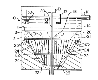
A pre~erred apparatus according to the invention is
shown in Fiy. 2. The thickener vessel lO is basLcally
the same as the vess.el oE r'i(J. 1 and identical part~s are
identiEiecl by the same refererlce nwneral.s. rrhe apparatus
of Fig. 2 has a stirrer 1~ operated by a motor lg. The
stirrer consists o~ a centr~l vertical rod 20 having a
nulnber of radially-extending arlns 21, 22 and 23 rigidly
attache~l thereto. The arMs are provided at three hori-
æontal levels with arms 21 being uppermost, arms 22 being
648~
-- 11 --
intermediate and arms 23 being lowermost. At each verti-
cal level, there are preferably at least two and possibly
three or four such arms.
Vertical~ or substantially vertical, rod-like elements
24 (which may be cables, rods, wires or the like) extend
between the arms. The rod-li1~e elements act as stirring
and dewatering means and the arms 21, 22 and 23 prin-
cipally act as supports for the rod-like elements but
inevitably do themselves provide some stirring.
Upon rotation of the stirrer 18, the rod-like elements
24 have three effects. Firstly, by creating disturbances
in their wake, they form channels in the flocculated solids
(active mud) which allow egress of water to the surface.
Secondly, in consequence of the rotational profile of the
stirrer as shown in Fig. 2, the outermost rod-like ele-
ments prevent the volume of inactive mud from increasing
to assume the natural profile ~6 and position as shown
in Fig. 1 (and in broken lines in Fig. 2) by continuously
preventing the deposition of new inactive mud on the
outermost inactive mud surface, and also prevent the mud
from slumping to the outlet. Thirdly, the constant
stirring of the active mud maintains its fluidity and
prevents rat-holing.
As well as being provided with the rod-like elements
24, the upper arms 21 are provided at thelr outerlnost
ends with plate-lilce paddles 25 (shown more clearly in
Fig. 3) extending downwaedLy and inclined relative to
the direction oE rotation to deelect inactive mud located
adjacent to the vessel periphery towarcls the centre o~
rotation. The uaddles are provided to positively ensure
that the inactive mud level does not rise above the arm
21 and thus jeopardise the clarity of the ]iquor 14.
By comparing Figs. 1 and 2 it will be seen that the
rotational profile of the stirrer 18 (i.e. its radially
outermost periphery as shown in Fig. 2) is similar to
the natural profile 26 of the inactive mud 17, but it is
~2~
- 12 ~
located closer to the vessel wall and is inclined less
steeply. This rotational profile is achieved by mal~ing
uppermost arms 21 quite ]ong, by making intermediate arms
22 shorter and by making lowermost arms 23 quite shor~.
Moreover, while most of the rod-like members 24 are ver-
tical, the outermost ones are sloping as shown.
Between the arms 21, 22 and 23, the mud body 17 adopts
a sLoping profile which is again dictated by the angle of
repose of the mud.
The result of the above arrangement is that the torque
demand of the stirrer is kept to a minimum while the active
mud volume 13 in the thickener is kept high, slumping oE
the inactive mud layer is prevented and the solids in the
active mud compress and thicken uniformly as they move
from the mud-liquor interface 11 to the underflow outlet
15. The solids content of the mud exiting the outlet
15 remains fairly constant and high and there is little
tendency for the outlet to become blocked.
If the apparatus has to be shut down temporarily for
any reason, the rotation oE the stirrer 18 prevents the
central volume of active mud from settling and thicken-
ing unduly and keeps the outlet lS ~ree of large solid
particle.s.
To maintain low cost, the rod-like elements 2~ rnay be
of circular cross-section. ~lowever, any cross-sectional
shape can be employed which preEerably tends to cause the
slurry to Elow smoothly around the forward part of the
element but creates turhulence at the rearward part. For
example, the rods may be bulLet-shaped or triangular ~with
the apex foremost) in cross-section.
While the device shown has arms 21, 22 and 23 at three
difEerent vertical Levels, the nature Oe the stirrer may
be changed according to the height ~o diameter ratio of
the vessel and the available torque of the motor 19 etc.
The minimum number of arms is generally two in order to
~z~
- 13 -
provide the required support for the elements 24. ~ow-
ever, the greater the number o~ arms, the better the
rotational profile of the stirrer can be made to fit
the natural profile, but the larger are the torque
requirements.
If the vessel shown in Fig. 2 has a diameter of
forty feet and a height of 35 feet, preferably two to
four lowermost arms are provided 3 to 6 feet above the
outlet 15. These arms preferably extend 2 to 6 feet be-
yond the natural profile 26. There are preferably 2 to4 uppermost arms 21 extending within 1 to 2 feet o~ the
vessel wall to project 2 to 6 feet past the proEile 26 at
their level. The uppermost arms are preferably located
4 to 10 feet below the mud-liquor interface 11. There
are preferably 2 to 4 intermediate arms 22 located ap~
proximately mid way between the bottom and the top arms.
These arms project 2 to 4 feet beyond the natural profile
26.
The number of elements 24 is not limited. Normally
there are 3 to 10 elements per arm depending on the length
Oe the arm. The elements are secured by any suitable
means such as by drilling holes in the arms and securing
the ends of the elements in the holes.
In order to achieve the maximum thickening effect,
the mud/liquor interEace 11 should be kept as high in the
vessel as possible without unduly increasing the solids
content Oe ~he clarified over~low erom the outlet 16.
The thickeninc~ eEect takes place, at least partially, as
a result Oe the compressioll oE ~he mud elocs towards the
bottom of the apparatus due to the weight oE mud layers
thereabove. Thus, the greatest compression is achieved
when the inter~ace 11 is at its maximum heic~ht. In order
to keep the intereace at the required level it is neces-
sary to provide means for detecting the position oE the
interEace and means actuated by the detector means for
controlling the intereace level.
~2~
- 14 -
The means for detecting the level oE the inter~ace
can be of any suitable form, but it should preferably be
able to function even when the interface is ill-deEined.
Normally, the mud-liquor interface is well defined and
horizontal across the vessel. In the case of bauxite
red mud, ~he solids content of the solution changes at
the interface ~rom nearly clear liquor to 20% or more in
a matter of inches, but with other slurriès or in adverse
conditions, the interface may not be so well defined. I'he
detector means found to be the most reliable is a verti-
cally movable ultrasonic probe which locates the interfaceby sensing the density of t'ne slurry between its trans-
mission and receiving faces. A detector of this type is
indicated by the reference numeral 30 in Fig. 2.
The position of the interface 11 can be controlled by
varying the amount of slurry passing through the outlet
15. By increasing the rate of flow, the level of the
interface 11 can be caused to fall and, conversely, by
decreasing the rate of flow the level can be caused to
rise (assuming that the rates of introduction of the
slurry, wash liquor and flocculant into the vessel are
held constant). ~referably, means are provided which
automatically adjust the rate o~ flow through the out-
Jet 15 in accordance with the signals received from the
detector 30.
To achieve good operation it has been found that
a cascade type control l.oop is required to maintain a
Eixed or manually-set intereace level. ~Such a control
loop is indicated sch~matically in Fi9. ~. The ]etector
30 transmits a ~igna] to a controller 31 indicating tlle
position of the interEace ll. T~e controller 31 compares
the signal to that corresponcling to a desired level. If a
diEEerence in signals is detected, the controller 31 sends
a signal to a urther comparator 32 which compares it with
a signal from a flow meter 35. The comparator 32 sends a
signal to a speed controller 33 of a variable speed pump
~Z~48~
- 15 ~
34 until the signal from the flow meter matches the signal
from comparator 31.
This "cascade" control has been found to be the most
effective method of controlling the interface and detect-
ing underflow blockages quickly. Calibration of theflo~meter 35 is not important in the operation o~ this
loop.
As an alternative, the variable speed pump 34 can be
controlled directly by signals from the detector but it
has been found that smooth response is often dif~icult
to achieve and wide fluctuations may be caused in the
underflow rate through outlet 15 which can cause large
fluctuations in the percentage solids of the thickened
slurry.
Another factor which has proved to be of importance in
the operation of such thickeners, at least for bauxite red
muds, is the percentage solids content of the slurry in-
troduced into the thickener. This solids content is, for
bauxite mud/ conventionally 10 to 15~ by weight because
this is the percentage range ohtained by mixing the mud
underflow from a previous stage with the clarified liquor
~rom a later stage. Although it might be expected that
an increased solids output could be obtained by increasing
the solids input, we have determined that the thickening
operation can be made more ee~icient by reducing the solids
content of the input slurry to within the range o~ 2 to
by weight ~nd, more preferably 2 to ~ by weight. Within
this range, the tnud s]urry floccu].ates and settles much
more ef~iciently than at higher solids contents.
~o reduce the solids content o~ ~he input slurryr
clari~ied liquor 1~ exiting the thickener 10 (e.g. via
the outlet 16) can be recirculated by a purnp to the
s1urry input pipe in order to dilute the slurry.
suitable arrangement is shown in Fig. 5.
Fig. 5 shows a pipe 60 for carrying thickened tnud
from a previous stage and a pipe 61 for carrying clarified
~z~
- 16 -
liquor from a later stage. The mud and the liquor meet
and mix at the point where pipes 60 and 61 join together
and consequently washing takes place at this point. The
resulting slurry mixture then enters pipe 62 which conveys
it to the feed well 12 of the thickener 10. Before the
slurry enters the feed well, however, it is mixed with
addi~ional cl~rieied liquor taken from the thickener 10
via outlet 16, pipe 63, pump 64 and pipe 65 which joins
pipe 62. A flocculant is also mixed with the slurry
(after the dilution step) via pipe 66. Preferably, the
pipe 62 has a constriction (not shown) downstream of the
pipe 66 to slow the slurry flow and to allow the Eloccu-
lation to take place in a reasonably placid zone.
Only a small amount Oe clarified liquor is recirculated
in this way and most passes directly to the next stage via
the extension 67 of outlet 16.
Although, as stated above, the clarified liquor Eor re-
circulation can be taken from the feed through the outlet
16, the liquor may be taken directly from the thickener by
an alternative outlet iE desired, e.g. iE it is considered
important not to disturb the feed through the outlet 16.
The feed well 12 is designed to allow the flocculated
slurry to be introduced gently into the thickener, i.e. it
eliminates currents which may stir up the settling solids.
The feedwell is merely a cylindrical vessel having a cen-
tral lower opening located below the slurry surface. The
slurry Eeed is eed into the feed well in a tangential
manner adjacent to its inner wall so that currents flow
horizontally around the Eeed well rather than vertically
through the central hole.
Figs. 6 and 7 are ~raphs showin~ that the ran~e of
solids of 2 to 8 percent eor the input slurry is the
most desirable Eor Vauclreuil red muds. Fig. 6 shows
the settling rate versus the feeds solid percent (on a
logarithmic scale). When a flocculant is employed it
can be seen that the settling rate increases when the
il6~
- 17 -
solids content is between about 0.2 and 8 pereent. The
graph also shows (as a broken line) the upward flow of
liquor. It is only when the settling rate is to the right
of this line that positive settling takes plaee to give an
effeetive settling rate. This effeetive settling rate is
shown in Fig. 7 anci it can be seen that solids contents
between 2 and 8 pereent, and preferably 2 to 4%, give good
effeetive settling rates.
The nature of the flocculant employed also affects
the performance of the thickener.
The objective of flocculation is to produce large
dense flocs of mud which will settle quickly and dewater
readily once settled. Polyacrylamide sodium-polyacrylate
based flocculants provide good settling, compaction and
clarity, but these results depend to some extent on an-
ionicity, molecular weight, flocculant preparation, mixing
with mud, coneentration of the mud and conditioning time
for floc growth.
With regard to anionicity and molecular weight, over
the range of soda values found in mud wash eireuits, it
is found that more than one floeculant should be employed
to maximize the percent solids by weight in the underflow,
especially when the soda concentration drops below about
30 to 40 gpl total soda (as Na2C03). It is Eound tllat
diEeerent flocculants are effective over different ~anges
of tokal titratable socla (T.T.S.).
Figures ~, 9 and L0 illustrate the results of ]ab-
oratory tests employirlg various floeeulants in a pilot
thiclcener using bauxite red mud. rrhe narrow rang~ of
soda values over which ;om~ lloeeulants are eEEicient
should be note-l.
Fig. 3 shows the eompaction percentage solids versus
the flocculant anionicity of polyaerylarnide sodium poly-
aerylate fLocculants at various concentratiorls oE total
titratable soda. It can be seen that over these ranges
of total titratable soda, the floceulant anionicity should
36~
- 18 -
preferably be in the range of 40 to 90%, preferably 60 to
80~.
Fig. 9 shows the compaction percentage solids versus
the concentration of total titratable soda using a Eloc-
culant sold under the trade mark PRAE~TOL 2237 (60~
anionicity). This indicates that the flocculant is
effective in the range of up to 50 gpl T.T.S.
Fig. 10 shows the compaction (percentage solids) versus
concentration of T.T.S. errlploying a flocculant sold under
the trade mark ALCLAR WG-23 (77% anionicity). This indi-
cates that the 10cculant is eEfective in the range of lO
to 60 gpl T.T.S.
The mixing oE the flocculant solution with the mud
slurry should be done very quickly and thoroughly after
which a relatively short conditioning time appears to be
re~uired for the flocs to form to their maximum diameter
under gentle agitation. The degree of agitation should be
such as not to prevent their full growth nor harsh enough
to break down the fragile flocs beEore they reach the feed
well. Preferably, additional flocculant is added at the
feed well to offset the breakdown that occurs in the Eeed
piping following the initial formation of the flocs ater
mixing.
It has been found that the conventional multi-level
shallow thickener/cl~rifiers commonly used eor mud wash-
ing circuits can easily be converte3 into deep thiclceners
elnbodying the present invention. This can be done by
removing the hori~ontal dividers to eorrn a deep vessel
and rnoc3iEyin~ the conventional r~kes (which are normally
connected to a single central vertical rod) to Eorm a
stirrer as descriL)ed ~bove.
Althougtl the invention has been described in detail
with particular reference to the thickening of red muds
produced during the Bayer process, the invention can also
be applied to many rnud-like slurries having clay-sized
particles and yield pseudo-plastic properties produced
6~
-- 19 --
in the course of industrial processes (e.g. muds produced
during phosphate mining and treatment), provided such muds
are capable of undergoing flocculation. Variations may
be required in certain details, e.g. the percentages of
solids in the feed stream, the amounts of flocculan~s,
etc., but it is believed that these variations can readily
be determined by trial and simple experimentation~
It will be apparent to persons skilled in the art
that variations and modifications can be made to the
embodiments described above. All such variations and
modifications form part of this invention to the extent
they fall within the scope of the following claims.