Note: Descriptions are shown in the official language in which they were submitted.
129~739
BACK-MIRROR FITTED WITH ILLUMINATION LUGHT AT CAR SIDE
FILED OF THE INVENTION
-
The present invention relates to a rear view mirror for automobiles
and, in particular, to a rear view mirror provided with an illumination
light, charaterized in that the illumination light is mounted to be rotated
in all directions so that dark sides of the car may be easily illuminated.
In conventional vehicles there is no problem in driving forward
and backward during the night with the aid of head lights and rear lamps
mounted at the front and rear ends of the car. However, the sighting
of objects approaching from the dark right or left sides of the vehicle
or from above or below the vehicle is very difficult due to the enveloping
darkness.
Especially at night, backward driving or approach driving to other
cars or walls as well as driving into a garage or parking space is very
troublesome because of the darkness in the side directions. As a result,
safe driving is greatly hindered.
In order to solve the above-mentioned problems, the present invention
provides rotatable illumination lights for illuminating the dark side and
dark areas around the car by mounting tl3e light in the rear view mirror
case.
SUMMARY OF THE INVENTION
According to the present invention, a rear view mirror and light
assembly for vehicles is provided comprising a parallelepiped housing
adapted for mounting on the vehicle. A mirror is mounted on an exterior
wall of the housing, and a lamp mounted within a recess on an adjacent
Wall. The lamp is journalled between the forked end of a hollow shaft
for rotation about a first axis extending between the ends of the fork
while the hollow shaft is journalled in the housing for rotation about
a second axis extending perpendicularly thereto along the center of said
12917~9
shaft. The shaft and the lamp are separately driven by power means
located in the housing to selectively rotate the lamp about the first
axis and the forked end about the second axis, wherby the lamp is
universally adjustable.
Thus, the rear view mirror assembly is mounted on car in such a
way that the lamp may be rotated in all directions concurrently with the
adjustment of the mirror. In this way, dark areas may be optionally and
selectively illuminated. Consequently, safe driving at night can be
achieved because circumferential areas about the vehicle can be easily
seen even when the car is driven backward or driven to approach other cars
as well as for garaging.
Furthermore, circumferential areas about the car may be seen by a
driver's direct eyesight as well as by the indirect sighting of the driver
from his seat throught the mirrors.
The invention will now be described by way of example with reference
to the annexed drawings.
BRIEF DESCRIPTION OF THE DRAWINGS
Fig. 1 is a perspective view of a rear view mirror case provided
with openings for an illumination light and steering rod according to the
invention, including an exploded view of bhe base plate, steering rod, and
steering tube, to be mounted in the case :
Fig. 2 provides exploded perspec~ive views of a pillar and a mechanism
for the apparatus of the present invention in which :
Fig. 2a is a perspective view of the steering mecllanism which
operates the illumination light in all directions and also steers the mirror
in the up and down directions,
Fig. 2b is a perspective view of the base plate and the steering tuhe
encased together in the mirror case, and
- 2 -
1739
Fig. 2c is a right side view of a pillar, showing a retainer for
receiving a steering base plate,
Fig. 3 provides perspective views of internal structure of the
mechanism n which :
Fig. 3a is a perspective view of the interior of the mechansim,
showing members engaged with a driving shaft and a shaft tube,
Fig. 3b is an enlarged vertical section of worms and helical gears,
and
.~
Fig. 3c is an enlarged vertical section, showing the illumination
light being engaged with the driving shaft and shaft tube :
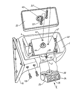
Fig. 4 provides exploded perspective views of the rear view mirror
and illumination light in which :
Fig. 4a i8 a perspective view of the back of the mirror, showing
drivin8 screws and a coupler"
., .
Fig. 4b is a plain perspective view of the mirror case in which the
mechanism case is fixed to the base plate by screws and the steering base
plate is fixed to the retainer by screws whereby the assembled mirror case
may be moved along the pillar, and
Fig. 4c shows an illumination light with a reflection member being
directed upwards, ready to be inserted in the illumination light insertion
opening :
Fig. 5 provides perspective views of the present invention in which
Fig. 5a is a plain perspective view, showing a reflection lamp of the
illumination light being driven upwards, and
1~91739
Fig. 5b is a plain perspective view, showing a reflection lamp
of the illumination light being driven downwards : and
Fig. 6 provides views showing the operation of the illumination
light in which :
Fig. 6a shows the illumination light being driven to the left,
and
Fig. 6b shows the illumination light being driven to the r.ght.
Legend
1. Back -mirror case
2. Illumination la~p tn8ertion opening
3. Steering rod insertion opening
4. H-shaped support bracket
7. Tubular steering collar
Stsering rod
11. Coil spring .
13. U-shaped ciip
14. Annular recess
19. Mechanism case
20. Illumination lamp
29. Tubular shaft
30. Support frame
31. Driving rod
32. Knurling member
33. Ratchet
40. Lid
41, 41' Holes
~`
-- 4 --
12~1739
nETAILED DESCRIPTION OF THE INVENTION
Referring to ~ig. 1 t the rear view mirror comprises a generally
parallelepiped case 1 having an opening 2 in its lower wall for the
insertion of an illuminating light L (Fig. 4) and an opening 3 at a
left lower edge for insertion of an adjustment or positioning mechanism
P(Fig. 2). An H-shaped support bracket 4 is mounted within the case
l. The hracket 4 is provi~ed with holes 5, 5' in each corner which
register with corresponding tubular posts 6, 6' provided in the case 1
and upon which the bracket 4 fixedly sits.
The adjustment mechanism P comprises a tubular steering collar 7
integral formed on the lower left arm of the H-shaped support bracket 4.
The collar 7 is adapted to slideably fit over a tubular rod 10 mounted
on a flat plate 15 which is exposed through the corner opening 3 in
the case 1,
The lower frontal e~ge of the collar 7 is provided with a plurality
of uniformly spaced slots 8 facing toward the plate 15 while a radially
inwardly directed shoulder 9 is formed on the interior of collar 7.
The tubular rod lO is provided with a plurality~of corresponding detents
or noses 8' and an arcuate shoulder 9' which causes the slots 8 and
nosss 8' to interer.gage and fit snuggly when the collar 7 and rod lU
are pushed axially together. In this condition the rod 10 extends
through and beyond the collar 7 over which is provided a collar
spring 11 held by a washer 12 and U-shaped clip 13 which fits onto an
annular recess.14 formed at the end of the rod 10.
- 5 -
1291739
As seen in Fig. 2 a flat plate 15 is intergrally attached at the
end of the rod 10 and is fixedly fit into a retainer 17 extending from and
integrally formed with a pillow block 16 which itself is adapted to be
mounted to the vehicle chassis or exterior member. The flat plate 15 is
secured to the retainer 17 by suitable screws 18 or similar fastening means
so that only the case 1 and its contents are moveable relative to the pillow
block 16.
As seen in Figs. 2 and 4, there is mounted on the support bracket 4
a case 19 in which the operating and adjustment mechanism for the mirror
are located. The case 19 is formed with upper and lower sections
adapted to be fastened together. The upper and lower sections of the case
l9 is provided with tubular shaft 29 at its corners, each having a hole
adapted to register with the tubular posts 6 so as to be secured to case
1 by suitable screws or bolts.
As seen in Fig. 3, there is located within the case 19 a mechanism for
driving the lamp 20 of the illuminating light L comprising motors 21 and 21'
and a mechanism for driving the mirrors M comprising motors 23 and 23'.
Each of thè motors 21 and 21' are provided with a correspo,ndin8 drive shaft
in the form of worms 24 wh;le each of the motors 23 and 23' are similarly
provided with drive worms 24'. The worms 24 engage with helical gears
25 and 25', which are respectively mounted on stub shafts 26 and 26' at
the ends of which are also carry driven gears 27 ~nd 27' which drive
further gears 28 and 28'.
The worm gear 28 is fixed to one end of a hollow tubular shaft 29,
the other end of which is forked, forming a U-shaped supporting frame 30
in which is retained the lamp 20. In this manner, the forked end is
rotatable about an axis passing through the center of the shaft 29. The
worm gear 28' is fixed on a driving rod 31 which passes through the tubular
shaft 29 and is formed with a knurled member 32 at its other end which
engages with a ratchet 33 in the housing for the lamp 20 so as to enable
rotation of the lamp about an axis perpendicular to that of the shaft 29,
as seen in Figs. 4 and 5.
_ 6 --
12~739
Inside the lamp 20 there is disposed a reflector 34 and a light
bulb 35. The electric wire 36 connected to both terminals of the lamp
20 is led outside via the insidehollow arms of the support frame 30.
Each of the two worms 24', coupled to the motors 23 and 23', driving
the mirror 22, operate driving screws 37 and 37', respectively, which are
loosely attached to the back of the mirror 22 so that by threading or
unthreading the s~rews 37 and/or 37' the mirror is tilted up or down
and sideways. The driving screws 37 and 37' pass through helical gears
38 and 38', respectively, which mesh with the worms 24'. Helical rings
39 and 39' meshing with the screws 37 and 37' are formed inside ~he
he~ical gears 38 and 38' and are aligned with holes 41 and 41' when the
lid 40 of the mechanism case 19 is put in place so that the screws 37 and
37' can pass therethrough.
When the screws 37 and 37' are passed through the holes 41 and 41'.
the lower ends of the driving screws 37 and 37' are tightened about
inside projections 42 and 42' of the helical rings 39 and 39'. As seen
in Fig. 4 a coupler 43 secured to the back of the mirror is placed over
an engagement ring 44 formed over the lid 40. Clamps 45 and 45' project
in tubular form from the back of the }id 40 and serve as support members
to keep the helical gears 38 and 38' from being lifted out of place.
Reference numerals 46 and 46' are lead wires cGnnecting each of the
motore 21, 21', 23, and 23' to convention vehicular power sources. The
motors 21 and 21' as well as motors 23 and 23' are preferably reversible
electrical motors and are connected to the power source through conventional
on-off andJor polarity reversing switches.
In practicej the present invention is used by fixing the pillow
block 16 to the side of the vehiole, preferably on the window frame just
as the conventional mirror is fixed.
To drive the lamp 20 in either the up or down direction the motor 21'
is actuated so that the associated worm 24 drives the helical gear 25'
which in turn drives the driving gear 27' of the shaft 26. since the
_ 7 _
1291~39
driven gear 28' meshes with the driving gear 27', the driving rod 31 is
rotated inside the tubular shaft 29. As a result the knurled member 32,
formed at the outer end of the rod 31, meshes with the ratchet 33, causing
the lamp 20 to rotate about the transverse axis between the arms of the
forked end, as indicated by the double arrow A.
Depending on the direction in which the motor 21' is driven, the lamp
20 will thus move up or down in t~le direction shown by the double arrow
A in Fig. 3 to enable the castirg of light in the up or down direction.
To rotate the lamp 20 about the axis of the tubular shaft 29 so as
to irradiate at front and rear acute angles as well as to the right orleft
side, the motor 21 is actuated, cau~ing the worm 24 to drive the helical
gear 25 which in turn drives the gear 27, whereby causing the tubular shaft
29 to rotate about its central axis. The rotation of shaft 29 causes
the forked support frame 30 to pivot to the ri8ht or left direction as
indicated by the arrow B, concurrently carrying with it the lamp 20, which
may be separately rotated about the perpendicular axis as indicated above.
The direction of rotation of the shaft 29 will also depend on the
direction in which the motor 21 is driven.
In addition to being able to radiate light in all directions of the
car by rotating the illumination lamp 20, the mirror is also constructed
so as to similarly function as now explained. The actuation of the motor
23' dri~es the helical gear 33' through the rotation of the worm 24' and
the associated driving screw 37', threadedly engaged around the inside
projection 42' of the helical ring 39', is pulled inwardly whereby mirror
22 is caused to pivot to the right to receive images of objects or places
illuminated by lamp 20 from that direction. To tilt the mirror 22 to the
left the ~otor 23 is actuated in the same manner, and the illuminated
objects from that direction will be observed. To release the driving
screws 37 and 37' from the inside projections 42 and 42' and to reset
the mirrors, forward-reverse mirrors switches (not shown) controlling the
motors 23 and 23' are actuated.
12!~1739
Thus, according to the present invention, all directions radiating
from the car may be illuminated by rotating the lamp 20 selectively in
any combination of directions. By using the lamp 20 of the present
invention, safe driving in the night, particularly in case of driving in
crowded places or garaging the car, can be achieved. The driver's
visibility may be particularly extended when the car is driven on curved
roads.
~ he present invention may also be used when changing tires at night,
coupling or uncoupling of chains in snow season, and in other repair works
of the car where illumination of the sides of the car are necessary.
~`
By fixing the pillow block 16 to the side window frame of the car,
location of the mirror case l may easily adjusted by manual operation,
since the steering base 15 and the retainer 17 being fixed together by
screws are resiliently held by the rod 10 pushed into the tube 7 which
is held by the resilient coil spring 11.