Note: Descriptions are shown in the official language in which they were submitted.
i35
Attorney Docket: P-us-sP-oo4s
ELECTRICAL POWER CIRCUIT FOR A VACUUM CLEANER
BACKGROUND OF THE INVENTION
1. Field of the Invention
The present invention relates generally to portable
5 vacuum cleaners, more particularly to, a vacuum cleaner capable
of operating with both air and liquid.
2. Description of Related Art
Currently, there exists portable vacuum cleaners which
pick up or vacuum solid or liquid material. These portable
10 vacuum cleaners are frequently referred to as "wet-dry" vacuum
cleaners. Commonly, such vacuum cleaners include an electric
motor for imparting rotation to a blower to create a partial
vacuum. The motor is typically connected by electrical wiring to
a plurality of batteries acting as the power source to power the
15 motor~ The vacuum cleaner also includes a switch which provides
for the coupling o~ electric power from the batteries to the
motor. Optionally, an accessory having a motor to drive a brush ~ -
or the like may be coupled to the vacuum cleaner.
One disadvantage of the above vacuum cleaner is that if
20 an accessory is attached, when the speed of the motor for the
vacuum cleaner is increased or decreased, the speed of the motor
for the accessory increased or decreased.
It is, therefore, an object of the present invention to
provide an electrical power circuit for a vacuum cleaner in which
fi~;
--2--
the speed of the motor for the vacuum cleaner may be increased or
decreased for changing the fan suction without affecting or
changing the speed of the accessory motor.
SUMMARY OF THE INVENTION
Accordingly, the present invention is a vacuum cleaner
and accessory attachment assembly including a vacuum cleaner and
an accessory attachment. The vacuum cleaner includes a motor, a
housing enclosing the motor and a fan driven by the motor for
producing a vacuum. The vacuum cleaner also includes a canister
removably attached to the housing for reception of air and
foreign matter into the canister in response to the vacuum
produced by the fan. The vacuum cleaner further includes a power
source and electrical wiring interconnecting the power source and
the motor. The accessory attachment is removably mounted to the
vacuum cleaner and includes a motor, and means for electrically
connecting the motor to the vacuum cleaner. The vacuum cleaner
includes mean~ for allowing the speed of the motor of the vacuum
cleaner to change while allowing the relative speed of the motor .
for the accessory attachment to remain constant.
One advantage of the present invention is thak the
electrical circuit provides power for changiny the rate of fan
suction by allowiny the speed of the motor for the vacuum cleaner
to be increased or decreased. Another advantage oE the present
invention is that the speed of the accessory motor remains
constant or is not increased or decreased when the speed of the
motor for the vacuum cleaner is increased or decreased.
Other advantages of the present invention will be
readily appreciated as the same becomes better understood by
reference to the following detailed description when considered
in connection with the accompanying drawings.
BRIEF DESCRIPTION OF THE DRAWINGS
Figure 1 is an elevational view with a portion broken
away o~ a vacuum cleaner incorporating the present invention.
Figure 2 is an elevational view of the vacuum cleaner
of Figure 1 and an accessory brush attachment in an assembled
condition.
Figure 3 is an exploded elevational view of the vacuum
cleaner and accessory brush attachment of Figure 2.
Figure 4 is a partial sectional view of the vacuum
cleaner and accessory brush attachment of Figure 2.
Figure 5 is an electrical circuit schematic of the
vacuum cleaner and accessory brush attachment of Figure 2.
Figure 6 is an alternate electrical circuit schematic
of the vacuum cleaner and accessory brush attachment.
DESCRIPTION OF THE PREFERRED EMBODIMENT
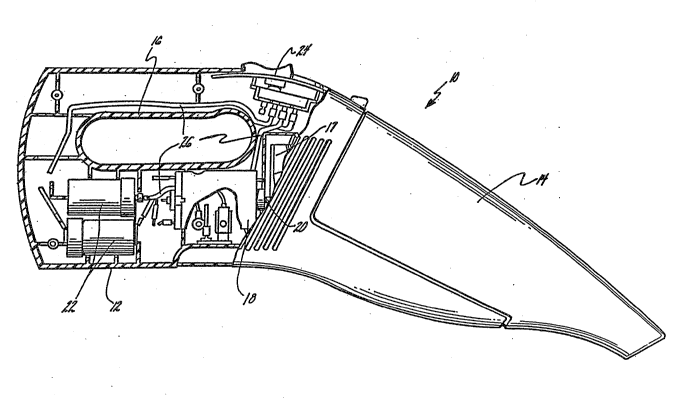
Referring to Figure 1, a vacuum cleaner 10
incorporating the present invention is shown. The vacuum cleaner
10 includes a central housing 12 having a canister 14 affixed to
a front end thereof and a handle 16 formed near the back end
thereof. The handle 16 is configured to be grasped by the hand
of a person using the vacuum cleaner 10 for the cleaning of
upholstery, rugsf as well as in the dusting of flat surfaces such
as the top o~ a l:able.
The housing 12 contains a source of suction or fan 17
which may also be referred to as a blower or impeller, and an
electric motor 18 coupled by a shaft 20 to the blower 17.
, .
~ 3~
Rotation of the shaft 20 by the motor 18 imparts rotation to the
blower 17 to create a partial vacuum and the accompanying suction
which draws air and foreign matter :into the canister 14. The
motor 18 is powered by a plurality of batteries 22. A
5 multi-position switch 24 is positioned on the upperside of the
handle 16 for convenient engagement by means of the thumb of a
person utilizing the vacuum cleaner 10. Operation of the switch
24 provides for the coupling o~ electric power from the batteries
l0 22 to the motor 1~ for activation of the motor 18. Electric
wiring 26 connects the batteries 22 by the switch 24 to the motor
18.
Referring to Figures 2 through 4, the accessory or
power brush attachment 27 for use with the vacuum cleaner 10 is
15 shown. The accessory brush attachment 27 includes an accessory
motor 28 and an accessory housing 29 enclosing the accessory
motor 28 as illustrated in Figure 4. The forward end of the
accessory housing 29 includes a bxush cavity 30 formed therein.
A brush 31 is rotatably mounted within the brush cavity 30 and is
20rotated by the accessory motor 28.
The accessory brush attachment 27 also includes a
passageway 32 formed within the accessory housing 29 which
fluidly communicates with the brush cavity 30 and the canister
14. Air flow caused by the vacuum produced by the fan 17 of the
25vacuum cleaner 10 travels from the brush cavity 30, through the
passageway 32, and into the canister 14 o~ the vacuum cleaner 10.
The accessory brush attachment 27 includes a pair o~
laterally spaced contact strips 33 at one end thereof. The
contact strips 33 are metallic and flexible. The contact strips
s
33 are connected by electrical wiring 26 to the accessory motor
28. The vacuum cleaner 10 also includes a terminal block 34
secured to the vacuum housing 12. As illustrated in Figure 4,
the terminal block 34 includes a pair of contacts 35 which are
5 connected by electrical wiring 26 to the switch 24 and batteries
22 to allow electrical power to flow to the accessory motor 2~
upon actuating the switch 24~ -
Referring to Figure 5, a schematic diagram of an
electrical circuit 36 is shown. In the electrical circuit 36,
10 preferably four (4) batteries 22 are used. The batteries 22 are
serially connected by metallic strips 37 to each other. A
positive end ~8 of the first battery 22 is connected to a
positive terminal 39 o~ the fan motor 18 and a positive terminal
15 40 of an accessory motor 28. A negative terminal 41 of the fan
~ motor 18 is connected to a second pin 42 of the switch 24. A
¦ negative terminal 44 of the accessory motor 28 is connected to a
seventh pin 46 of the switch 24. A negative end 48 of the third
battery 22 is conneGted to a third pin 50 of the switch 24. A
20 negative end 52 of a fourth battery 22 is connected to a sixth
pin 54 of the switch 24. A metallic strip 59 interconnects pins
56, 58 and 54. It should be appreciated khat the switch 24 has a
pair of longitudinally spaced ~eet (not shown) for bridging a
pair of opposed pin connections.
The switch 24 has an "OFF" or non-operable position
¦ which prevents the flow of electrical power from the batteries 22
¦ to the motors 18 and 28. The switch 24 also has an "ON" or first
¦ operable position for allowing the flow of electrical power from
the batteries 22 to the motors 18 and 28. The switch 24 further
-6-
has a 1'BURST" or second operable position to increase or decrease
the flow of electrical power from the batteries 22 to the fan
motor 18 without changing the relatlve el2ctrical power flow to
, the accessory motor 28. The positions of the switch 24 and the
5 bridge connections between the pins are tabulated as follows:
' SWITCH BRIDGE CONN~CTIONS BRIDGE CONNECTIONS
POSITION FOR PINS WITHOUT FOR PINS WITH
ACCESSORY MOTOR ACCESSORY MOTOR
OF SWITCH OF SWITCH
~ 10 OFF 501 54 50, 54
¦ ON 42, 50, 54 42, 46, 50, 54
BURST 42, 54, 56, 58 42, 46, 54, 56, 58
¦ In operation, when the switch 24 is in the "ON"
¦ position and the accessory motor 28 is not attached or part of
15 the electrical circuit 3 6, three of the batteries 22 of the
electrical circuit 36 are used to supply sufficient electrical
I power to operate the fan motor 18. Electrical power flows from
the positive end 38 of the first battery 22 and across the
terminals 39 and 41 o~ the fan motor 18 and pins 42, 50 and 54 to
20 the negative terminal 48 of the third battery 22.
When the accessory motor 28 is attached or part of the
electrical circuit 36 and the switch 24 is in the ON position,
all four batteries 22 are used to supply sufficient electrical
power to operate the fan motor 18 and accessory motor 28.
.
XO~3t~;3~5i
Electrical power flows from the positive end 38 of the first
battery 22 across the terminals 39 and 41 of the fan motor 18 and
terminals 40 and 44 of the accessory motor 28 to the switch 24.
The switch 24 makes a bridge connection between pins 42, 46, 50
5 and 54 to allow electrical power to flow to the negative terminal
52 of the fourth battery 22 to complete the circuit.
When additional suction is desired and the accessory
motor 28 is not attached to the circuit 36, the switch 24 is
moved to the "BURST" position to electrically connect all four
lO batteri2s 22 to the motor 18 by the switch 24 making bridge
connections between pins 42, 56, 58 and 54 to increase the speed
of the fan motor 18. Also, when the accessory motor 28 is
attached to the electrical circuit 36, the switch 24 is moved to
the "BURST" position making bridge connections between pins 42,
l5 46, 56, 58 and 54 to electrically connect all four batteries 22
to change the speed of the blower or fan motor 18 without
changing the relative speed to the accessory motor 28 which
re~uires electrical power from all four batteries to operate.
Referring to Figure 6, an alternate embodiment of the
20 electrical circuit 36 is shown at 136. Like parts have like
numerals increased by one hundred (100). In the circuit 136,
preferably Eive (5) batteries 122 are used. The negative
terminal 152 of the ~ourth battery 122 is connected by electrical
wiring 126 to the third pin 150 of the switch 124. The metallic
25 strip 159 interconnects pins 150, 154 and 158. A negative
terminal 160 o~ the fifth battery 122 is connected by electrical
wiring 1~6 .to the ~irst pin 156 of the switch 124. The positions
of the switch 124 and the bridge connections between the pins are
tabulated as follows:
.2~
SWITCH BRIDGE CONNECTIONS BRIDGE CONNECTIONS
POSITION FOR PINS WITHOUT FOR PINS WITH
ACCESSORY MOTOR ACCESSORY MOTOR
ATTACHED ATTACHED
5 OFF 150, 154 150, 154
ON 142, 150, 154 142, 146, 150, 154
BURST 142, 156, 158, 150 142, 146, 150, 156, 158
In operation, when the switch 124 is in the l'ON"
position and the accessory motor 128 is not attached or part of
10 the electrical circuit 136, four of the batteries 122 of the
electrical circuit 136 are used to supply sufficient electrical
power to operate the fan motor 118~ Electrical power flows from
the positive end 138 of the first battery 122 and across the
terminals 139 and 141 of the fan motor 118 and pins 142, 150 and
l5 154 to the negative terminal 152 of the fourth battery 122.
When the accessory motor 128 is attached or part of the
electrical circuit 136 and the switch 124 is in the ON position,
all four batteries 122 are used to supply sufficient electrical
power to operate the fan motor 118 and accessory motor 128.
20 Electrical power flows from the positive end 138 of the first
battery 122 across the terminals 139 and 141 of the fan motor 118
and terminals 140 and 144 o~ the accessory motor 128 to the
switch 124. The switch 124 makes a bridye connection between
pins 142, 146 and 150 to allow electrical power to flow to the
25 neqative terminal 152 o~ the fourth battery 122 to complete the
circuit.
~066;~'~
When additional suction is desired and the accessory
motor 128 is not attached to the circuit 136, the switch lZ4 is
moved to the ''BURST'I position to electrically connect all five
batteries 122 to the fan motor 118 by the switch 124 making
5 bridge connections between pins 142, 156, 158 and 150 to increase
the speed of the fan motor 118. Also, when the accessory motor
128 is attached to the electrical circuit 136, the switch 124 is
moved to the "BURST" position making bridge connections between
pins 142, 146, 150, 156, and 158 to electrically connect all five
l0 batteries 122 to increase or decrease the speed of the blower or
fan motor 118 without changing the relative speed to the
accessory motor 128 which requires electrical power from four
batteries 122 to operate.
The present invention has been described in an
15 illustrative manner. It is to be understood that the terminology
which has been used is intended to be in the nature of words of
description rather than of limitation.
Obviously, many modifications or variations of the
present invention are possible in light of the above teachings.
20 Therefore, within the scope of the appended claims, the present
invention may be practiced otherwise than as specifically
described.