Note: Descriptions are shown in the official language in which they were submitted.
2~J '~9 D~~
PRE-SLIT INJECTION SITE AND TAPERED CANNULA
Field of the Invention
The invention pertains to coupling systems usable to
transfer materials from one flow conduit to another.
More particularly, the invention pertains to two-part
coupling members with a first part including a pre-slit
septum and second part including a blunt cannula. The
pre-slit septum slidably receives the blunt cannula to
effect the coupling.
A
~~49~~3
Background of the Invention
Injection sites usable with pointed cannulae have long been
known. For example, such sites can be formed with a housing having a
fluid flow path therein. A septum is positioned in the housing closing
the fluid flow path.
One injection site usable with a piercing cannula is disclosed in
U.S. Patent No. 4,412,573 to Zbed entitled "Injection Site." The Zbed
patent is assigned to the assignee of the present invention.
The pointed cannula can be forced through the septum into fluid
flow communication with the flow path in the housing. Known injection
sites usable with a piercing cannula can be physically damaged by
repetitive piercing caused by the sharp cannula. This damage, known as
coring or laceration, can result in subsequent leakage. -
Due to problems associated with infectious agents, personnel
using such pointed cannulae do so with great care. Notwithstanding
careful and prudent practice, from time to time, accidents do occur and
individuals using such pointed cannulae jab themselves.
Injection sites usable with a blunt cannula are also known. For
-- example, U.S. Patent No. 4,197,848 issued to Garrett, et' al., entitled
"Closed Urinary Irrigation Site" and assigned to the assignee of the
present invention discloses one such injection site. That injection
site is a relatively low pressure device having a relatively thin,
molded, sealing member. The sealing member has an opening therethrough.
A blunt cannulae can be forced through the sealing member placing
the cannulae into fluid flow communication with a fluid flow pathway in
the injection site.
_2_
r
2~4~~~~
Injection sites of the type noted above usable with a blunt
cannula have the advantage that the blunt cannula will not pierce the
skin of a user. On the other hand, it is important that the pre-slit
injection site reseal with enough force that fluids do not ooze
therefrom and that airborne particulate matter, bacterial or viral
matter do not enter therethrough.
Hence, there continues to be a need for a pre-slit injection site
which can be used with a variety of solutions and over a range of fluid
pressures. Further, there continues to be a need for such a pre-slit
injection site which will reliably reseal even after many insertions of
the blunt cannula.
Such an i nj ecti on si to shoul d be abi a to recei ve a 1 arge number
of insertions of the cannula without displaying reseal failure. Such
an injection site should provide for improved alignment of the cannula
on insertion. Improved alignment will result in less chance of damage
to the injection site after repeated insertions of the cannula.
Preferably, the injection site " would also be usable with a pointed
cannula. Preferably, a pre-slit injection site usable with a blunt
cannula will provide a reasonable level of insertion force such that
health care personnel will readily be able to insert the blunt cannula,
yet the cannula will not easily fall from or drop out of contact with
the septum.
-3-
24494~~
summary of the Invention
In accordance with the invention, an easily wipeable injection
site usable with a blunt cannula is provided. The injection site
includes a housing which defines a fluid flow channel therethrough.
The housing has a first and a second end.
A flexible sealing member is carried by the housing for sealing
the first end. The sealing member has a resealable opening therein.
The sealing member also is formed with a curved exterior peripheral
surface such that the blunt cannula can be sealingly inserted through
the opening and placed in fluid flow communication with the flow path.
Further, the blunt cannula can be removed from the opening with a
sealing member then interacting with the housing so as to reseal the
opening.
The housing can also be farmed with the first end including an
annular channel underlying the sealing member. The sealing member is
subjected to radially directed forces by a tapered surface of the first
end of the housing. These forces tend to reseal the opening in the
sealing member.
The sealing member can be a cylindrically shaped rubber member.
The first end of the housing can include an interior tapered surface
for receiving the sealing member and for applying the radially directed
forces to the sealing member.
A retaining member carried by the first end of the housing can be
used to retain the sealing member within the housing. The retaining
member can be generally U-shaped. Alternately, the retaining member
can be formed as a coiled spring.
The retaining member applies axially directed forces to the
sealing member. In one embodiment of the invention, the retaining
-4-
2049~~~
r
member deflects the sealing member and forms a curved exterior
peripheral surface thereon. The curved exterior peripheral surface is
an easily wipeable surface.
The retaining member deflects or distorts the upper and lower
peripheral edges slightly as a result of applying axial forces
thereto. When the blunt cannula is inserted into the slit in the
sealing member, an annular interior peripheral region of the sealing
member deforms further and fills, at least in part, the annular channel.
Deformation of this annular peripheral region results in an
insertion force in a range of 2.0 pounds (.7564 kilograms) to 5.0
pounds (1.891 kilograms). Preferably, the insertion force will have a
value of the order of 2.0 pounds (.7564 kilograms).
I The resealable opening in the sealing member can extend entirely
through that member. Alternately, the resealable opening can extend
only partway therethrough. In this embodiment, the end of the blunt
cannula will be used to tear through the remainder of the sealing
member.
The sealing member can be formed in two parts. An exterior
cylindrical portion can be slit completely. An interior cylindrical
unslit portion can be provided to seat the site until the blunt cannula
is inserted therethrough the first time.
The interior surface of the first end can be formed with the
taper in a range on the order of 5 degrees to 20 degrees. Preferably,
the interior surface will have a taper on the order of 12 degrees.
Thi s tapered surface permi is the use of a cyl i ndri cal ly shaped seal i ng
member.
To provide for leak-free insertion, the length of the slit in the
sealing member must be less than one-half the circumference of the
cannula being inserted therethrough. Hence, the slit length may exceed
-5-
w
the diameter of the cannula being inserted. In addition, the slit
length must be great enough, given the elastic limit of the sealing
member, to prevent tearing during insertion.
Further, in accordance with the invention, a coupling system for
coupling first and second fluid flow members together is provided. The
coupling system includes an injection site which is affixed to the
first fluid flow member. The injection site includes a housing. The
housing has a fluid flow path therethrough.
A sealing member is carried by the housing. The sealing member
has a resealable opening therein.
An annular retaining member is carried by the housing and
cooperates with the housing to retain the sealing member therein.
Radially directed forces are applied to the sealing member by the
housing, thereby urging the opening into a resealed condition.
A blunt cannula, affixed to second fluid flow member, has a fluid
flow path therethrough. The cannula carries a locking member for
lockingly engaging the housing when the cannula extends through the
opening of the sealing member. When so positioned, the two fluid flow
members are placed into fluid flow communication.
The locking member can include a luer-type twist lock fitting.
Alternately, the locking member can include slidably engageable members
which are responsive to axial movement of the injection site and ,the
cannula toward one another.
In accordance with further aspects of this invention, the blunt
cannula may be provided with features that facilitate insertion into
the injection site, enhance fluid flow or dispersion, increase tug
resistance, and-reduce kickback.
In particular, one embodiment of the cannula includes a tube with
a plurality of elongate discharge slots adjacent the distal end. The
-6-
~~~9~J~3
fluid changes direction as it passes laterally through the slots and
out of the tube. The flow area of the slots exceeds the flow area
inside the tube. This slot structure enhances fluid flow and
inspersion characteristics. In addition, the slots decrease the
contact surface area on the tube exterior so as to facilitate insertion.
In a further modification, the cannula includes a lead post on
the tube distal end to guide the cannula through the slit in the
injection site.
In another cannula embodiment, the tube is generally cylindrical
and the fluid discharges directly from an open end of the tube. The
exterior surface of the tube is provided with grooves to reduce the
contact surface area.
In still another cannula embodiment, the tube has a cylindrical
porti on and a tapered di stal end portion whi ch are each about equal i n
length. The taper facilitates insertion, and the remaining cylindrical
portion reduced kickback.
In yet another embodiment, the cannula includes an annular barb
which functions to reduce kickback.
Other advantages of a blunt plastic cannula in accordance with
the invention, relative to conventional steel needles include a higher
fluid flow rate capacity and simpler one-piece plastic design.
'~
06-22-00 04:04pm From-SIM MCBURNEY 4165951163 T-662 P.02/02 F-246
Other aspects. ref this invention are as follows:
In accordance: with an aspect of the present invention in a blood
sampling system, a i~ampling site useable with a blunt cannula device
comprising:
tubing adapted to be connected at one end to the patient in fluid
communication with Glle patient's vascular system and at the other end to a
fluid supply;
a reservoir assembly connected in-line to said tubing k~etween the
patient end and the fluid supply end, comprising a flaw through reservoir
to housing defining an interior clhamber fat holding fluid, and a retractable
plunger 4isposed within the r~3servoir housing adapted to be slidably
retracted
within the interior ch~~mber to create negative pressure within the chamber
effective to draw fluid from th~s tubing into the chamber;
a sampling site connected in-line to the tubing vetween the patient end
and the reservoir as;~embly, the sampling site compri..ing a flow thmugh
sampling site housing having an inlet connected to th4 tubing leading to the
reservoir assembly and an outlet connected to the tuk~ing leading td tile
patient, thereby defining a fluid channel thetehetweer~, wherein retraction of
the reservoir plunge) draws blood from the patient into the fluid channel;
means defining an aCC~ss aperture in the sampling site housing in
communication with the fluid channel; and
flexible meari~5 carried by the sampling site hv~ising for sealing the
access aperture, the moans having a curved exterior peripheral surface and a
resealaple opening therein such that d blunt cannuia can be sealingly inserted
through the opening and placed in fluid flow commNn~cation with the channel
to enable blood sampling therefrom and such that thE- blunt CannNla can be
removed from the o~>ening wiith tile flexible means interacting with the
housing
so as to reseal the resealable opening.
An injection site usable with a blunt cannula d~:vice cxan'lprising-'
3o A housir<g haring a fluid passageway therein and means defining first
and second openings within aaid housing in communication with said
passageway;
7a
5~5 22/06/2000 16:00 ~416595t163 OreceiverJ
CA 02049063 2000-06-22
2~~9~53
flexible means carried by said housing for sealing said first
opening , said means having a resealable opening therein and a
curved exterior peripheral surface such that a blunt cannula can be
sealingly inserted through said resealable opening and placed in
fluid flow cortmunication with said passageway and such that the
blunt cannula can be removed therefrom with said flexible means
interacting with said housing so as to reseal said resealable
opening;
means defining a generally radially extending shoulder on the
exterior for said housing for locking engagement with one type of
blunt cannula device;
means defined on the exterior of said housing for threaded
engagement with another type of blunt cannula device;
grasping means circumscribing said housing to aid in grasping said
infection site while inserting or withdrawing a blunt cannula, said
grasping means being tapered substantially throughout its length;
and
visually perceptible identification means carried by said housing
to identify said infection site as being usable with a blunt cannula
device, said identification means comprising a colored ring
circumscribing said flexible means and being of a color different
from said housing.
An infection site usable with a blunt cannula device
comprising:
a housing having an inlet and outlet and defining a fluid
channel therebetween;
means defining an access aperture in communication with fluid
channel; and
-7b-
A
2~49~6~
flexible means carried by said housing for sealing said access
aperture, said means having a resealable opening therein and a
curved exteri or pert pheral surface such that a bl unt cannul a can be
sealingly inserted through said opening and placed in fluid flow
cortmunication with said channel and such that the blunt cannula can
be removed therefrom with said flexible means interacting with said
housing so as fio reseal said resealable opening.
A blunt-ended cannula device for use with a pre-slit
infection site, said cannula device comprising:
an elongated member with a fluid flow channel extending
generally axially therewithin and through a distal of said member;
said elbngated member being generally cylindrical along a
substantial portion of its length and terminating in a generally
tapered distal end portion having a blunt end edge; and
a substantially cylindrical sheath surrounding said elongated
member and being at least coextensive with and spaced apart from
said elongated member to protect said member from inadvertent touch
contamination.
A blunt cannula device for use with a pre-slit infection
site comprising:
elongated member extending from said bases portion, said
elongated member having a fluid flow channel defined generally
axially therewithin, said elongated member being essentially
cylindrical for a substantial portion of the length thereof and
terminating in a tapered end portion having a blunt end edge;
-7c-
-- 249063
a plurality of retaining fingers carried by said base portion,
each of said retaining fingers having retention means at one end and
gripping means at the other end, said fingers being carried by said
base portion intermediate said ends, whereby squeezing of the
gripping ends of said fingers spreads of the retention ends of said
fingers to allow locking engagement with and release form a pre-slit
infection site.
In a blood sampling system, an infection site usable with
a blunt cannula device comprising:
a housing having an inlet and outlet and defining a fluid
channel therebetween;
means defining an access aperture in cortmunication with the
fluid channel; and
flexible means carried by said housing for sealing said access
aperture, said means having a resealabie opening therein and a
curved exterior peripheral surface such that a blunt cannula can be
sealingly inserted through said opening and placed in fluid flow
communication with said channel and such that the blunt cannula can
be removed therefrom with said flexible means interacting with said
housing so as to reseal said resealable opening.
A blunt-ended cannula device for use with a pre-slit
infection site in a blood sampling system, said cannula device
comprising:
an elongated member with a fluid flow channel extending
generally axially therewithin and through a distal end of said
member;
said elongated member being generally cylindrical along a
substantial portion of its length and terminating in a generally
tapered distal end portion having a blunt end edge; and
-7d-
CA 02049063 1999-09-22
a substantially cylindrical sheath surrounding said elongated member and
being at least coextensive with and spaced apart from said elongated member to
protect said member from inadvertent touch contamination.
An adapter for transferring fluid from a blunt ended cannula and syringe to an
evacuated tube, comprising:
a) an injection site having a cylindrical housing and flexible means carried
by said housing for sealing one end of said housing, said flexible means
having a
resealable opening therein and a curved exterior peripheral surface such that
the
blunt cannula can be sealingly inserted through said opening and placed in
fluid flow
communication with a needle attached to the other end of said housing, and
such
that the blunt cannula can be removed therefrom with said flexible means
interacting
with said housing so as to reseal said resealable opening;
b) a shroud covering said needle and into which an evacuated tube can
be inserted when transferring fluid from the syringe to the tube; and
c) an elastomeric sleeve covering said needle.
According to an aspect of the invention, a blood sampling system for
withdrawing blood from a patient, comprises;
a) tubing adapted to be connected at one end to the patient in fluid
communication with the patient's vascular system and at the other end to a
fluid
supply;
b) a reservoir assembly connected in-line to the tubing between the
patient end and the fluid supply end, comprising a flow through reservoir
housing
-7e-
CA 02049063 1999-09-22
having inner walls defining an interior chamber of holding fluid, a first port
in fluid
communication with the interior chamber connected to the tubing leading to the
fluid
supply, a second port in fluid communication with the interior chamber
connected to
the tubing leading to the patient, a retractable plunger disposed within the
reservoir
housing, the plunger formed in a complementary configuration to the interior
chamber and adapted to traverse the chamber, and a sealing member disposed
about the plunger in slidable sealing engagement with the inner walls of the
interior
chamber, the plunger adapted to be slidably retracted within the interior
chamber to
create negative pressure within the chamber, the negative pressure being
effective
to draw fluid from the tubing into the chamber for temporarily storing the
fluid in the
chamber and to draw blood from the patient into the tubing, the plunger
adapted to
be slidably projected toward the ports for reintroducing the stored fluid into
the
tubing; and
c) a sampling site connected in-line to the tubing between the patient end
and the reservoir assembly, the sampling site, comprising a flow through
sampling
site housing having a first port connected to the tubing leading to the
reservoir
assembly and a second port connected to the tubing leading to the patient,
thereby
defining a fluid channel through the sampling site housing, means defining an
access
aperture in the sampling site housing in communication with the fluid channel,
and
flexible means carried by the sampling site housing for sealing the access
aperture,
the means having a resealable opening therein such that a blunt cannula can be
sealingly inserted through the opening and placed in fluid flow communication
with
the channel to withdraw blood from the tubing and such that the blunt cannula
can
be removed therefrom with the flexible means interacting with the housing so
as to
reseal the resealable opening.
According to another aspect of the invention, a blood sampling system for
withdrawing blood from a patient, comprises:
-7f-
CA 02049063 1999-09-22
a) tubing adapted to be connected at one end to the patient in fluid
communication with the patient's vascular system and at the other end to a
fluid
supply;
b) a reservoir assembly connected in-line to the tubing between the
patient end and the fluid supply end, comprising a flow through reservoir
housing
having inner walls defining an interior chamber for holding fluid, a first
port in fluid
communication with the interior chamber connected to the tubing leading to the
fluid
supply, a second port in fluid communication with the interior chamber
connected to
the tubing leading to the patient, a retractable plunger disposed within the
reservoir
housing, the plunger formed in a complementary configuration to the interior
chamber and adapted to traverse the chamber, and a sealing member disposed
about the plunger in slidable sealing engagement with the inner walls of the
interior
chamber, the plunger adapted to be slidably retracted within the interior
chamber to
create negative pressure within the chamber, the negativepressure being
effective to
draw fluid from the tubing into the chamber for temporarily storing the fluid
in the
chamber and to draw blood from the patient into the tubing, the plunger
adapted to
be slidably projected toward the ports for reintroducing the stored fluid into
the
tubing; and
c) a sampling site connected in-line to the tubing between the patient
end and the reservoir assembly, the sampling site comprising a flow through
sampling site housing having a first port connected to the tubing leading to
the
reservoir assembly and a second port connected to the tubing leading to the
patient,
thereby defining a fluid channel through the sampling site housing, means
defining
an access aperture in the sampling site housing in communication with the
fluid
channel, and flexible means carried by the sampling site housing for sealing
the
access aperture, the means having a resealable opening therein such that a
blunt
cannula can be sealingly inserted through the opening and placed in fluid flow
-7g-
CA 02049063 1999-09-22
communication with the channel to withdraw blood from the tubing and such that
the
blunt cannula can be removed therefrom with the flexible means interacting
with the
sampling site housing so as to reseal the resealable opening;
d) the blunt cannula comprising an elongated member with a fluid flow
channel extending generally axially therewithin and through a distal end of
the
member, the elongated member being generally cylindrically along a substantial
portion of its length and terminating in a generally tapered distal end
portion having a
blunt end edge.
According to further aspect of the invention, a method for withdrawing a blood
sample from a patient line which is in communication with the patient's
vascular
system at one end and connected to a fluid supply at the other end, comprises
the
steps of:
a) disposing a reservoir assembly in the patient line between the fluid
supply end and the patient end of the line;
b) disposing a sampling site in the patient line between the reservoir
assembly and the patient end of the line, the sampling site comprising a flow
through
housing having a first port leading to the reservoir assembly and a second
port
leading to the patient, thereby defining a fluid channel through the housing,
means
defining an access aperture in the housing in communication with the fluid
channel,
and flexible means carried by the housing for sealing the access aperture, the
means having a resealable opening therein such that a blunt cannula can be
sealingly inserted through the opening and placed in fluid flow communication
with
the channel and can be removed therefrom with the flexible means interacting
with
the housing so as to reseal the resealable opening;
c) disabling fluid flow from the fluid supply to the reservoir assembly;
-7 h-
CA 02049063 1999-09-22
d) drawing fluid contained in the patient line into the reservoir assembly,
the drawing being effective to draw blood from the patient into the patient
line;
e) inserting the blunt cannula through the resealable opening of the
sampling site to withdraw blood from the patient line; and
f) removing the blunt cannula from the sampling site, the flexible means
of the sampling site thereby interacting with the sampling site housing so as
to reseal
the resealable opening.
Numerous other advantages and features of the present invention will
become readily apparent from the following detailed description of the
invention and
the embodiments thereof, from the claims and from the accompanying drawings in
which the details for the invention are fully and completely disclosed as a
part of this
specification.
-7 i-
2~49~~~
c
brief Description of the Drawings
Figure 1 is a side elevational view, partly in section, of a
prior art pre-slit injection site and an associated blunt cannula;
Figure 2A is a view in perspective of a catheter positioned in
the hand of a patient with a pre-slit injection site in accordance with
the present invention positioned adjacent thereto;
Figure 2B is a perspective view of the catheter of Figure 2A with
a pre-slit injection site in accordance with the present invention
rotatably affixed thereto:
Figure 3 is an enlarged side elevational view in a section of a
pre-slit injection site in accordance with the present invention formed
on a body having a luer twist-lock type connector for coupling to a
catheter;
Figure 4A is an exploded view of a pre-slit injection site, a
shielded blunt cannula and a syringe prior to being coupled together;
Figure 4B is an enlarged, side elevational view in section of the
pre-slit injection site, the shielded blunt cannula and the syringe of
Figure 4A coupled together to form a sealed fluid flow system;
Figure 5A is a view in perspective of a pre-slit injection site
prior to engaging a blunt cannula carrying a locking member;
Figure 5B is an enlarged side elevational view, partly broken
away, illustrating the interrelationship between the pre-slit injection
site and the blunt cannula of Figure 5A;
Figure 6 is an overall view of a container, an associated
solution administration set and a pre-slit injection site in accordance
with the present invention;
-8-
204~~63
Figure 7 is an enlarged side elevational view, partly broken away
illustrating the relationship between selected elements of Figure 6;
Figure 8 is a side elevational view, partly broken away
illustrating an alternate shielded cannula in accordance with the
present invention;
Figure 9 is a side elevational view, partly in section, of a
pre-slit injection site mounted on a fragment of a solution container;
Fi gure 10 i s a s i de el evati onal vi ew of a fragment of a sol uti on
container carrying, as a single port, a pre-slit injection site;
Figure 11 is a side elevational view of the injection site and
fragmentary container of Figure 10 prior to being engaged with a
shielded cannula carried by a syringe;
Figure 12 is an enlarged side elevational view, partly in
section, of a coupling system with a pre-slit injection site partly
coupled to a blunt cannula;
Figure 13 is an enlarged side elevational view, partly in
section, of the coupling system of Figure 12 subsequent to engagement
of the two coupling members;
Figure 14 is a side elevational view, partly broken away, of a
spike connector carrying a pre-slit injection site in accordance with
the present invention;
Figure 15 is an enlarged side elevational view of a Y-connector
in section carrying a pre-slit injection site in accordance with the
present invention;
_g_
I s
Figure 16 is an enlarged fragmentary side elevational view in
section of a coupling member carrying a pre-slit injection site where
the slit extends only partway through the septum;
Figure 17 is a perspective view of a burette solution
administration set carrying a pre-slit injection site in accordance
with the present invention;
Figure 18 is a view of part of a burette solution administration
set carrying a pre-slit injection site being coupled to a shielded
blunt cannula;
Fi gure 19 i s a step i n the method of maki ng a pre-s 1 i t i n j ecti on
site in accordance with the present invention;
Figure 20 is another step in the method of making a pre-slit
injection site in accordance with the present invention;
Figure 21 is an initial phase of a final step in making a
pre-slit injection site in accordance with the present invention;
Figure 22 is an intermediate phase of the final step in a method
of making a pre-slit injection site in accordance with the present
invention;
Figure 23 is a final phase of the final step in a method of
making a pre-slit injection site in accordance with the present
invention;
Figure 24 illustrates an initial phase in an alternate step of
making a pre-slit injection site in accordance with the present
invention;
Figure 25 illustrates a final phase of the alternate step in a
method of making an injection site in accordance with the present
invention;
-10-
Figure 26 illustrates yet another alternate step in a method of
making a pre-slit infection site in. accordance with the present
invention;
Figure 27 is an enlarged, fragmentary cross-sectional view of
another embodiment of an infection site in accordance with the present
invention;
Figure 28 is a cross-section view taken generally along the plane
28-28 in Figure 27;
Figure 29 is an end view of another embodiment of the cannula in
accordance with the present invention;
Figure 30 is a cross-section view taken generally along the plane
30-30 in Figure 29;
Figure 31 is an end view of another embodiment of the cannula in
accordance with the present invention;
Figure 32 is a cross-sectional view taken generally along the
plane 32-32 in Figure 31;
Figure 33 is a cross-sectional view taken generally along the
plane 33-33 in Figure 32;
Figure 34 is an end view of another embodiment of the cannula in
accordance with the present invention;
Figure 35 is a fragmentary, side elevational view of the
embodiment of the cannula illustrated in Figure 34;
Figure 36 is a cross-sectional view taken generally along the
plane 36-36 in Figure 34;
-11-
-- 2~~~~~~
r
Figure 37 is a cross-sectional view taken generally along the
plane 37-37 in Figure 36;
Figure 38 is an end view of another embodiment of the cannula
according to the present invention;
Figure 39 is a cross-sectional view taken generally along the
plane 39-39 in Figure 38;
Figure 40 is a cross-sectional view taken generally along the
plane 40-40 in Figure 39;
Figure 41 is an end view of another embodiment of the cannula
according to the present invention;
Figure 42 is a cross-sectional view taken generally along the
plane 42-42 in Figure 41;
Figure 43 is an end view of another embodiment of the cannula
according to the present invention;
Figure 44 is a cross-sectional view taken generally along the
plan 44-44 in Figure 43; and
Figure 45 is a view in section of another insertion member for a
blunt cannula.
Figure 46 is a perspective view of another embodiment of a blunt
cannula embodying the present invention.
Figure 47 is a perspective view of a blunt cannula shield or tip
protector.
Figure 48 is a perspective view of a heparin lock embodying the
present invention.
-12-
'-
Figure 49 is a side elevational view of the heparin lock of
Figure 48 in joined relationship with a blunt cannula device of
alternative construction embodying the present invention.
Figure 50 is a cross-sectional view of the heparin lock of Figure
48 in joined relationship with a blunt cannula device of further
alternative construction embodying the present invention.
Figure 51 is a cross-sectional view of a pre-slit in-line
injection site embodying the present invention in joined relationship
with a blunt cannula shown in side elevational view.
Figure 52 is a perspective view of the alternative blunt cannula
device of Figure 49 in joined and locked relationship with the pre-slit
in-line injection site depicted in Figure 51.
Figure 53 is a perspective view, partially broken away, depicting
the combination of a syringe and an alternative blunt cannula device of
the present invention for injecting or removing liquid through a
pre-slit in-line injection site, such as depicted in Figure 51.
Figure 54 is a perspective view of a blunt cannula shield or tip
protector for attachment over the end of the blunt cannula device such
as depicted in Figure 53.
Figure 55 is a cross-sectional view of an alternative blunt
cannula device particularly suited for attachment to a syringe as shown
in Figure 53.
Figure 56 is a perspective view of the blunt cannula device shown
in Figure 53 in joined relationship with the pre-slit injection site
shown in Figure 51.
-13-
Detailed Description of the Preferred Embodiments
While this invention is susceptible of embodiment in many
different forms, there are shown in the drawing and will be described
herein in detail specific embodiments thereof with the understanding
that the present disclosure is to be considered as an exemplification
of the principles of the invention and is not intended to limit the
invention to the specific embodiments illustrated.
A prior art pre-slit injection site 10 and associated blunt
cannula 12 are illustrated in Figure 1. The prior art injection site
has a cylindrical housing 14 with a fluid flow path 16
therethrough. A first end 18 of the housing 14 is closed with a
relatively thin disc-shaped resealable member 20. The member 20 has a
resealable opening 22 therein.
The member 20 is a molded septum with an integrally formed skirt
20a. The ski rt 20a i s on ented general ly perpendi cul ar to the ports on
of the septum with the opening 22.
The cannula 12 includes a body portion 24 which carries at a
first end a hollow, cylindrical, blunt piercing member 26. As the
cannula 12 is moved in a direction 28 toward the first end 18 of the
injection site 10, the member 26 slidably engages the opening 22. The
sealing member 20 is then deformed adjacent the opening 22 and the
number 26 extends into the flow path 16. A fluid flow path through the
cannula 12 will then be in fluid flow communication with the flow path
16 via the hollow piercing member 26.
In contradistinction to the prior art pre-slit injection site 10
of Figure 1, Figures 2A and 28 illustrate a pre-slit injection site 34
being coupled to a peripheral venous catheter 36. The catheter 36 is
shown in fluid flow communication with a vein in a hand H of a
patient. The catheter 36 carries at a proximal end 38 a luer-type
female twist lock connector 41.
-14-
~~~~~6~
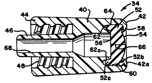
The pre-slit injection site 34 is formed with a cylindrical
housing 40 having a first end 42 and a second end 44.
Carried by the housing 40, adjacent the second end 44 is a hollow
cylindrical fluid flow member 46. The member 46 slidably engages a
receiving member in the housing 38 of the catheter 36, thereby
providing a sterile fluid flow coupling as is well known and
conventional.
A plurality of internal male luer-type threads 48 is carried by
the housi ng 40 adjacent the second end 44. The threads 48 wi 11 engage
the flange member 41 when the injection site 34 is rotated in a
direction 50. When so coupled together, the catheter 36 and the
injection site 40 provide a sealed coupling through which fluids may be
injected into the vein of the hand H.
Figure 3 illustrates, in section, further details of the
i nj ecti on si to 34. A reseal abl a septum 52 i s carri ed by the fi rst end
42 of the housing 40. The septum 52 includes first and second spaced
apart surfaces 54 and 56 respectively. The surface 54 has been forced
into a dome-like shape by annular, U-shaped, swaged end members 58
carried by the first end 42. The dome-like shape of the surface 54 can
extend beyond a surface 42a of the first end 42. This facilitates
cleaning the surface 54.
The septum 52 has a generally cylindrical shape. The septum 52
can be formed of a latex or synthetic rubber material. Alternately,
the septum can be formed of a thermoplastic elastomer. The material
used for the septum 52 should be non-toxic and sterilizable such as by
means of radiation, steam or Ethylene Oxide.
Because the septum 52 is generally cylindrical in shape, it can
be die-cut from a sheet, cut from an extruded rod or molded. The
septum 52 can have an exemplary diameter on the order of .30 inches
-15-
20~90~
(0.762 centimeters). The height of the septum 52 can be, for example,
on the order of .125 inches (.3175 centimeters).
The first end 42 is also formed with a tapered interior surface
60 which terminates in an annular channel 62. The tapered interior
surface 60 has a taper in a range of 5 degrees to 20 degrees.
Preferably, the taper will be on the order of 12 degrees. With the
indicated size of the above noted exemplary septum 52 and a 12 degree
taper, diametric resealing compression of the septum 52 adjacent the
channel 62 is on the order of 10'~t.
The channel 62 is bounded in part by a septum supporting ridge
62a. The channel 62 can typically have a depth in a range of .050-.070
inches (.127 - .1778 centimeters).
A peripheral surface 64 of the septum 52 slidably engages the
tapered i uteri or surface 60 as the septum 52 s 1 i des i nto the fi rst end
42. The annular channel 62 which underlies the interior peripheral
surface 56 of the septum 52 is provided to permit the septum 52 to
deform when a blunt cannula is inserted through an opening 66 therein.
The housing 40 is also formed with a fluid flow path 68 such that
fluids injected via a blunt cannula inserted through the resealable
opening 66 can flow into the catheter 36 for delivery to hand H of the
pats ent.
The swaged end members 58 apply axial forces to the septum 52
thereby creating the domed exterior peripheral surface 54. The axial
forces applied by the end members 58 slightly deform the regions 52a
and 52b. In contradistinction, the tapered internal surface 60 applies
radially directed forces to the septum 52, thereby forcing the opening
66 into a resealed condition.
In an alternate embodiment, the surface 52 could be formed as a
flat, as opposed to a domed, surface.
-16-
2~~~~~~
Once the infection site 34 is lockingly engaged with the catheter
36, a sealed system is formed through which fluids can be infused into
the catheter 36. The resealable septum 52 closes the fluid flow path
68.
Figures 4A and 4B illustrate in combination the infection site
34, a blunt shielded cannula 80 and a syringe of a conventional type
82. The syringe 82, as is well known, can be formed with a cylindrical
i hollow end 84 which carries a male luer-type twist lock thread 86. A
hollow centrally located cylindrical fluid flow member 88 is in fluid
flow cortmunication with an interior region 90 of the syringe 82.
The shi el ded bl unt cannula 80 carri es at a fi rst end 92 a femat a
luer twist-lock flange 94. The flange 94 will slidably engage the
threads 86 of the end 84. Hence, the shielded blunt cannula 80 can be
locked to the syringe 82 forming a closed fluid flow pathway. The
shielded cannula 80 could alternately be formed fixedly attached to the
syringe 82.
The shielded blunt cannula 80 carries a cylindrical hollow
protective shield 96 which surrounds a centrally located hollow,
elongated cylindrical blunt piercing member 98. The cylindrical blunt
pi erci ng member 98 has a total 1 ength on the order of three ti mes the
thickness of the septum 52 in order to ensure complete penetration.
The cylindrical blunt piercing member 98 has a diameter on the order of
1/3 the diameter of the septum 52. The shield 96 is desirable and
useful for maintaining the piercing member 98 in an aseptic condition
by preventing touch contamination prior to the shielded cannula 80
engaging the pre-slit septum 52. Also, the shield helps to align the
piercing member with the pre-slit septum.
The cylindrical blunt piercing member 98 can slidably engage the
pre-slit septum 52, best illustrated in Figure 4B, thereby extending
through the preformed opening 66 therein. As illustrated in Figure 4B,
_17_
~~3~~~~~
r r
when the piercing member 98 slidably engages and pierces the septum 52,
the region 52a deforms by expanding into and filling, at least in part,
the annular channel 62.
The deformation facilitates insertion of the piercing member 98
through the slit 66. Subsequent to the piercing member 98 slidably
engaging the injection site 34, the interior region 90 of the syringe
82 is in fluid flow communication with the flow path 68, of the
injection site 34 via flow paths 88a and 98a respectively of the
syringe and the blunt piercing member 98.
In this engagement condition, the septum 52 seals completely
around the piercing member 98. Hence, exterior gases, liquids or
airborne matter will be excluded from the channel 68.
Subsequent to infusing fluid from the syringe 82 into the fluid
flow pathway 68, hence into the catheter 36 and the hand H of the
pats ent, the syri nge 82 wi th 1 ocki ngly engaged shi el ded cannul a 80 can
be slidably withdrawn from the injection site 34. Subsequent to this
withdrawal, the septum 52 reseals the opening 56 therein.
The opening 66 will repeatedly reseal, when the piercing member
98 is removed, provided that the pressure (in the septum 52 of the
opening 66) created by interaction of the septum material properties
and compression supplied by the housing exceeds the pressure challenge
of the fluid contained within. Blunt cannula do not haphazardly core,
lacerate, or otherwise damage' the sealing interface 66 as conventional
needles do, thereby allowing repeatable resealability. However, septum
material properties, thickness, and compression allow resealability for
a finite number of conventional needle insertions. The combination
injection site 34 and catheter 36 then return to its pre-infusion,
sealed condition.
Fi gures 5A and 5B i 11 ustrate the pre-s 1 i t i n j ecti on s i to 34 used
in combination with a blunt cannula 80a. The cannula 80a includes a
hollow body portion 92a with a luer flange 94a, a piercing member 98a,
-18-
and manually operable elongated locking members 100a and 100b.
Alternately, a tubing member could be affixed to the hollow body
portion 92.
Curved end regions 100c of the members 100a and 100b slidably
engage the second end 44 of the housing 40 when the piercing member 98a
of the blunt cannula 80a has been forced through the pre-formed opening
66, best illustrated in Figure 5B. The embodiment illustrated in
Figures 5A and 5B has the advantage that the infusion cannula 80a
cannot accidentally disengage from the pre-slit septum 34 during the
fluid infusion process. It will be understood that while spring-like
deflecting members 100a and 100b are illustrated in Figures 5A and 5B
that other forms of locking members are within the spirit and scope of
the present invention.
Figure 6 illustrates an alternate pre-slit infection site 34a. A
tubing member 102 can be fixedly attached to the cylindrical hollow
fluid flow member 46. The embodiment 34a of Figure 6 utilizes the same
structure for the septum 52 including the tapered surface 60 and the
underlying annular channel 62 as does the embodiment 34 in Figure 3.
The shielded cannula 80 can be utilized with the infection site 34a as
previously described.
In the event that it is desirable to infuse solution from a
container 104 with a connectional port 106, a fluid administration set
110 of a conventional variety may be utilized. The set 110 includes a
spike connector 112 at a first end. The spike connector 112 is
designed to pierce the port 106 of the container 104. The set 110 can
also carry a slidably engageable connector 114 of a
known type at a second end. As illustrated in Figure 7, the
connector 114 can slidably engage the hollow cylindrical member 92
of the shielded cannula 80, thereby placing the interior fluid of
the container 104 into fluid conmunication with the tubing member
102.
Figure 8 illustrates yet another alternate 80b to the shielded
cannula 80. The piercing member 98 carries a tubing member 118
fixedly attached thereto. The tubing member 118 could be coupled at
a second end to a container such as the container 104.
_19_
i ~ ~ ~ ~ ~ ~ v
The present pre-slit injection site can be directly affixed to a
container 120 as illustrated in Figure 9. The container 120
includes a rigid hollow cylindrical access port 122 affixed
thereto. The access port 122 includes a fluid flow channel 124 in
fluid flow communication with the interior of the container 120.
Sealingly affixed to the port 122 is a pre-slit injection site 126.
The site 126 includes a cylindrical housing 128 which carries at
a first end 130 a septum 132 with a slit 134 formed therein. The
fi rst end 130 has been swaged to form an annul ar U-shaped retai ni ng
member 136. The retaining member 136 in turn forms a domed exterior
peripheral surface 138 on the septum 132.
The first end 130 also includes a tapered interior force
applying surface 140 and an annular channel 142 underlying the
septum 132. As discussed previously, the channel 142 provides a
space into which the septum 132 can deform when a blunt cannula is
forced through the resealable opening 134.
Further, as illustrated in Figure 9, the injection site 126 can
be covered by a removable cover 146 of a type used with the
conventional port 106 of the bag 104.
While the bag 120 is illustrated formed with two ports; the
conventional pierceable port 106 and the pre-slit injection site
126, it will be understood that as an alternate (Figure 10), a
container 150 could be formed which includes only the pre-slit
injection port 126. The removable cover 146 could be used in
combination with the container 150.
As illustrated in Figure 11, the pre-slit injection site 126 can
be utilized for the purpose of injecting fluid from the syringe 82,
coupled to the shielded cannula 80, into the container 150. When so
utilized, the blunt piercing member 98 is used to place the interior
fluid containing region 90 of the syringe into fluid flow
communication with the interior of the container 150.
Figures 12 and 13 illustrate a fluid flow coupling system 151
havi ng as a fi rst el ement a pre-s 1 i t i n j ecti on si to 126a. The s i
to
126a is the same as the site 126 except for a plurality of exterior
threads 153 formed on an exterior peripheral surface 155 of the
-20-
housing 128a. A second element of the coupling system 151 is a
shielded blunt cannuta 157.
The shielded blunt cannula 157 is sealingty affixed to a
flexible tubing member 159 by means of a proximal hollow cylindrical
member 161. The member 161 extends into a hollow cylindrical shield
163 to form a blunt piercing member 165.
The shield 163 carries, on an interior peripheral surface, a set
of coupling threads 165. The threads 165 match the threads 153.
The two connector elements 126a and 157 slidably engage one
another when the shielded cannula 157 moves in an axial direction
167 toward the infection site 126a. The blunt piercing member 165
penetrates the septum 132a.
The coupling member 157 can then be rotated in a direction 169
such the interior set of threads 165 carried thereon engages the
exterior set of threads 153. As a result, the two coupling members
126a and 157 are lockingly engaged together with the insertion
member 165 extending through the opening 134a in the septum 132a.
Hence, fluids can flow from the container 150a via the connector
system 126a and 157 through the tubing member 159 to the recipient.
In3ection sites of the type described above are also usable in
connection :with other fluid flow coupling components. For example,
with respect to Figure 14, a pre-slit in3ection site 160 of the type
described above can be used in combination with a spike connector
162 of a conventional variety. Spike connectors such as the spike
connector 162 can be used to pierce conventional ports such as the
port 106 of the container 104 (figure 6). When the spike connector
162 is so used, the pre-slit infection site 160 can then be utilized
for the purpose of coupling to other fluid administration sets.
The infection site 160 illustrates an alternate form of swaging
the first end 42c for the purpose of retaining the septum 52c
therein. The first end 42c can be swaged so as to form an annularly
shaped, spiral, spring-like member 164. The member 164 has a free
end 164a which=engages the exterior dome-shaped peripheral surface
54c of the septum 52c. The spiral, spring-like swaged member 164
-21-
20~~~f
r
will tend to uncoil, thereby continuously applying axial force to
the septum 52c and maintaining the domed exterior peripheral surface
54c.
In yet another alternate, Figure 15 illustrates a pre-slit
infection site 166 formed in a Y-function member 168. The
Y-function member 168 is fixedly attached to first and second tubing
members 170 and 172 respectively.
As an alternate to forming the slit 66d completely through the
septum 52d, as illustrated in Figure 16, a slit 66e can be formed
only partly through the septum 52e. Such a structure has the
further advantage that, until used for the first time, the septum
52e is completely sealed.
The septum 52e can be formed in two parts. One part can have a
slit, such as the slit 66e, extending entirely therethrough. A
second part can be formed without a slit. These two parts can be
located adjacent one another in the first end 42e of the infection
site.
The slit 66e may be longer on the top of the septum than the
j bottom. This feature aids blunt cannula alignment with the slit
upon insertion, and aids resealability by minimizing the critical
slit sealing interface area.
In accordance wi th the present i nventi on, the s 1 i t coul d have a
length with a range on the order of .03 inches (.0762 centimeters)
to .150 inches (.381 centimeters). Preferably, a slit length on the
order of .07 inches (.1778 centimeters) will be used in combination
with a blunt cannula having a diameter on the order of .1 inches
(.254 centimeters).
When initially used, the blunt cannula piercing member, such as
the member 98, will be forced through the slit 66a. The lower
peripheral surface 56e will then be punctured, providing access for
the blunt cannula piercing member 98 into the fluid flow pathway 68e.
Pre-slit infection sites of the type described above can be
utilized in combination with burette solution administration sets.
One such set 176 is illustrated in Figure 17. The set 176 includes
a pre-slit infection site 178 of the type described above. The
-22-
2~1~9~63
infection site 178 is affixed to an exterior planar surface 180 of
the burette 182. A removeable cover 184 can be used to maintain the
infection site 178 in an aseptic condition until blunt cannula 186
or 188 is inserted therethrough.
Figures 19 through 23 disclose a method of making a pre-slit
infection site in accordance with the present invention. In a first
step, a housing 200 is provided. The housing 200 has an interior
tapered surface 202 at a first end 202a thereof. The interior
peripheral surface terminates in an annular channel 204. A
cylindrical septum 206 can be provided adjacent the end 200a.
In a second step, the septum 206 can be forced into the end 202a
of the housing 200 and slightly deformed by the tapered peripheral
surface 202 using an axially moving die 210. When positioned by the
die 210, the septum 206 is located adjacent an internal annular
right 212 which bounds the annular channel 204.
In a thi rd step, a second di a 214 can be uti 1 i zed to swage the
end 200a into spiral-shaped, spring-like members 200b which apply
axially directed forces against an exterior peripheral surface 206a
of the septum 206. The axially directed forces form the flat
surface 206a into a domed exterior peripheral surface 206b as
illustrated in Figure 23.
Simultaneously, with swaging the end members 200a so as to lock
the septum 206 into the housing 200 and to form the domed exterior
peripheral surface 206b, a knife 216 can be utilized to form a slit
in the septum 206. Alternatively, the slit may be cut by a separate
die in a separate step. If the septum 206 is formed as an
extrusion, the slit can be created during the extrusion process. If
the septum 206 is formed by stamping from a rubber sheet, the slit
tan be cut during the stamping process. If the septum 206 is formed
by compression molding, the slit can be cut during the trimming
process.
In order to extrude the slit into rod, a flat pin extrusion
bushing can be used. A trailing ribbon may be attached to the
bushi ng. The ri bbon would prevent curs ng maters al across the si i t.
The ribbon or wire could be placed in the rod core and later
-23-
2~4~~b~
stripped out leaving a slit. An inert substance, such as silicone
oil, could be coextruded in the center of the rod to prevent curing
across the slit and provide lubrication and a visible target for
cannula insertion.
Figures 24 and 25 illustrate alternate swaging steps wherein a
die 220 moving axially toward the housing 200 swages the end region
200a so as to form an annular U-shaped region 200c and the exterior
domed peripheral surface 206c.
The dies 214 or 220 can be formed with various alternate shaped
swaging surfaces 224, as illustrated in Figure 26, depending on the
precise shape of the end swage which is desired. It will be
understood that all such variations in the swaging operation are
within the spirit and scope of the present invention.
The injection site configuration need not be limited to the
configurations depicted in Figures 3 through 5B, 9, and 12 through
16. Rather, several configurations could be constructed without
departing from the scope of this invention. Any such configuration
would provide a flexible pre-slit sealing member captured in a
housing which provides compression to create a seal against pressure
and a void region to accommodate deformed portions of the sealing
member material only when the material is deformed or displaced by a
blunt cannula piercing member. One such possible configuration is
depicted in Figures 27 and 28.
Figures 29 and 30 illustrate a tapered cannula structure 250
which is an alternate to the tapered cannula 98. The cannula 250
includes a proximal end 252 with an interior region 254. The region
254 i s i n part bounded by an i nternal pert pheral wal 1 256 whi ch i s
formed with a standard luer taper. The tapered cannula 250 can be
formed with a luer-type coupling flange 257 at the proximal end so
as to be releasably connectable to the syringe 82 as was the tapered
cannula 98 previously discussed.
Extending from the proximal end 252 is a cylindrical tube having
a cylindrical mid-region 258 and a distal end member 260. The
-24-
C.
member 260 has a generally elongated, cylindrical shape with an
exterior side wall 262. A centrally located, cylindrical, internal
fluid flow path 264 extends through the distal end member 260 and
mid-region 258 in fluid flow communication with the interior region
254.
The distal end of the end member 260 has a tapered exterior
surface 266. The tapered exterior surface 266 minimizes insertion
force as the cannula 250 is berg forced through a slit of a septum,
such as the slit 66 in the septum 52. The angle of taper of the
surface 266 is preferably in a range between 1 to 15 degrees.
The member 260 is also provided with a plurality of elongated
grooves 268. The grooves 268 in the exterior wall of the member 260
decrease the surface area of contact at the cannula/septum interface
during insertion of the cannula into the infection site 34. This
reduced exterior contact surface area decreases the frictional
component of the insertion force.
In one embodiment, the tapered blunt cannula 250 may have
overall insertion length, corresponding to combined axial lengths of
mid-region 258 and end member 260, on the order of 0.375 inches
(.9525 centimeters).
An alternate cannula structure 280 is illustrated in Figures 31,
32, and 33. The cannula structure 280 includes a proximal end
region 282 corresponding to the end region 252 of the cannula 250.
The region 282 includes a luer flange 283. The cannula 280 also
includes a central, elongated, cylindrical region 288.
The central region 288 carries at a distal end thereof an
elongated cylindrical end member 290. The member 290 includes an
exterior, peripheral, cylindrical surface 292 (Figure 31). The
surface 292 is interrupted by a plurality of spaced-apart, elongated
slots or apertures 294. The slots 294 are defined by first and
second spaced-apart, elongated, parallel side surfaces 294a and
294b. Each of the slots terminates in an end surface 294c at the
central region 288.
A fluid flow path 294d extends through the cannula 280. The
flow path 294d is in fluid flow conununication with the slots 294.
-25-
I
Between the slots 294, at a distal end of the region 290, the
exterior surface 292 terminates in tapered end regions 298 to
facilitate insertion of the cannula into a pre-slit injection site.
The slots 294 themselves also function to decrease the surface
contact area, and this further minimizes the insertion force.
The slots 294 are oriented substantially 90 degrees apart around
a longitudinal axis 300. The slots 294 increase the internal flow
path cross-section. This increases the fluid flow rate.
The slots 294 also provide for enhanced dispersion
characteristics owing to the fluid flowing radially out through the
slots 294. This radial flow, effecting as change in fluid flow
direction of about 90 degrees, promotes flushing and dispersion of
fluid through the injection site 34.
Another embodiment of a blunt cannuta 310 is illustrated in
Figures 34 through 37. The cannula 310 is formed with an enlarged
proximal connection region 312 corresponding to the region 252 of
the cannula 250. The region 312 includes a luer flange 313 and a
central fluid flow region 314.
An intermediate, cylindrical region 318 extends from the
proximal connection region 312. The cylindrical intermediate region
318 includes a fluid flow path 320 in communication with the fluid
flow region 314.
The end region 324 extends from the region 318 and includes a
first cylindrical portion 326 into which the fluid flow path 320
extends. The region 326 terminates in a tapered exterior surface
328. The tapered exterior surface 328 merges with a centrally
located lead post or guide post 330. The lead past 330 terminates
in a hemispherical end surface 332.
The lead post 330 helps locate the septum slit 66 prior to
insertion and facilitates penetration of the septum slit 66 by the
cannula. The lead post 330 facilitates insertion by providing a
very low insertion force at the beginning of the insertion step as
the cannula is pushed through the slit, such as the slit 66.
In a preferred embodiment, the guide post 330 can have a length
on the order of 0.060 inches (.1524 centimeters) and a diameter on
the order of 0.050 inches (.127 centimeters).
-26-
The end region 318 includes a novel structure for increasing the
flow rate and enhancing dispersion characteristics. In particular,
the region 318 includes three radially oriented slots 338. Each
slot 338 has sides 339a and 339b which each lie along a radius of
the cylindrical portion 326 as best illustrated in Figure 37. The
fluid flowing through the cannula 310 undergoes a change in
direction (of up to about 90 degrees relative to the cannula center
line 337) in the slots 338. This change in direction increases
fluid dispersion. Further, since the slot 338 open radially, fluid
flow can be maintained even if the end surface 332 of the cannula is
pushed up against any material in the system in which the cannula is
inserted.
Another embodiment of the tapered cannula of the present
invention is illustrated in Figures 38 through 40 and is designated
generally therein by reference numeral 340. The cannula 340
includes a proximal end 342 which can include a luer coupling flange
344 for cooperating with a suitable mating structure on a syringe.
The proximal end 342 also defines an interior region 346.
Extending from the proximal end 342 is a generally cylindrical
mi d-regi on 348. Extendi ng from the mi d-regi on 348 i s an end member
or region 350 which includes a tapered surface 352.
The distal end of the end region 352 terminates in a blunt,
arcuate end surface 356. Defined within the mid-region 348 and end
region 350 is an internal fluid flow channel 354 which communicates
with the interior region 346. Fluid discharges from the flow
channel 354 via grooves or apertures 358 in the end region 350. The
change in direction of the fluid flow as the fluid passes from the
interior channel 354 through the apertures 358 improves fluid
dispersion with respect to mixing or flushing in the system
downstream of the cannula (e. g., the infection site, drug vial,
etc.). The apertures 358 may also function to increase withdrawal
force or tug resistance.
Moreover, since the fluid passes radially out through the
apertures 358, fluid flow through the cannula 340 can be maintained
even when the distal end surface 356 of the cannuta is bottomed out
-27-
or pushed against any material in the system in which the cannula is
inserted.
The structure of the cannula 340 is adapted to be constructed
with a minimal lead post length (i.e., the portion of the cannula
distal end between the end surface 356 and the interior flow channel
354). Further, the design accommodates the use of a minimal tip
diameter, minimal taper angle, and minimal cannula diameter. The
minimization of these parameters results in a decrease in the peak
insertion force required to properly install the cannula in the
injection site.
Preferably, the total cross-sectional flow area through the
three apertures 358 is about three times the cross-sectional flow
area of the interior channel 354. This enhances the flow rate
capability compared with a simple open ended cylindrical flow
channel of equal length.
The design of the cannula 340 also is effective in reducing or
limiting "kick back" or recoil of the cannula after insertion. The
resilient material of the septum in an injection site can subject
the cannula to forces tending to push the cannula back out of the
septum. The kick back forces on the cannula 340 are minimized by
the provisions of the generally cylindrical mid-region 348.
Another embodiment of the cannula of the present invention is
illustrated in Figures 41 and 42 wherein the cannula embodiment is
designated generally therein by the reference numeral 360. The
cannul a 360 i ncl udes a proxi mal end 362 defi ni ng an i uteri or regi on
364 and having a luer flange 366 for connection to a suitable mating
engaging structure.
A generally cylindrical mid-region 366 extends from the proximal
end 362, and an end region 368 extends from the mid-region 366. As
with the previous embodiment of the cannula 340 illustrated in
Figures 38 through 40, the embodiment of the cannula 360 minimizes
kick back or recoil owing to the provision of a substantially
cylindrical mid-region 366. This design also increases withdrawal
or tug resistance.
A generally cylindrical internal flow channel 370 extends
through the end regi on 368 and mi d-regi on 366 i n communi cats on wi th
-28-
the interior region 364 of the proximal end region 362. The end
region 368 is provided with a tapered surface 372. The design
permits the use of a very small taper to minimize the insertion
force.
Further, the design permits the cannula 360 to be constructed
with a small tip diameter, small taper angle, and small cannula
diameter so as to reduce the peak insertion force.
Another embodiment of the cannula of the present invention is
illustrated in Figures 43 through 44 and is designated generally
therein by reference numeral 380. The cannula 380 includes a
proximal end 382 with a luer flange 384. An interior fluid flow
region 386 is defined on the interior of the proximal end 382.
Extending from the proximal end 382 is a mid-region 388. A
distal end region 390 extends from the mid-region 388. An internal
fluid flow channel or path 392 extends through the end region 390
and mi d-regi on 388, and i s i n conmuni cats on wi th the i nteri or fl ow
region 386.
The end region 390 has an exterior tapered surface 394. This
facilitates insertion of the cannula into the infection site. In
contrast, the mid-region 388 is generally cylindrical so as to
minimize kick back and increase the withdrawal force or tug
resistance.
Further, to provide even greater withdrawal force, the
mid-region 388 includes an annular barb 396. The barb 396 has a
sufficient radius so as to preclude damage to the septum of the
infection site and so as to accommodate molding in a straight draw
tool. The maximum diameter of the annular barb 396 may typically be
on the order of 0.02 inches (.0508 centimeters) greater than the
diameter of the cylindrical mid-region 388. Although the barb 396
functions to prevent inadvertent removal of the cannula 380 from the
septum of the infection site, removal of the cannula 380 can still
be achieved by entering a sufficiently great axially directed
removal force on the cannula 380.
Still another embodiment is illustrated in Figure 45 which
includes a blunt tapered cannula insertion member 400 for insertion
-29-
2Q~~Q~~
i nto a pre-s 1 i t i n3 ecti on si te, the cannul a 400 havi ng a di stal end
region 402 with a tapered exterior surface which in the preferred
embodiment is an approximately 8 degrees taper. The defined
aperture 404 for fluid flow is disposed at the end 406 of the distal
end region 402. The end 406 includes a radiused tip defined by a
radius of approximately 0.01 inch (.025 centimeters). The radiused
tip reduces insertion force, assists in locating the slit in the
in3ection site and in addition has the practical advantage of
facilitating complete filling of the cannula mold cavity.
The tapered surface of the distal end region 402 has an axial
length of approximately 0.10 inch in the preferred embodiment,
Adjacent to the tapered distal end region is a generally cylindrical
region 408 for entering into the infection site behind the distal
end region 402, thereby reducing kick back during insertion. The
generally cylindrical region 408 has a small draft angle such as
about one-half degree.
The force required to insert any of the above-discussed
embodiments of the blunt tapered cannula into the septum of the
infection site depends upon a number of factors: friction at the
cannula/septum interface, cannula diameter, cannula taper angle, and
degree of septum compression. The cannula/septum interface friction
is, in turn, dependent upon lubrication, if any, material
properties, and surface finish. It will be understood that the
friction at the cannula/septem interface can be reduced by providing
a smoother surface finish on the cannula (e.g., by sand blasting the
cannula exterior surface) or by molding the cannula so as to produce
a matte finish. Conventional lubricants can also be used to further
reduce the friction and thereby lower the insertion force required.
In the embodiments of the cannulae described herein, the
mid-region and -the tapered distal end region may be alternatively
characterized as together forming at least one tube defining a fluid
i, flow path therein with the tube having a distal end region for
penetrating the infection site.
-30-
204~~t~3
In preferred contemplated embodiments, the exterior surface of
the di stal end region may have a taper angl a as smal 1 as between 1
and 15 degrees.
Further, a locking means, such as the locking arms 100a and 100b
discussed with reference to Figures 5A and 5B, may be provided on
the cannula embodiments illustrated in Figures 29 through 44 to
permit the cannulae to be releasably locked to the injection site.
The above described insertion members, usabie as part of a blunt
cannula, are preferably molded of a plastic formulation including
silicone or other lubricant. The use of silicone or other lubricant
increases the ease of insertion of that member into the pre-slit
injection site.
Figure 46 shows a blunt cannula member, generally at 410, for
use with the pre-slit injection sites disclosed herein. The blunt
cannula member 410 generally has a hollow cylindrical portion 412
and a blunt cannula portion 414. The blunt cannula member 410 is
preferably~of one-piece molded, rigid plastic, with a through bore
416 extending through the blunt cannula portion and communicating
with the hollow cylindrical portion.
The hollow cylindrical portion has a pair of opposed raised
flanges or threads 418 for threaded engagement with other devices,
for example, syringes, administration sets and the like.
Internally, the hollow cylindrical portion 412 may also be adapted
for attachment to other devices. For example, the internal surface
of the cylindrical portion may define a tapered female luer surface
for interfitting with the standard male luer connectors utilized in
many medical devices, as is well known in the medical field. The
hollow cylindrical portion 412 may also include a pair of opposed
flat surfaces 420 for cooperation with a tip protector or shield
such as depicted in Figure 47, which is described below.
-31-
w~~~~~c~J
The blunt cannula portion 414 extends generally axially from the
hollow cylindrical portion 410. The cannula portion is generally
cylindrical throughout the greater part of its length, with a
tapered end portion 424, which narrows to the blunt end edge 426.
Figure 47 is an enlarged view of a hollow shield or tip
protector 428 for covering and protecting a blunt cannula, such as,
for example, the blunt cannula portion 414 of blunt cannula member
410 shown at Figure 46 or other blunt cannulae as disclosed herein.
The shield 428 has a generally elongated housing 430, which is open
at one end for receiving the blunt cannula. At the open end, the
interior surface 432 of the shield generally corresponds to the
shape of the exterior surface of the blunt cannula portion 412,
i.e., it is generally cylindrical, with a pair of opposed flat
surfaces 434 matching the flat surfaces 420 of the blunt cannula
device 410. Further, either surfaces 432 or 434 can be provided
with standing ribs to control the depth of insertion of the blunt
cannula portion 414 into housing 430. The matching flat surfaces of
the shield and the blunt cannula device allow a user to secure the
blunt cannula onto a syringe or similar device, for example, without
exposing the cannula portion 414 to touch contamination. When
access to the blunt cannuta is required, the shield may simply be
slidably removed from the cannula. As can be appreciated, the outer
surface of the shield 428 can be shaped in such a manner or provided
with a roughened finish to assist the user in gripping or removing
shield 428 from the cannula. .
Typically, the blunt cannula 410 or other blunt cannula device
and shield 428 would be provided in a joined sterile configuration.
The shield 428 can be provided with channels to facilitate gas
sterilization. The user preferably leaves the shield on to prevent
inadvertent contamination when attaching the blunt cannula to the
mating product, e.g., the male luer fitting of a syringe or
administration set. The matching flat surfaces 432 of the shield
-32-
w
f
and 420 of the bl unt cannul a act as a wrench to al 1 ow any twi sti ng
force appl i ed to the shi el d to be transmi tted to the cannul a, e.g. ,
for threading the cannula onto a luer lock device or for applying a
twisting force in making a luer slip connection.
Fi gure 48 shows what i s conmonly referred to as a hepari n 1 ock,
general 1 y at 436, empl oyi ng a pre-s 1 i t i n~ ecti on s i to 442 and
other
features of the present invention. The heparin lock 436 may be
attached, for example, to the end of a venous catheter.
During intravenous therapy, it is not unusual for the
administration of liquid to be interrupted from time to time.
Instead of performing a new catheterization procedure each time
administration is to be restarted, it is often preferable to utilize
the same catheter, thus reducing the number of catheterization
procedures, more colloquially referred to as the number of "sticks,"
and reducing the trauma and risk associated with each such procedure.
To maintain the patency of the catheter during interruption, and
prevent blood from clotting and clogging the catheter, it is a
common practice to attach an infection site over the catheter an
fill the catheter with heparin or other anticoagulant. The heparin
lock 436 shown in Figure 48 is for attaching to a patient's catheter
for maintaining patency of the catheter during interruption in fluid
flow.
The heparin lock 436, also shown in Figures 49 and 50, has a
first end portion 438 in the form of a male luer connector for
sealingly engaging a complementary female tapered luer surface on
the patient's catheter (see cross-sectional view in Figure 50). The
other end of the heparin lock 436 includes a pre-slit infection site
442 of the type previously discussed in detail. An axial fluid flow
passageway 444-communicates between the pre-slit infection site and
the end of the male luer for fluid flow therebetween.
-33-
~~~~6~
The tapered exterior surface of the male luer 438 is
substantially surrounded by generally cylindrical gripping collar
446. Threads 448 are provided on the interior surface of the collar
for threadedly engaging a standard luer lock connector, as is often
found on intravenous catheter devices. The exterior surface of the
collar 446 is generally arcuate in cross-sectional shape (as best
seen in Figures 49 and 50), to provide a gripping surface. The
surface curves generally outwardly in a direction toward the
pre-slit injection site 442. This allows the nurse, physician or
attending staff member to grip the heparin lock and to reduce any
force exerted during entry of a blunt cannuta into the pre-slit
injection site form being transmitted to the venous catheter. For
improvement in the gripping, a series of axial grooves 450 are
provided in the exterior surface of the collar 446.
In accordance with other aspects of the present invention, the
heparin lock includes features which allow attachment to various
styles or types of blunt cannulae. For example, as best seen in
Figure 48, threads 452 are provided on the exterior surface of the
cannula for' threaded locking engagement to a blunt cannula device of
the type having an interiorly threaded sleeve or shield, such as
depicted in Figure 50. The heparin lock 436 also includes a
generally radially-extending shoulder 454 for locking retention of
resilient gripping fingers on a blunt cannula device of the type
shown in Figure 49.
As a safety measure, and to prevent staff confusion of an
injection site of the present invention with other injection sites
which are for use with needles, a visual identifier is also provided
with the heparin lock of Figure 48. Such an identifier may also be
provided with the other pre-slit injection site devices described
above. The identifier may take the form of any unique color or
configuration which allows the staff member to determine that the
heparin lock 436 embodies the present invention and is
-34-
~~~~~J
intended for use with blunt cannulae. In the preferred embodiment,
however, the visual identifier comprises a distinct color identifier
and, more particularly, is a brightly colored ring 456 (Figure 48)
circumscribing the pre-slit infection site 442. While the color
selected may vary depending on application, it should be a color
which is distinct from and in contrast to the color of any plastic
used in the manufacture of the heparin lock.
As noted earlier, the heparin lock 436 depicted in Figure 48 may
be used with a variety of styles or types of blunt end cannula
devices. For example, the heparin lock may be used with a bare
blunt end cannula, such as that depicted in Figure 46, which does
not lock onto the heparin lock. Alternatively, as shown in Figure
49, the heparin lock may be used in combination with a blunt cannula
device 458 which utilizes a pair of resilient gripping fingers 460
for retaining the blunt cannula in joined relationship with the
heparin lock. The blunt cannula device 458 depicted in Figure 49
has a generally cylindrical, hollow base or body portion 462 and a
blunt cannula portion 464 substantially as described earlier in
connection with Figure 46 or with the other figures of the present
inventions: A fluid flow path 463 extends through the blunt cannula
portion and communicates with a female luer connection 465 defined
in the hollow body portion for fluid flow through the blunt cannula
device. Flanges or threads 467 on the body portion permit the
attachment of a male luer lock connector to the blunt cannula device.
Each of the gripping fingers 460 is mounted to the body portion
of the blunt cannula device by an intermediate radially extending
wall portion 466. The gripping fingers have radially inwardly
di rected retention means 468 at one end for engagi ng agai nst radi al
shoul der 454, and gri ppi ng means 470 at the other end for squeezi ng
and spreading the retention means to release the blunt cannula
device from the heparin lock. In the as-nblded condition, the
gripping fingers are biased radially inwardly, toward the blunt
cannula portion 464. Because of the natural resilience of the
-35-
plastic, the retention end of the fingers may be spread by squeezing.
the gripping end of the fingers. The natural resilience will hold
the retention means in the lock position (shown in Figure 49) until
manually released.
When used in combination with a heparin lock such as depicted in
Figure 48, the blunt cannula device 458 may be attached by simply
pushing the blunt cannula into the pre-slit in3ection site 442. A
forward facing tapered surface 472 (Figure 49) in front of the
threads engages a similar tapered surface 474 on the retention means
468 so as to naturally spread the fingers 460 apart as the blunt
cannula is forced into the pre-slit infection site. After the blunt
cannula is inserted into pre-slit infection site sufficiently far so
that the retention means are beyond the radial shoulder 454, the
gripping fingers will snap inwardly behind the shoulder, holding the
blunt cannula in the position depicted in Figure 49. To withdraw
the blunt cannula, the user need simply squeeze the gripping end 470
of the handles, which will spread the retention means of the fingers
and release the blunt cannula device from the heparin lock.
The heparin lock of Figure 48 is also useful with a blunt
cannula device 475 having an internally threaded shield or sleeve,
such as depicted in Figure 50. Figure 50 illustrates the blunt
cannula device 475 as it first enters the pre-slit infection site
442 of the heparin lock and prior to engagement with the heparin
lock threads 452. the blunt cannula device shown in Figure 50 has a
generally cylindrical outer wall 476 and a transverse end wall 478.
A blunt cannula 480 extends through the end wall. The blunt cannula
may be constructed in generally the same manner as the blunt cannula
portion depicted in Figure 46 or in accordance with the other
embodiments of the present invention.
The cylindri cal outer wall 476 preferably extends beyond the tip
end of the blunt cannula to protect the cannula against inadvertent
touch contamination. The interior surface of the cylindrical wall
-36-
is preferably threaded at 482 for threadedly engaging the device to
which the blunt cannula is attached, such as the heparin lock
depicted in Figure 48. As noted above, Figure 50 depicts the blunt
cannula device 475 at an initial entry position. Further insertion
of the blunt cannula and simultaneous turning of the blunt cannula
device results in threaded locking engagement between the blunt
cannula device 475 and the heparin lock.
The blunt cannula 480 of the blunt cannula device 475 is in
fluid communication with an entry port, generally defined by wall
484, which extends in the opposite direction of the blunt cannula,
from the other side of the transverse wall. The entry port is for
attachment to other devices such as syringes, tubing, administration
sets or the like, and may take such form as is appropriate for the
particular device to which it is attached. The entry port 484
preferably has a tapered inner surface for receiving a standard male
luer fitting of a syringe or the like, and may include external
threads or flanges 485 for attachment to a luer Lock. Another
embodiment provides the entry port 484 as having a tapered inner
surface for receiving a tubing fit. A fluid passageway 486 extends
continuously through the entry port and the cannula portion for flow
therebetween.
Figure 51 shows, in cross-sectional view, a further alternative
device 492 which may employ the pre-slit infection site of the
present invention. The pre-slit infection site device 492 depicted
in Figure 51 is an in-line device, preferably for adding medication
to a fluid stream, removing a sample from a fluid stream, or similar
application. The device depicted in Figure 51 has a fluid entry
port 494 at one end, a fluid exit port 496 at the other end, and a
fluid passageway 498 communicating directly between the entry and
exit ports. The inlet and outlet may have such additional features
as are useful zonnecting the infection site device within a fluid
flow path. As depicted, the inlet defines a slightly tapered female
surface and the outlet defines a similarly female tapered surface
-37-
N
I
which are preferably joined by solvent bonding a similar attachment
to plastic tubing of an administration set, extension set or the
1 i ke. Standard 1 uer fi tti ngs or surfaces coul d al so be provi ded at
the inlet or outlet, as desired.
For injecting liquid into the fluid stream or sampling the fluid
stream, the device has a side channel 496 which communicates between
a pre-slit septum 502 made and assembled in accordance with the
present invention, and the fluid passageway 498. The septum 502 is
made as described above, and mounted and held in position by a
swaged-over wall 504, as previously described, which may include a
colored identifier ring around the septum.
In accordance with the present invention, a blunt cannula, such
as cannula 506, may be inserted through the pre-slit septum for
injecting fluid into the liquid stream flowing between the inlet and
outlet, or for taking samples of the fluid stream.
The i n-1 i ne i n j ecti on si to devi ce 492 shown i n Fi gure 51 may be
used in combination with a bare blunt cannula, such as that depicted
in Figure 51, or may be used in combination with the blunt cannula
device 458, depicted in Figure 49, when a locking relationship
between the blunt cannuta and injection site is desired.
As depicted, for example, in Figure 52, the blunt cannula device
458 may be attached i n a secure 1 ocki ng rel ati onshi p to the i n-1 i ne
injection site 492. As shown there, the in-line injection site has
a radially extending shoulder 508 on each side of the housing, for
engaging against the retention means 468 on the end of the resilient
gripping fingers 460. As with the heparin lock, the in-line
injection site also includes a generally tapered surface 510 defined
on the exterior surface for spreading the retention means as the
blunt cannula i's inserted into the injection site. As was described
above, insertion of the blunt cannula into the injection site
results in the retention means being spread by the tapered surface
-38-
~~~~~c~J
510 and, as the blunt cannula is inserted farther, the retention
means snap into a locking position behind the radial shoulder 508.
In this arrangement, the blunt cannula is securely locked onto the
in3ection site and inadvertent withdrawal is thus prevented. To
remove the blunt cannula from the in-line infection site, the
gripping ends 470 of the resilient fingers are squeezed, causing
spreading of the retention means 468 and release from the infection
site. The cannula may then be simply removed by withdrawing it from
the infection site.
Figure 53 depicts yet a further embodiment of the present
invention. That figure depicts a blunt cannula device 512 embodying
the present i nventi on i n combs nati on wi th a syri nge 514. The bl unt
cannul a devi ce 512 has a general 1 y cyl i ndri cal outer wall 516 whi ch
encloses and substantially protects a blunt cannula portion 518.
The blunt cannula portion is attached to and extends from an
intermediate transverse interior wall 520. The blunt cannula device
512 may be attached to a syringe in various ways. As depicted,
however, the syringe 514 has a glass barrel wall which is tightly
press fit into one end of the cylindrical outer wall, extending
therewithin~to the transverse wall 520.
Although various syringes may be used in connection with the blunt
cannula device 512 without departing from the present invention, the
syringe depicted in Figure 53 is of the type prefilled with a
medical liquid such as heparin. Although it does not form a part of
the present invention, for purposes of completeness, the syringe
depicted in Figure 53 has a pair of resilient pistons 522 spaced
apart, with the fluid to be dispensed contained between the
pistons. A plunger rod 524 pushes the pistons forward until the
forward most pi ston engages agai nst an entry port 526 whi ch extends
in a direction opposite the blunt cannula 518. The forwardmost
' piston has a frangible portion, which is pierced by the entry port,
releasing the liquid contained between the pistons for expulsion
through the blunt cannula.
-39-
2~~~~~~~
In accordance with the present invention, the blunt cannula
portion 518 is substantially protected from inadvertent touch
contamination by the outer cylindrical wall 516. To permit the
blunt cannula to be used, however, with the in-line in3ection site
492 or a similar device, a pair of opposed, generally U-shaped
recesses 528 are provided in the cylindrical wall for receiving the
inlet and outlet portions 494, 496 of the in-line in3ection site
when the cannula is attached to it. This arrangement is depicted in
a perspective view in Figure 56. As shown there, the blunt cannula
device 512 may be attached to the in-line infection site by
inserting the blunt cannula portion into the pre-slit infection
site, with the U-shaped recesses 528 receive the inlet and outlet
portions 494, 496 of the in-line infection site, thus allowing the
bare cannula to be inserted sufficiently far into the pre-slit
infection site.
Figure 54 shows a shield or tip protector 530 for a blunt
cannula device of the type shown in Figure 53. The tip protector
530 has a generally cylindrical outer wall 532 with raised ribs 534
for gripping. The cylindrical wall is sized to slip over the end
cylindricalv wall 514 of the blunt cannula device 512, and is
sufficiently long to extend beyond the U-shaped recesses to
completely enclose and protect the blunt cannula 518 during
shipping, storing and between uses, if so desired.
Concentrically disposed within the cylindrical wall 532, the tip
protector has an axially extending, hollow tube 536 for slidably
receiving the blunt cannula 518 therewithin. The shield or tip
protector 530 would typically be attached to the blunt cannula
device 512 during manufacture, and removed when the syringe and
blunt cannula device are used. If so desired, it may be reattached
between uses to protect the cannula from any further contamination.
Figure 55 is an alternative embodiment of the blunt cannula
device shown in Figure 53, and is depicted without a syringe
-40-
CA 02049063 1999-09-22
attached to it. As shown in Figure 55, the blunt cannula device 538 similarly
has a
cylindrical outer wall 540, a transverse intermediate inner wall 542, a blunt
cannula
544 extending axially from the transverse intermediate wall and an entry port
546
extending in the opposite direction from the blunt cannula. The essential
difference
between this embodiment and the one shown in Figure 53 is the absence of the
U-shaped recesses for use with an in-line injection site such as depicted in
Figure
56. For ease of attachment to an injection site, the inner surface of the
cylindrical
wall is preferably tapered at 548.
The in-line injection site device 492 shown in Figure 51 is ideally suited for
use in an arterial or venous line blood sampling system such as the one
disclosed in
USPN 4,673,386 entitled Blood Sampler Device, issued, June 16, 1987, in the
name
of Mark Cordon.
The in-line injection site device 492 of the present invention would replace
the
stopcock or three-way valve 49 of the Cordon patent at the blood withdrawal
site.
Figure 57 shows the blood sampling system of the present invention with the in-
line
injection site device 492. The fluid entry port 494 and fluid exit port 496 of
in-line
injection site 492 are preferably joined to the plastic tubing 555 of the
administration
set by solvent bonding, as opposed to standard luer fittings, to reduce the
risk of
contamination. Using the pre-slit injection site of the present invention
rather than a
conventional stopcock at the blood withdrawal site also reduces the risk of
contamination.
Referring to Fig. 57, the blood sampling system of the present invention
includes a blood reservoir assembly 550, an in-line injection site device 492
(sampling site), a shielded blunt cannula
-41-
577 with syringe 582, and a blood transfer unit 552. The reservoir
and sampling site are connected via bonded connections to pressure
tubing 555 which is in turn bonded to a female luer connector 551 at
the inlet side of the reservoir for attachment to a pressure
transducer (not shown). The transducer is positioned in-line
between the reservoir and a flush valve, downstream from a fluid
supply. A male luer connector 553 is bonded to the pressure tubing
at the outlet side of the sampling site for attachment to a patient
catheter. The entire system is intended to be disposable.
As disclosed and described in the Gordon patent, the reservoir
is an in-line syringe type device with housing, cap, plunger and
seal which when actuated draws into the internal cavity a
blood/saline mixture of approximately 5 cc for the standard adult
and approximately 3 cc for the pediatric patient. The fluid is
drawn from the patient side as opposed to the transducer side due to
the high fluid restriction provided by a micro-bore hole which
exists in currently manufactured flush devices. This clears the
line between the patient and the sampling site of saline solution or
other IV fluid and therefore permits a pure blood sample to be taken
from the sampling site. After the sample has been taken, the
blood/saline mixture in the reservoir is returned to the patient.
The present invention preferably provides a sampling site
housing in the shape of a "Z" as shown in Fig. 58, although the
T-shaped housing shown in Fig. 51 may also be used. The "Z" housing
558 has an inlet port 560 at the bottom leading to the reservoir and
an outl et port 562 at the top 1 eadi ng to the pats ent to provi de for
ease of debubbling during initial filling of the patient line with
fluid and ease of blood clearing from the reservoir following the
sampling process. The top portion 564 of the housing contains a
pre-slit septum 566 made and assembled in accordance with the
present invention and specifically as shown in Fig. 51. An arm or
pole mount plate 568 may also be provided for holding the sampling
site housing. In a preferred embodiment, the bottom portion 570 of
_42_
i
i
the housing mates with and is bonded to raised pedestal 572. Cradle
574 may also be provided in the mounting plate, if desired, to
receive inlet port 560 for alignment purposes. Slots 576 may also
be provided for taping or strapping the mount plate to a patient's
arm. Other means of aligning the Z-site on the mounting plate
include slots in the pedestal mating with tabs or bumps on the
interior of the bottom portion of the Z-site housing. The mounting
plate can also be molded integra l with the Z-site if desired.
A shielded blunt cannula with a sampling syringe such as the one
shown in Fig. 53 is used with the blood sampling system of the
present invention. The blunt cannula is inserted through the
pre-slit septum for withdrawing the blood sample as shown in Fig.
51. The blunt cannula and pre-slit infection site replace
conventional needles and in3ection ports or luer lock attachment to
the sampling stopcock. The blunt cannula and pre-slit infection
site provide the advantage of reducing or eliminating the risk of
needle sticks and blood touch contamination. The blunt cannula and
pre-slit infection site also permit repeated cannula insertion and
withdrawal without coring which is experienced with conventional
needles and infection sites.
Referrring to Fig. 59, preferably the shielded blunt cannula 577
used with the blood sampling system of the present invention has a
rotating shield 578 with U-shaped slots 580 that fit over the inlet
and outlet ports of the sampling site housing as described above
with reference to Fig. 56. The rotating shield prevents detachment
of the blunt cannula from the sampling syringe if the syringe is
rotated while attached to the sampling site. In another preferred
embodiment, a blunt cannula and shield can be integrally molded into
the syringe barrel as shown in Fig. 55. This would eliminate the
need for a rotating shield since the cannula cannot become
disengaged.
In the blood sampling system of the present invention shown in
-43-
r' i
Fig. 57, a blood transfer unit 552 is also provided. The blood
transfer unit consists of a pre-slit injection site 554 made and
assembled in accordance with the present invention and a shroud
covered needle 556. Referring to Fig. 60, the blood transfer unit
is shown with the shroud 584 disengaged from the needle and pre-slit
injection site assembly 585. The needle is bonded to an adapter, a
plastic piece with a threaded male connector 590 at one end (the
needle end) and a male luer connector at the other end (the pre-slit
injection site end). The shroud 584 is preferably a clear plastic
housing with a female threaded connector 588 which mates with the
male threaded connector 590. The pre-slit injection site has a
tubul ar or cyl i ndri cal housi ng 592 deep enough to recei ve the bl unt
cannula 579. The housing has a female luer connector (not shown)
that mates with the male luer connector (not shown) on the adapter.
In a preferred embodiment, the shroud and pre-slit injection site
housing are molded as one piece.
When a blood sample is transferred from the syringe to an
evacuated tube, the blunt cannula on the syringe is inserted into
the pre-slit injection site 554 and the blood sample flows through
the tubular housing 592 of the pre-slit injection site, through the
needle 556 into the evacuated tube. The tube is positioned within
the shroud to protect the user from needle pricks and blood
contamination. Preferably, needle 556 is covered by a rubber sleeve
or protector. The sleeve could also be made of any elastomeric
material, such as silicone and the like. When the rubber covered
needle pierces the rubber stopper of the evacuated tube, the rubber
sleeve pushes back from the needle. When the needle is removed from
the rubber stopper, the rubber sleeve slides down to cover the
needle and prevent blood drops from contacting the user. The rubber
sleeve also allows the blood transfer unit to be used for more than
one evacuated tube without permitting blood to leak through the
needle when the evacuated tube is removed.
-44-
~~~~~~z
From the foregoing, it will be observed that numerous variations
and moth fi cati ons may be effected wi thout departi ng from the spi ri t
and scope of the novel concept of the invention. It is to be
understood that no limitation with respect to the specific apparatus
illustrated herein is intended or should be inferred. It is, of
course, intended to cover by the appended claims all such
modifications as fall within the scope of the claims.
-45-