Note: Descriptions are shown in the official language in which they were submitted.
7 8 ~
INK RIBBON FOR THERMAL TRANSFER PRINT~R
-
BACKGROUND OF THE INVENTION
The present invention relates to an ink ribbon
for thermal transfer printer. More particularly, the
invention relates to an ink ribbon for thermal transfer
5 printer comprising a ~oundation and a thermal trans-fer
layer provided on the foundation, portions of which layer
are selectively softened or melted to be transferred to a
receiving medium by selectively controlling the heat
generation of a plurality of heating elements provided on
10 a heating head.
The ink ribbon of such a type generally used
heretofore includes one wherein a thermal transfer colored
ink layer containing a wax-like substance as a main
component of the vehicle of the ink is provided on a film-
15 like foundation. The ink ribbon provides clear images ona smooth paper. However, there is the problem that clear
images cannot be obtained on a rough paper because the ink
does not reach the concave portions of the rough paper,
which results in formation of transferretl ink images with
20 poor edge definition or voids.
An attempt was made wherein a thermoplastic
resin having a film-forming propert~ was incorporated into
the colored ink layer in addition to the wax- like
substance to improve the film-~orming property of the ink
25 layer, and the ink layer was transferred on a rough paper
so that the transferred ink layer spanned the concaYe
portion of the rough paper where the ink did not reach,
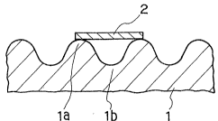
like a bridge, as sehematically sho~n in Fig. 1. In Fi~.
1, reference numerals 1, la and lb indicate a rough paper,
30 the convex portion of the paper and the concave portion of
the paper, respectively. Reference numeral 2 indicates
the colored ink layer transferred. The transferred ink
layer 2 is adhered to the paper at the convex portions la
but the ink layer 2 is out of contact with the paper at
35 the concave portion lb and spans the concave portion lb
like a bridge.
2~57~
By means of the above technique wherein the ink
layer is transferred so that it spans the concave portions
of the receiving medium like a bridge, the transferred ink
image is free of poor edge definition and voids, and clear
5 images can be obtained on a rough paper similarly in the
case of transfer on a smooth receiving surface.
According to the above-mentioned technique
utilizing the ink bridging, it was made possible to
print not only on a smooth receiving paper as in the
10 conventional method but also on such a rough paper as
mentioned abo~7e by means of a thermal transfer printer
which resulted in a further enhancement of utility of the
thermal transfer printer.
In such a situation, a printer capable of
15 printing at a high speed of about 100 cps (corresponding
to a head moving ~elocity of about 260 mm/sec) or more was
recently put to practical use.
In the case of such a high-speed printer, it was
impossible to produce clear images on a rough paper even
20 by using the ink ribbon utilizing the ink bridging and the
usable receiving paper was restricted to a smooth paper.
On the other hand, in the case of thermal
transfer printers, the distance (hereinaf ter re~erred to
as ~ peeling distance") between the position where some
25 portion of the ink ribb~n ;s heated with the heating head
and the position where said heated portion of the ink
ribbon is peeled off from the receiving paper (both
positions are relative ones with respect to the heating
head) or the period of time (hereinafter referred to as
30 " peeling time") between the time when some portion of the
ink ribbon is heated with the heating head and the time
when said heated portion is peeled off from the receiving
paper (hereina~ter, the peeling distance and the peeling
time are generically referred to as ~ peeling condition")
35 varies depending upon kinds of machines. IJnder the
circumstances, there were some cases where an ink ribbon,
which was able to provide clear images in a printer wi-th a
peeling condition, was not able to provide clear images or
- 3 _ 2~77~
absolutely any image in another printer with a dif ferent
peeling condition.
It is an object of the present invention to
provide an ink ribbon Eor thermal transfer printer capable
5 of providing clear images not only on a smooth paper but
also on a rough paper even in a high-speed printing or
even on printers with different peeling conditions.
This and other objects will become apparent from
the description hereinafter.
SUMMARY OF THE INVENTION
The present invention provides an ink ribbon for
thermal transfer printer comprising a foundation and a
thermal transfer layer provided on the foundation,
15 portions of which layer are selectively softened or melted
to be transferred to a receiving medium by selectively
controlling the heat generation of a plurality of heating
elements provided on a heating head)
said thermal transfer layer comprising a colored
Q layer containing a wax-like substance as a main component
of the vehicle thereof, and a thermoplastic adhesive layer
having a film-forming property provided on the surface of
the colored layer,
said thermoplastic adhesive layer having a melt
25 viscosity of 1 x 10 ' to 5 x 10⁶ cP at a temperature by
4 0C higher than the softening temperature o~ the adhesive
layer, a sof tening temperature of 4 5 to 9 0C, a
solidifying temperature of 25 to 65C, and a temperature
difference of at least 10C between said softening
30 temperature and said solidifying temperature.
By the use of the ink ribbon of the present
invention, clear images with no defects such as poor edge
definition and voids can be obtained not only on a smooth
paper but also on a rough paper at printing speeds
3 5 extending between low ones and high ones or under
different peeling çonditions in thermal trans-fer printers.
2 ~ 8 ~
BRIEF DESCRI_TION OF THE DRAWINGS
Fig. 1 is an explanatory view showing the state
where an ink layer is transferred on a rough paper so that
it spans the concave portions of the paper like a bridge.
Fig. 2 is an explanatory view showing changes in
the state of an ink layer heated with a heating head in
the çase of a low-speed printing.
Fig. 3 is an explanatory view showing changes in
the state of an ink layer heated with a heating head in
the case of a high-speed printing.
DETAILED DESCRIPTION
Owing to the thermal transfer layer composed as
mentioned above in accordance with the present invention,
clear images can be obtained not only on a smooth paper
but also on a rough paper at printing speeds over a wide
range from a low speed to a high speed, for example, from
15 cps to 150 cps (corresponding to head moving velocity
of about 40 to about 400 mm/sec), and further on printers
20 with different peeling conditions.
The reason why such ef:~ects are exhibited by the
above construction is not necessarily definite but is
presumed as follows:
In the first placel the transfer mechanism of
25 the colored ink layer in the case that printing is carried
out on a thermal tr~Lns~er printer using a conventional
bridging type ink ribbon wherein a thermal transfer
colored ink layer having a film-forming property is
provided on a foundation.
3 0 Figs. 2 and 3 are explanatory views showing
changes in the state of the ink layer after the ink ribbon
is heated with a heating head. Fig. 2 shows that for a
low-speed printing and Fig. 3 shows that for a high~speed
printing. H indicates a time area where the ink layer is
35 supplied with heat from the heating head and the ordinate
indicates the intensity of the supplied heat energy. A, B
and C indicate the states of the ink layer. A indicates
the state that the ink is in a state of being softened or
2~778~
melted enough and having a property of sticking to a
receiving meidum. B indicates the state that the ink,
which has been once softened or melted, is again
solidifying but is still in a softened state. C indicates
5 the state that the ink i9 in a state of being again
solidified enough.
The investigations of the present inventors have
reveaied the following: When the ink ribbon is peeled off
from the recei~ing paper while the ink layer is at least
10 in state B, for instance, at peeling point Pl, the ink
layer in state B sticks to the receiving paper and peels
off from the foundation of the ink ribbon. However, when
the ink ribbon is peeled off from the receiving paper
while the ink layer is in state C, for instance, at
15 peeling point P2, the ink layer does not peel off from the
foundation, because the adhesive strength between the ink
layer and the foundation is again increased, which results
in failure of transfer.
In the case o-f low-speed printing, the amount of
20 head energy El supplied to the ink layer from the heating
head is large because of a long heating time by means of
the heating head. There~ore, time t 1 that the ink layer
is in state A is sufficiently long and the peeling point
of the ink ribbon falls within the total time Tl of time
25 t~ and time t2 (= tl ~ t2) (hereinafter referred to as
transferaMe time") for usual thermal transfer printers,
which results in a good transfer.
On the other hand, in the case of high-speed
printing, the heating time by means of -the heating head
30 must be reduced but the electric power per unit time input
to the head cannot be increased enowgh in comlection with
the life of the head, etc. Therefore, heat energy E2
supplied to the ink ribbon is smaller than heat energy El
in the case of low-speed printing. This tendency is
35 marked with increasing printing speed.
Accordingly, time t3 that the ink layer is in
state A is shorter than time t 1 in the case of low-speed
printing, and after all transferable time Tz (= t3 + t~ )
~77~
is shorter than time Tl.
In the case of high-speed printing, the peeling
time is shortened because the run speed of the ink ribbon
increases. However, since the peeling distance cannot be
5 so reduced in connection with the mechanism around the
head, peeling point P3 falls within the area that the ink
layer is in state C. Further the period of time that the
ink layer after being melted possesses a property of
sticking to the receiving paper is reduced, which results
10 in an insufficient bonding of the ink to the receiving
paper. For these reasons, poor transfer occurs in the
case of high speed printing.
Even in the case of low-speed printing, there
are some cases that the peeling point lags behind to Pz
15 due to the mechanism around the head of a printer. In
this case, poor transfer occurs even in low-speed printing
because the peeling point P2 is in the area that the ink
layer is in state C.
The function and effect of the present invention
20 are explained.
The thermal transfer layer according to the
present inverltion has a two-layered structure composed of
a colcred layer on the side of the foundation containing a
wax-like substance as a main component of the vehicle and
25 a thermoplastic adhesive layer having a film-forming
property provided on the colored layer.
The adhesive layer has a melt viscosity of
1 x 10~ to 5 x 10⁶ cP (value measured at a temperature by
4 0C higher than the softening temperature), a softening
30 temperature of 45 to gaoC, a solidifying temperature of
25 to 65C9 and a temperature difference of at least
1 0C between the softening temperature and the solidifying
temperature.
Thus the adhesive layer of the present invention
35 possesses a supercooling property as well as film~forming
property.
Herein, the term ~ supercooling property" of the
adhesive layer means the property that in the case that
~0~7~
the adhesive layer is once heated to a temperature above
the softening temperature into a softened state and then
cooled, the adhesive layer is not solidified but in a
supercooled state even when it is cooled to the softening
5 temperature, and the adhesive layer is at last solidified
when it is further cooled to a temperature below the
softening temperature.
The adhesive layer thus composed possesses such
a supercooling property that the adhesive layer which once
10 has been softened by heating with a heating head is not
solidified by a temperature drop during a miximum travel
time required -for the heated portion of the ink ribbon to
travel from the position heated with the heating head to
the peeling position of the ink ribbon from the receiving
15 medium. Herein, when the distance between the position of
the ink ribbon heated wi-th the heating head and the
peeling position of the ink ribbon is taken as ~ d" and
the winding-up velocity of the ink ribbon as UV", the
period of time t requried for the heated portion of the
2 0 ink ribbon to travel from the heated position to the
peeling position is expressed by the equation: t = dJv.
The time t varied depending upon the structural or
operational conditions of a printer. The rnaximum time t
for a printer is referred to as " maximum travel time
25 (t~n~X). The maximum travel time varies depending upon
kinds of machines. Generally, however~ the maximum travel
time for printers put on the market at the presen-t ranges
from about 2 to about 10 milliseconds.
By the use of an adhesive layer having such a
30 supercooling property as mentioned above, time t3 that the
adhesive layer which has been melted or softened enough
retains state A in which the adhesive layer possesses a
strong stickiness to the receiving paper can be widely
extended and the adhesive layer can be in state A or B
35 even at peeling point P3. When the ink ribbon is peeled
off from the receiving paper even in high-speed printing,
the adhesive layer is firmly adhered to the receiving
paper and, therefore, is peeled off from the foundation
2~77~
together with the colored layer containing a wax-like
substance as a main component of the vehicle to transfer
to the receiving medium.
E~en in the case of low-speed printing, time t 1
5 that the adhesive layer retains state A can be widely
extended because of its supercooling propert~. Therefore,
a good transfer can be effected even though the peeling
point lags behind depending upon the peeling condition of
the printer used.
Further, the thermoplastic adhesive layer has a
film-forming property, in a softened state, required to
form clear images on a rough paper. The portion of the
adhesive layer which is once softened shows a fairly
weakened bonding to the adjacent portion which is not
15 heated and softened, and exhibits a strong adhesiveness to
a receiving paper tiIl the softened portion is again
solidified.
The thermoplastic adhesive layer as mentioned
above is favorably transferred to even a rough paper
20 together with the colored layer containing a wax-like
substance as a main vehicle component so that only the
heated portion spans the concave portion of the rough
paper like a bridge because of its film-forming property,
wea~ened bonding to the adjacent portion in a solid state
25 and good adhesiveness to the receiving paper in a softened
state, thereby providing clear images.
Further, in the present invention, the thermal
transfer layer is constructed to have a two layered
structure composed of the colored layer and the film-
30 forming adhesive layer and different roles are assigned tothe respective layers. Accordingly, the film-formi~g
adhesi~7e layer can be prepared to have such an adhesive
formula as to fully exhibit the above-mentioned film-
forming property and supercooling property. Further, the
35 ink ribbon of the present invention has the advantage that
it has a good resistance to rubbing because the adhesive
layer has a great strength.
Thus, the ink ribbon of the present invention
20~77&~
~ 9
can give good images even on a rough paper, complying with
both the changes in peeling condition due to the increased
printing speed and the different peeling conditions for
kinds of machines.
The present invention will be more specifically
explained.
The colored layer in the present invention is
composed of a vehicle containing a wax-like substance as a
main component and a coloring agent.
Examples of the wax-like substance include
natural waxes such as whale wax, bees wax, lanolin,
carnauba wax, candelilla wax, montan wax and ceresine wax;
petroleum waxes such as paraffin wax and microcrystalline
w~x; synthetic waxes such as oxidized wax, ester wax, low
15 molecular weight polyethylene and Fischer-Tropsch wax;
higher fatty acids such as lauric acid, myristic acid,
palmitic acid, stearic acid and behenic acid; higher
aliphatic alcohols such as stearyl alcohol and behenyl
alcohol; esters such as sucrose fatty acid esters,
2 0 sorbitan fatty acid esters; and amides such as oleic
amide. These wax-like substances may be used singly or in
admixture. Preferred wax-like substances have a melting
point of 40 to 120C, particularly 65 to 85C (value
meausred at a temperature rising rate of 10C /min on DSC,
25 hereinater the same). When the melting point of the wax-
like substance is lower than the above range, the melting
point of the colored layer becomes too low, which results
in poor storage stability of the resulting ink ribbon.
When the melting point is higher than the above range, the
30 transfer sensitivty tends to be decreased.
It is preferable to use a thermoplastic resin in
addition to the wax-like substane as a vehicle component
for the colored layer, thereby adjusting the adhesiveness
of the colored layer to the foundation. Examples of such
35 thermoplastic resins include ethylene-vinyl acetate
copolymer, ethylene-alkyl (meth)acrylate copolymers,
polyolefin resins, polyvinyl alcohol, vinyl acetate
resins, styrene-alkyl (meth)acrylate copolymers, styrene
~0~78~
-- 10
resins, saturated polyesters, ancl further synthetic
rubber~like resins such as polybutene, styrene-butadiene
rubber and acrylonitrile-butadiene rubber. These
thermoplastic resins may be used singly or in admixture.
5 From the viewpoint of tranfer sensitivity, the resins
preferably have a softening temperature o 45 to 100C,
particularly 5 0 to 7 5C (the value meausred by TMA
method, hereinafter the same). The thermoplastic resin is
preferably used in an amount of 5 to 50 parts by weight,
particularly 10 to 25 parts by weight per 100 parts by
weight of the wax-like substance. When the amount of the
thermoplastic resin is lower than the above range, the
transfer layer is liable to peel off from the foundation
under normal conditions. When the amount of the
thermoplastic resin is more than the above range, an
uneven tranfer tends to occur, resulting in the formation
of poor edge definition or voids in print images.
As the coloring agent for the colored layer,
there can be used any coloring agent used conventionally
in ink ribbons of this type, incIuding carbon black, and
a variety of organic and inorganic coloring pigments and
dyes. The coloring agent is suitably used in an amount of
5 to 80 parts by weight, particularly 15 to 50 parts by
weight per 100 parts of the wa~-like substance.
2 5 If necessary, a variety of surface active agents
or oils acting as pigm.ent dispersing agent, dispersion
stabilizing agent, flowability con~rolling agent, or the
like may be incorpor ated into the colored layer. Further
other aclditives such as antioxidant may b~ incorporated.
Preferably the colored layer has a melting or
softening temperature of 50 to 9QC, particularly 65
to 75C, and a melt viscosity of 5 x 10 to 5 ~ 103 CP,
particularly 1 x 10² to 1 x 10³ CP at a temperature by
4 0 C higher than the melting or softening temperature (the
value measured by means of a viscoelasticity measuring and
analyzing apparatus MR-300 made by Rheology Co., Ltd.,
hereinafter the same), from the viewpoint of securing a
desi-red transfer sensitivity of the ink and a desirecl
2~77~
transfer amount of the ink. When the melting or softening
temperature is lower than the above range, the resulting
ink ribbon is poor in storage stability. When the melting
or softening temperatue is more than the above range, the
5 transfer sensitivity tends to be lowered. When the melt
viscosity is lower than the above range, the transferred
ink largely spread exceeding the size of the dot of the
heating head when heat is accumulated in the heating head
and clear images are hardly obtained. When the melt
10 viscosity is more than the above range, an uneven transfer
is liable to occur, resulting in the occurrence of poor
edge definition or voids in print images.
The film-forming thermoplastic adhesive layer in
the present invention has a melt viscosity of 1 x 10 4 to
15 5 x 10⁶ cP, particularly 3 x 1~ to 2 x 10⁶ cP at a
temperature by 4 O~C higher than the softening temperature
of the adhesive layer, a softening temperature of 4 5 to
90C, particularly 55 to 75C ~the value measured at a
temperature rising rate of 10C /min on DSC, hereinafter
20 the same), a solidifying temperature of 25 to 65C,
particularly 30 to 50C (the value measured at a
temperature falling rate of 10C /min on DSC, hereinafter
the same), and a temperature difference of not less than
10 C, particularly from 10 to 4 0C, more particularly
25 from 15 to 30C between the softening temperature and
the solidifyirlg temperature. Such an adhesive layer
possesses good film forming property and supercooling
property with retaining good transfer sensitivity and
storage stability.
3û When the melt viscosity of the adhesive layer is
lower than the above range9 the property of transferring
to a rough paper like a bridge becomes poor due to a poor
film-forming property. When the melt viscosity is more
than the above range, an uneven transfer occurs. In
both cases, poor edge definition or voids are liable to
occur in print images. YVhen the softening temperature is
lower than the above range, the s torage stability of the
ink ribbon is poor. When the sof-tening temper ature is
~77~
12
more than the above range, the transfer sensitivity is
poor. When the solidifying temperature i5 less than the
above range, the smearing of the receiving paper is liable
to occur after printing. When the solidifying temperature
is more than the above range, an uneven transfer occurs.
When the temperature difference between the softening
temperature and solidifying temperature is less than the
above range~ the supercooling property is poor, which
results in failure to comply with the high-speed printer
and the different peeling condition.
The adhesive layer is preferably composed o-f a
thermoplastic material having both a film-forming property
and a supercooling property and a thermoplastic material
having an affinity to the above-mentioned colored layer.
The phenomenon that in transfer printing, the
adhesvie layer is separated from the colored layer and the
adhesive layer alone is transferred is prevented by
incorporating a thermoplastic material having an affinity
to the colored layer into the adhesive layer.
The thermoplastic material haYing both a film-
forming property and a supercooling property (hereinafter
referred to as u thermoplastic material AJ9) is
thermoplastic resins such as polycaprolactones, polyamides
(JP, A, 62-37392) and uns~turated polyesters (JP, ~, 62-
35~84).
Polycaprolactones are preferred because of their
good film-forming property and supercooling property.
Preferable polycaprolactones are those ha~ing a number
average molecular weight of 8 x 10³ to 1 x 10⁵, a
30 softening temperature of 50 to 65C, a melt viscosity of
1 x 10⁵ to 5 x 10⁶ cP at a temperature by 40C higher than
the softening temperature, a solidifying temperature of
25 to 40C and a temperature difference of 15 to 35C
between the softening temperature and the solidifying
35 temperature.
Such polycaprolactones have a good film-forming
property because of their great cohesi~e force in a
softened state and also a good supercooling property.
2~7780
-- 13
The ollowing effects are exhibited by composing
the adhesive layer of thermoplastic material A having good
film-forming property and supercooling property. The
image forming ability to a rough paper is good because the
5 bridge-like transfer is favorably effected due to said
film-forming property and therefore clear images can be
formed even on a rough paper. The portion of the adhesive
layer which is attached to the surface of a receiving
paper can retain its softened state for a long time due to
10 said supercooling property. Therefore, the time till the
adhesiveness of the transfer layer to the receiving paper
is lowered or lost can be deferred as compared with the
conventional ink ribbon. For this reason, it is possible
to form clear images in a high-speed printer or a variety
15 of printers with different peeling conditions. For
example, it is possible to print very thin lines with a
width of 0.05 mm without any poor edge definition or void
even on a very rough paper having a Bekk smoothness of
about 20 seconds, regardless of the printing speed or the
20 peeling condition.
With respect to the thermoplastic material
having an affinity to the colored layer (hereinafter
referred to as " thermoplastic material B"), there are
preferably used those which are compatible with
25 thermoplastic material A and also with the vehicle of the
colored layer. Generally wax-like substances are
preferred.
By incorporation of a wax-like substance into
the adhesive layer, a good adhesive condition between the
3 0 adhesive layer and the colored layer is kept during
transfer and the colored layer is transferred in the same
shape as that of the adhesive layer transferred, thereby
preventing the formation of poor edge definition in print
image due to the poor edge definition o f the colored
35 layer.
Wax-like substances similar to those used in the
colored layer are used in the adhesive layer. A
thermoplastic resin can be used in combination with the
7 7 8 ~
wax-like subst~ce as thermoplastic material B.
Thermoplastic resins similar to those used in the colored
laSrer can be used as such a thermoplastic resin for the
adhesive layer. By the incorporation of the thermoplastic
5 resin, the adhesiveness of the adhesive layer to a rough
paper is further improved, so that the print image formed
on a rough paper is completely prevented from peeling of f
from the paper and a transfer with a lesser amount of
energy is made possible. When the thermoplas tic resin is
10 used in combination with the wax-like substance, the
amount of the thermoplastic resin is preferably from about
0. 5 to about 2 0 parts by weight per 10 parts by weight of
the wax-like substance.
Preferably thermoplastic material B has a
15 melting or softening temperature of 50 to 90C,
particularly 55 to 75C from the viewpoint of transfer
sensitivity or the like.
Thermoplastic material B is preferably used in
an amount of 1 to 9 0 parts by weight, particularly 2 to 5 0
2 0 parts by weight per 10 parts by weight of thermoplastic
material A. When the amount of thermoplastic rnaterial B
is less than the above range, the adhesiveness of the
adhesive layer to the colored layer is poor and the efect
of enhancing the adhesiveness to the receiving paper is
2 5 not developed. When -the amount of thermoplastic material
B is more than the above range, the film-forming property
and supercooling property are poor.
Into the adhesive layer, there may be
incorporated other additives in addition to the above
3û mentioned components without spoiling the object of the
present invention. E~amples of the additives include
antioxidant (e.g. phenol derivative antioxidants such as
monophenol derivative, bisphenol derivative and
polymerized phenol derivatives), and heat resistance
35 improving agent used for preventing blocking occurring
between the adhesive layer and the rear surface of the ink
ribbon during storage of the ink ribbon in the form of a
roll or pancake at elevated temperatures (e.g. body
- 15 ~ ; 7 7 ~3 ~
pigments such as silica and titanium oxide, carbon black
and organic pigments such as phthalocyanine blue~ fine
particles of thermosetting resins such as formaldehyde
resin, phenol resin ahd amino resin).
5In the present invention, a substantially
transparent thermal transfer layer containing
substantially no coloring agents may be interposed between
the colored layer and the foundation. When such a
transparent transfer layer is provided in the ink ribbon,
10 the corresponding transparent layer containing no coloring
agents necessarily exists on the surface of the obtained
print image. Accordingly, even when the surface of the
image is rubbed with an article, there is no possibility
that the coloring agent, such as pigment, contained in the
15 colored layer is attached to the article. Further, no
problem occurs that the coloring agent is trans:~erred to
portions of the receiving paper where no print images are
formed to smear the receiving pap~r.
The transparent transfer layer is preferably
2 0 composed of a wax-like substance to obtain a good heat
melt transferability and an affinity to the colored layer.
The same wax-like substances as used in the colored layer
are used as the wax-like substance. The preferred i9 one
or mixtures of paraffin wax, polyethylene wax, candelilla
25 wax, ester wax, carnauba wax, and the like. Into the
transparent transfer layer, there may be further
incorporated a thermoplastic resin which is the same as
used in the colored layer, or other adhesive material, in
order to control the adhesi~eness. The transparent
30 tr~nsfer layer preferably has a melting point of 65 to
80C
Other additives such as dispersi:ng agent,
antioxidant, oil for viscosity control, and surface active
agent may be appropriately incorporated into the
35 transparent transfer layer.
A variety of plastic films generally used as a
foundation film for this type of ink ribbon, including
polyester film, polyamide film and others can be used as a
20~7~
foundation in the present invention. In the case of using
such plastic films, it is suitable to provide on the rear
surface of the foundation (the surface in sliding contact
with the heating head) a conventional stick pre~renting
5 layer composed of silicone resin, fluorine-containing
resin or nitrocellulose, or mixtures of the foregoing
resins with lubricating materials, in order to prevent the
foundation from sticking to the heating head. High
density thin papers such as condenser paper can also be
10 used as the foundation. The thickness of the fouxldation
is preferably from 1 to 9 ,u m, more preferably from 2 to
4.5 ,u m in order to obtain a good heat conduction.
The ink ribbon of the present invention can be
produced by optionally forming a transparent transfer
layer by solvent coating method or hot melt coating
method, forming a colored layer thereon by solvent coating
method or hot melt coating method, and forming an adhesive
layer thereon by solYent coating method. The thickness
of the colored layer is preferably from 0.5 to 10 ~ m,
more preferably 1 to 5 ,u m. The thiclsness of the adhesive
layer is preferably from 0.3 to 5,u m, more preferably 0.5
to 2.5 ,u m. The thickness of the transparent tranfer
layer is preferably from 0.1 to 5 ,u m, more preferahly
from 0.5 to 3 ,u rn.
In the present invention! either a thermal
transfer layer with single color may be formed on single
foundation, or a plurality of thermal transfer layers with
different colors (e.g. yellow, cyan and magenta, and
optionally black) may be formed on single foundation in a
30 side-b~side relationship.
In the case of printing using the ink ribbon of
the present invent~on, clear images can be formed on any
paper so long as it has a E3ekk smoothness of not less than
about 10 seconds, regardless of kinds of paper, e.g. bond
35 paper1 paper for PPC and paper for thermal transfer. Of
course, clear images can be obtained on smooth plastic
films.
The present invention is more speci Eically
2~77~
- 17
described and explained by means of the following
Examples. It is to be understood that the present
invention is not limited to the Examples, and various
change and modifications may be made in the invention
5 without departing from the spirit and scope thereof.
Examples 1 to 5 and Comparative Example 1
Onto the front surface of polyethylene
terephthalate ~ilm having a thickness of 3.5 ,u m pro~ided
10 with a stick-preventing layer having a thickness of 0.2,u m
composed of silicone resin on the rear surface thereof was
applied the composition shown in Table 1 by solvent
coating and dried to give a colored layer having the
physical properties shown in Table 1.
Each composition shown in Table 2 was applied
onto the colored layer by solverlt coating and dried to
give an adhesive layer having the physical properties
shown in Table 2. In the case of Example 5, the
composition shown in Table 3 was applied onto the above
2 0 polyethylene terephthalate film by solvent coating and
dried to giYe a transparent transfer l~yer having the
physical properties shown in Table 3, followed by the
successive formation of the colored layer and the adhesiv
layer.
%~7~
-- 18
~ ~ o
2~57~g~
-- 19
_ ~ ~ ~ o
~7 ~ CD ~ O ~ X
~ . o~
~ ~ - O ~,^ Ov^
, o
O ~ ~¢ .
o
C`~ C~ ¢ CQ C~ Lt~ ~ oV ~ o ~ d ~
c~ ~ o o LL~ ~ - X ~3 o
~ O _ ~ ,o ~ t~
_ o ~ ~
¢ ~ ~ ~ O ~ ~ ~
,~ O o ~ ~ D ~
O~ ~ ~ ~ ~ b y :~! b y a ~
e-- ~ ~Ov oO
o ~, ~ D ~ D e S3 ~ S
20~77~
~ 20
~,
U~ ~
20~77~
-- 21
Employing each of the ink ribbons obtained
above, printing tests were conducted on the thermal
transfer printers mantioned below under the conditions
shown in Table 4.
Low-speed printer: WD-652 (30 cps) made by Sharp
Corporation
Medium-speed printer: Ul Pro 501 ~45 cps) made by
lû Matsushita Electric Industrial Co.,
Ltd.
High-speed printer: Ul Pro 503 AI (75 cps) made by
Matsushita Electric Industrial Co.,
1 5 Ltd.
The number of dots per one character was 4 8 for
every printer. Paper for thermal transfer (Bel~k
smoothness: 600 seconds), paper for PPC (Bekk smoothness:
2 0 5 0 seconds) and bond paper (Bekk s~r.oothness: 10 seconds)
were used as the receiving paper.
The clearness and the void or poor edge
definition were e~a~uated with -the images obtained on the
receiving paper according to the evaluation method
25 mentioned below. The results thereof are shown in Table
5.
A. Clearness
One dot printing was carried out. The ratio of
3 0 the area of one dot of the ink actually printed to the
area of one dot, i. e. one heating element, of the heatillg
head was determined. The obtained values were graded into
five classes as mentioned below.
35 5 - Area ratio: 0.95 to 1.05
4 Area ratio: not less than 0.85, less than 0.95
3 Area ratio: not less than 0.75, less than 0.85
2 Area ratio: not less than 0.55, less than 0.75
2~778~
-- 22
Area ratio: less than 0.55
B. Yoid or poor edge definition
Solid-printing was carried out. The optical
5 density (OD value) of the printed paper was measured at
the predetermined fi~e positions and the average ~alue was
obtained. The values were graded into five classes as
mentioned belowO
10 5 - OD value: ;not less than 1.5
4 OD value: not less than 1.2, less than 1.5
3 OD value: not less than 0.9, less than 1.2
2 - OD value: not less than 0.6, less than 0.9
1 OD value: less than 0.6
2~77~
~ 23
~ o
.
~ ) ~
a~ G ~ ~
2~77~
-- 24
1¢
.~ 1~ oL~ L~
P
I ~
I¢
LC~L~LO Lf~L~L~
L ~ ~ ~
~ c~ a:~ Lt~ er ct~ L~ ~ ~ Lt~
¢ L~ L~ LO ~ c~
LO L~ ~r L~
1~ Ll~L~ L~L~r L~Lt~
~ ~ ~
.~ o o ~ ~o o ~ ~ o ~
~ h ~
~o ~ ~ o.
v~ 3 ~ . ;z; ~ ~
~0~77~
-- 25
As is clear from the results shown in Table 5,
Examples 1 and 5 provided a high quality of images with no
void and no poor edge definition not only on the smooth
paper but also on the bond paper at every one of low
5 speed, medium speed and high speed.
Examples 2 to 4 provided almost satisfactory
results, which were a little inferior to those obtained in
Examples 1 and 5.
In contrast thereto, the images obtained in
10 Comparative Example 1 were poor in clearness and contained
remarkable voids and poor edge definition. Poor results
were obtained especially in the case of the high-speed
printing or the printing on the bond paper.
With respect to Example 5, even though the
15 images on the receiving paper were rubbed with another
receiving paper, it was not stained. Further, any stain
did not occur which was caused due to the phenomenon that
the coloring agent contained in the print image was
transferred to portions of the receiving paper where no
20 images were formed.
In addition to the materials and i ngredients
used in the Examples, other materials and ingredients can
be used in the Examples as set forth in the specification
to obtain substantially the same results.