Note: Descriptions are shown in the official language in which they were submitted.
2~72~5~
Co~re Orientation Device
The present invention is concerned with the taking of core samples of
underground strata and is a device to enable the determination of the
angular orientation of a core sample.
The practice of taking core samples for the purpose of identi~ying and
analyzing the orientation and thickness of underground rock and sirnilar
strata is well established. Apparatus used for this purpose usually entails a
rotating, hollow cylindrical cutting bit which cuts a continuous or
discontinuous cylindrical core sample and feeds the core sample into a
non-rota~ing inner tube or core tube. The core tube is subsequently
withdrawn, either. with the drill string or at the end of a cable or "wire
line", and brings the core sample within it.
In order to interpret the information given by the core sample it is
necessary not only to know the directiorl of inclination of the borehole
relative to the vertical but also to understand how the strata under
investigation are orientated relative to the axis of the borehole.
Conventionally the latter feature is determined by drilling further
boreholes, spaced from the first one, and repeating the core sarnpling
exercise for each borehole. Such additional boreholes each represents a
significant expense.
An alternative to the drilling of additional boreholes is to establish the
rotational angular orientation of the core sample within a given borehole.
In view of the considerable expense which is potentially to be saved in this
way, many attempts have been made to determine this core orientation;
using a variety of methods. For example" it has been proposed to scribe a
line on the core itself while the sample is being taken and to hold the drill
pipe without turning while it is being lowered into a borehole. However it
is difficult to prevent the drill pipe twisting and also the core tube may
..- . ~ ~ .
,
. :, - ~ . , :.; , ' .; -~,
-2- 2~722~3
turn relative to the drill pipe while the latter is being lowered. Thus the
results obtainable by this difficult procedure are scarcely reliable.
Another method of attempting to determine the orientation of the core
tube and core relative to the drill pipe is to lower into the drill pipe a
device which takes an impression of the base of the borehole and then to
attempt to match that impression to the face of the core sample. This
determination not only involves non-productive time for the drilling rig but
again takes no account of possible twisting of the drill pipe. When one
recognises also that the surface of whic:h the impression is to be taken may
be caved-in or formed of silt, the unreliability of such prior art methods is
immediately apparent.
It is therefore an object of the present invention to provide a device
for determining the angular orientation of a sore sample relative to the
axis of a borehole, whereby at least same of the disadvantages of prior
lS methods of carrying out this determination are reduced or eliminated.
The core orientation device according to one aspest of the present
invention comprises an elongated, generally cylindrical housing, attachment
means to connect the lower end of said housing, to the upper end of the
inner tube of a core sampling device, an elongated body adapted for linear
axial movement within said housing between a retracted position nearer to
the upper end of said housing and an orientation indicating position nearer
to the lower end of said housing, retention means to releasably retain said
elongated body in said retracted position, a trigger device, adapted to pass
down the associated drill string and to cause said retention means to
release said elongated body, a multiplicity of apertures in the lower end of
said generally cylindrical housing and disposed substantially uniformly
around the axial centre of said housing end, and an indicator, mounted
upon said elongated body ~or movement a~ound the axis theïeof in
response to gravity and adapted to remain above said housing end when
the body is in its retracted position and to engage one of said apertures
when the body is in its orientation indicating position.
'
: ::
,
2~722Q3
- 3 -
In use, the core orientation device of the invention is attached to the
inner tube of the core sampler and remains there during the core
sampling. When the sample has been drilled, the device is activated by
dropping or lowering the trigger device down the bore hole and the
S elongated body is thereby released so that it may move from its retracted
to its orientation indicating position, in which the indicator, having adopted
a position in response to gravity, engages one of the apertures in the end
of the housing and thereby indicates the orientation of the core tube
relative to the axis of the borehole. It is a significant feature of the device
according to the present invention that the indicator, when subsequently
withdrawn with the core tube, gives a direct indication of the orientation of
the core sample last taken and can therefore be relied upon, since there is
no significant operation bet veen the core sampling and the activation of
the indicator device during which disorientation of the sample could occur.
The generally cylindrical housing within which the elongated body is
movable may very conveniently be of the same diameter, or approximately
so, as the diameter of the inner tube or core tube of the core sampler. To
accommodate the cylindrical housing, an outer housing, of the same
external dimensions as the outer tube of the core sampler, may be
interposed and secured in position between the outer tube and the drill
string, whereby the rotating drive to the cutter bit is transmitted from the
drill string. The generally cylindrical housing is attached at its lower end to
the upper end of the core tube, such that the housing and core tube
remain stationary together or rotate together, independently of the drill
string. ~he attachment means may simply be a transverse pin, which may
extend through a suitable cylindrical socket on the housing and into or
through the spindle of the core tube.
Within the housing, the elongated body is retained for movement
between its retracted upper position and its lower position in which it
indicates the orientation of the core sample. The body may be releasably
retained in its retracted position by one of various possible retention
': - " ' '; ' ~ '
4 2~22~3
means. For example, a ball or other sprung latch within a radial bore in
the elongated body may normally, under the spring pressure, engage a
suitable socket in the irmer tube of the housing, such that the elongated
body may be released by sufficient axial pressure to overcome the spring.
S In another form of the invention the retention means comprises one or
more latches, which engage the housing in the region of its upper edge and
nay be disengaged by radially inward pressure on the latch(es).
The nature of the trigger device depends, at least to some extent, on
the form of the aforementioned retention. Thus, when the retention means
takes the form of a sprung latch releasable by axial pressure on the
housing, then the trigger device may be a, preferably solid, body, which
may be dropped or lowered down the borehole past the fluid contents of
the borehole and release the elongated body by striking its upper end. In
another form of the invention in which the retention means comprises
latches engaging the upper end of the housing, the trigger device may be a
hollow cylinder which may be dropped or lowered into a position in which
it surrounds the latches and disengages them from the housing by urging
them radially inwardly.
At the lower end of the housing, a multiplicity of apertures are
disposed substantially uniformly around the axial centre of the housing.
The apertures may be discrete holes through the end of the housing or
they may be radially elongated slots, which may in turn be discrete or may
be interconnected at the aforementioned axial centre. Since the function of
the aper~ures is each to provide a position for potential engagement by the
indicator (depending upon the orientation of the core tube), they are
preferably disposed at equal angular intervals around the centre. The
accuracy of the determination is determined to a substantial extent by the
number of apertures, so preferably there are a large number of such
apertures, for example between 20 and 30 such apertures (at angular
intervals of 18 to 12 degrees of arc) or more.
: ~ ... , .. ,.... . , j,
~ ~'
~ . . :
~7~2~
- 5 -
At the lower end of the elongated body, the indicator is mounted in
such a way that it can adopt a position relative to the axis of the body
which is in response to gravitational force. The core orientation device
according to the invention is used in inclined boreholes so the position
adopted by the indicator will reflect the direction of inclination of the
borehole. That is, the indicator will adopt a position in which it (or at least
its centre of gravity) will lie below the axis of the borehole. To achieve this
result, the indicator may take the form of a weighted pointer, mounted for
rotation about the axis of the elongated body and with its centre of gravity
eccentric to that axis. In another form, the indicator may be a pointer,
mounted with one end on a universal joint at the bottom end of the
elongated body, such that it swings rather lilce a pendulum below the body.
It will be apparent that the indicator, which adopts a position reflecting
the direceion of inclination of the borehole while the elongated body is
retracted, is simultaneously indicating the rotational position of the core
tube relative to the axis of the borehole. Thus, when the elongated body is
released to enable it to enter its lower position, the indicator is
immobilised by engaging one of the apertures and thus the core
orientation is indicated in a manner which will not be misdirected by the
withdrawal of the core tube and core sample from the borehole. Further
security may be achieved by providing for the elongated body to become
retained in its indicating position until after the core sample has be~n
removed. For example, a spring latch or the like may become engaged
aueomatically when the body moves into that position. Alternatively or in
addition, the body may be urged into its indicating position by a spring, for
example a coil spring, acting between the elongated body and the
cylindrical housing.
In accordance with a further aspect of the invention there is provided a
device to enable the determination of the angular orientation of a core
sample, which device comprises an elongated, generally cylindrical housing
", :,; ' .: ' '~
- ~ ,, 7
2~22~3
- 6 -
defining a longitudinal axis, attachment means to connect the lower end of
said housing to the upper end of the inner tube of a core sampling device,
a body adapted for linear axial movement within said housing between a
retracted position nearer to the upper end of said housing and an
S orientation indicating position nearer to the lower end of said housing,
means tending to retain said body in the retracted position, means for
transmitting forces to said retaining means to enable the body to be moved
to the orientation indicating position, said means for transmitting forces
being adapted to co-operate with an activating means which in use is
passed by gravity along the drill string into engagement with the means for
transmitting forces to cause the body to move to the orientation indicating
position, a multiplicity of apertures in the lower end of said generally
cylindrical housing and disposed substantially uniformly around the axial
centre of said housing end, and an indicator mounted upon said body
within said housing for movement around the axis thereof in response to
gravity and adapted to remain above said housing lower end when the
body is in its retracted position and to engage one of said apertures when
the body is in its orientation indicating position.
Other optional features of the core orientation device according to the
present invention, and the advantages obtainable by means of that device,
will become apparent from the following description with reference to the
accompanying drawings. The drawings illustrate, by way of example, three
preferred embodiments of the device. In the drawings:-
Fig. 1 is a schematic longitudinal sectional view of
the first embodiment of the core orientation device,
with the elongated body in the retracted position;
Fig. 2 is a view corresponding to Fig. 1 with the
elongated body in the core orientation-indicating
position;
. . i . .. .. . . .......... . .... . .
~-
:
7 2~72~
Fig. 3 is a schematic transverse sectional view of the
lower end of the generally cylindrical housing for that
body;
Fig. 4 is a longitudinal section view of a second
embodiment of the invention;
Fig. 5 is a longitudinal section view of a third
embodiment of the invention, non-essential structure
having been omitted; and
Fig. 6 is a longitudinal section view of the upper end of
the embodiment of Fig. 5.
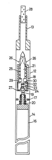
The device is illustrated vertically for the sake of clarity but in practice
the borehole in which the device is used will be inclined to the vertical.
Thus the broken lines 10 and 11 indicate the true horizontal and vertical
respectively.
The illustrated device is contained in an outer tubular housing 12
which is interposed between the lower end of the d~ill string 13 and the
upper end of the outer tube 14 of the core sampler. Thus the tube 14
rotates with the drill string in the usual way and cuts a generally cylindrical
core sample 15, which is taken up in conventional manner into the sampler
inner tube 16. The inner tube 16 is supported in bearings 17 and normally
remains stationary while the outer tube 14 rotates.
The core orientation device comprises a generally cylindrical housing
18, secured by a diametrical pin 19 to the spindle 20 of the inner tube or
core tube 16, so that the housing 18 rotates only if the core tube rotates.
Within the housing 18 is an elongated body 21 which, subject to the effect
of further features referred to below, is free to move a short axial distance
in the housing. Upon a downward axial extension 22 of the body 21, an
eccentrically mounted indicator ~3 is free to rotate. The indicator 23
carries a needle 24 which, by virtue of the rotation of the indicator under
the influence of gravity towards its lowest position, always indicates the
position of the lowest side of the body 21 and
,
,
- -
- , . . , : . ~
- 8 - 2~22~3
of the core tube 16 to which that body is attached.
A compression spring 25 urges the body 21 downwardly within the
housing 18 but the body in imtially retained a~ainst the spring pressure by
a pair of radially outwardly sprung latches 26, which are pivoted at the
S upper end of the body 21 and engage the adjacent end of the housing 18.
The lower end of the housing 18 has a ring 27 of numerous countersunk
circular apertures (see Fig. 3), each of which apertures is of a sufflcient
diameter to receive at least the tip of the needle 24. Ihe dimensions of the
body 21 are such that, when the body is held in its retracted position
illustrated. in Fig. 1, the tip of the needle 24 is spaced by a short distance
above the ring of apertures 27.
In use of the core orientation device, when a core sampling run has
been completed, an elongated tubular trigger 28 is dropped or lowered
down the drill string. The trigger 28 is able to pass over the latches 26 and
press them radially inwardly, so that they may adopt the position
illustrated in Fig. 2. Release of the latches in this way allows the body 21
to move downwardly under the in~luence of the spring 25 until a shoulder
29 on the body is stopped by an annular landing seat 30 on the housing 18.
Movement of the body 21 in this way allows the needle 24 to enter the
angularly nearest of the aperhlres in the ring 27 and to project out through
the end of the housing 18. Thus when the core sampler and the orientation
-indicator are subsequently withdrawn from the borehole to enable the core
ample to be analyzed, the needle 24 gives an irnmediate visual indication
of whic~ side of the sample was rotationally lowest in the underground
location from which the sample was taken.
The second embodiment of the core orientation device according to
the invention, which is illustrated in Fig. 4 of the accompanying drawings,
comprises a short elongated body 40, mounted in a top member 41 for
limited axial movement within a generally cylindrical housing 42. A bottom
member 43 closes the lower end of the housing 42 and connects the
: .
~' ' ~..................... . : ~ -
- ' ,':
2~722~3
housing in use, by means of a pin inserted in a bore 44 in the bottom
member, to the upper end of a core sampler inner tube (not shown).
The body 40 is illustrated in its retracted, upper position in Fig. 4. It is
retained in that position by a pair of latches 45, which engage the upper
S end of the top member 41. The body 4ID may be released from the
retracted position by means of a tubular trigger 46, which is dropped or
lowered down the drill string and thus encircles the latches 45 and urges
them inwardly towards the axis of the dlevice.
A pendulum 47 is suspended by a universal joint 48 from the lower
end of the body 40 and is free to adopt any orientation within the housing
42. In practice, since the device is used in a location within an inclined
borehole, the pendulum will invariably be inclined in use (relative to the
axis of the housing) towards the lowest point of the housing circumference.
The housing bottom member 43 has in its flat face towards the
lS pendulum a ring of apertures 49. There are 36 such apertures, uniformly
spaced at angular intervals of 10 degrees of arc. When the latches 45 are
released by the trigger 46, the body 40 is urged downwardly by a spring 50
and a pin 51 on the end of the pendulum 47 enters the nearest of the
apertures 49, thus indicating the direction of relative inclination of the
pendulum 47 and housing 42 at that instant. The pin 51 remains in the
relevant aperture 49, under pressure from the spring 5Q while the device
and core sample are being withdrawn from the borehole.
A third embodirnent of the invention is shown in Figs. 5 and 6. The
structure is simple and accidental actuation of the apparatus is unlikely.
The lower end of the structure shown in Fig. 5 corresponds to the lower
end of the Fig. 4 embodiment as far as the housing 42, bottom member 43,
pendulum 47, universal joint 48, apertures 49, spring 50 and pin 51 are
concerned. The main differences reside in the means for retaining the
body 40 in the retracted position with pin 50 clear of the apertures 49, and
for moving the body 40 into the orientation indicating position.
.
-, ~ , . . - .
' " ' ' ' ' ' "' : : ' : ... ' .' ' '
- lO- 2~72~.03
As seen in Fig. 5, the upper end of body 40 is attached by element 60
and transverse pins 62, 64 to an elongated main thrust rod 66 which
extends upwardly within the latch housing 68 (details of which are omitted
here). The upper end of latch housing 68 has an arrow-head 70 fixed to it
S and which is adapted to be engaged by the jaws of a standard overshot 72
in the well-known position. The body of the arrow head 70 has a pair of
axially aligned bores 74, 76 therein, the larger bore 74 containing a coil
compression spring 78 which bears against a plate 79 fixed to the lower
end of a second thrust rod 80 which extends freely through the second
bore 76 and projects above the upper end of arrow head 70. The plate 79
bears against the upper end of thrust rod 66.
The body 40 is normally retained in the retracted position by the
upward thrust of coil compression spring 82 which interacts between the
lower face of body 40 and a ring seat 84 on the interior of housing 42.
Spring 82 is much stronger than spring 78 and hence spring 78 mainly
serves to keep the plate 79 firrnly in contact with the upper end of thrust
rod 66 at all times.
In operation, when it comes time to pull the core sample upwardly, the
overshot 72 is dropped down the bore and approaches the upper end of
arrow-head 70. The overshot 72 is conventional except that it is provided
with a small landing 86 adapted to engage the upper end of the second
thrust rod 80. Hence as the overshot 72 moves downwardly and latches on
to the arrow head 70, it pushes thrust rod 80 downwardly which in turn
forces thrust rod 66 and body 40 downwardly along with the gravity-
oriented pendulum 47 whereupon the pin or needle 51 enters an adjacent
aperture 49 to provide an indication of angular orientation as previously
descnbed.
- While the il~vention has been exemplified by three particular
embodiments illustrated in the drawings, the core orientation device
according to the invention is suitable for use with a wide variety of core
' ; ' . ~ . . ~ ~ ` - .
. . '~ , ' ' . , . ~ . ,
., - ,, . ~ :
" . . ~ , , .
- 11 2~72~
sampling systems, including wire line systems, if necessary after
modification of the core barrel backend.
- ~ . . , ............... ~ ,, . . -- .
., ~ - . , , .; . ..
- . . .- . ,......... . : . , . ~ ,. -