Note: Descriptions are shown in the official language in which they were submitted.
20872~
-
Re~toration Kit For Communications Cable
Technical Field
This invention relates to a restoration kit for communications
5 cable.
Back~round of the Invention
The use of communication cables which include a plurality of
optical fibers is rapidly expanding. An optical fiber cable may comprise a
plurality of glass fibers each of which is protected by at least one layer of a
10 coating material. The optical fibers may be assembled into units in which
the fibers are held together by binder ribbons to provide a core. In one
manufacturer's line of cables, the core is enclosed by a plastic tube and a
plastic jacket.
During the service life of an optical fiber cable, the cable may
15 become damaged. This may occur, for example, through unintentional
contact by various kinds of excavation equipment, by lightning or by
repeated attacks by animals such as gophers. Such damage may be partial,
in which case one or several optical fibers may be interrupted, or the
damage may be total, such as a complete cable cut, for example.
In any case, it becomes necessary to restore service as quickly as
possible. This may be done through an expedited temporary arrangement
while more work is under way to replace the damaged cable with an
equivalent or enhanced system.
A temporary arrangement must be one which is easily ;nstalled
25 and which is low in cost. Elements of the arrangement must be capable of
being packaged in a carrying case which is portable and, desirably, in one
which may be carried by an individual from a vehicle to a field location at
which a disruption to service has occurred.
Whatever the structure of the damaged cable, there must be
30 provisions for connecting, such as by splicing, transmission media of the
cable on each side of the damage location to corresponding transmission
media of a restoration cable which is used to bridge around the damage
location. It is conventional to use a closure, within which all conductors are
connected, wrapped and stored and protected environmentally.
2087~
-
- 2 -
During the connection of metallic conductors, it is customary to
bend sharply the conductors, to provide access to other connections. The
physical nature of glass optical fibers forecloses the adoption of
connectorization techniques which are used with metallic conductors within
5 a closure. Because of their small size and relative fragility, special
considerations must be given to the handling of optical fibers in closures.
Transmission capabilities may be impaired if an optical fiber is bent
beyond an allowable bending radius, the point at which light no longer is
totally contained in the core of the flber. Furthermore, expected lives of the
10 fibers will be reduced if bent to less than the minimum bending radius.
In the prior art, flber slack normally has been provided adjacent
to connective arrangements. When splicing optical fibers by mechanical
means or by fusion, it becomes necessary to provide enough slack flber so
that the fiber can be pulled out of a closure and positioned in apparatus for
15 the preparation of fiber ends and the joining together of the ends.
As might be expected, flber closures are available in the prior
art. Some of these prior art closures have shortcomings insofar as being used
in a temporary restoration arrangement. See U.S. patent 4,820,007. In it, a
splice tray includes provisions on one side for holding optical flber splices
20 and metallic conductor splices on an opposite side. An electrical bonding
and gripping assembly is adapted to be mounted on the splice tray. The
closure also includes mating cover portions which are moved into
engagement with each other to enclose the tray. Also, a waterblocking
encapsulant may be introduced into the closure.
The prior art also includes an emergency restoration system
which includes a self-contained portable system that is capable of being
stored in a craftsperson's vehicle and carried in a handy carrying case to a
cable damage location. One portion of a damaged optical flber cable is
inserted into one splice case and optical fibers of the cable are terminated in
30 splicing devices therein. Another portion of the damaged cable on an
opposite side of the damage location is terminated in another splice case.
Portions of a temporary cable which is coiled adjacent an outer rim of the
carrying case are uncoiled to span the damage location. Ends of the
temporary cable are term;nated by corresponding ones of the splicing
35 devices in each splice case at each end of the temporary run. The
temporar~ cable has an outer diameter of about 0.5 inch.
20~72q6
--3--
What is needed and what seemingly is not available in the prior art is
a restoration kit for communications cable which kit is packaged in a carrying case
with the weight of the kit and the case being less than about fii~y pounds. The
sought-after kit should be relatively inexpensive and should be capable of being5 deployed rapidly with easy payout of a restoration cable to restore service as quickly
as possible after an outage.
SummarY of the Invention
In accordance with one aspect of the invention there is provided a
restoration kit for providing service around a damage location of a communications
10 cable, said restoration kit comprising a carrying case which includes first and second
portions adapted to be secured together, a mounting platform which is disposed
within said first portion of said carrying case and which includes a recess therein, a
deployment reel which includes two spaced flanges and a hub extending between
said flanges and which is supported on said mounting platform, a first closure which
15 includes connective means disposed therein to facilitate connecting of optical fibers
of optical fiber cables thereto, means for holding said first closure secured with
respect to one of the flanges of said deployment reel, a second closure which issupported on said mounting platform and which includes optical fiber connective
means to facilitate connections between optical fibers characterized by, a length of
20 restoration optical fiber cable which is wound in convolutions on said hub of said
deployment reel, said le~loldlion optical fiber cable having one end portion, the
optical fibers of which are adapted to be connected through connective means in said
first closure to optical fibers of said damaged cable on one side of a damage
location, secured in said first closure and another end portion, the optical fibers of
25 which are adapted to be connected through connective means in said second closure
to optical fibers of the damaged cable on an opposite side of the damage location,
secured in said second closure; and a payout spindle which is supported on said
mounting platform and which is adapted to have an end portion disposed in said
recess in said mounting platform to cause said spindle to be disposed to facilitate the
3 o mounting of said deployment reel on said spindle such that said second closure
together with the other end portion of said length of restoration optical fiber cable
may be moved generally in any radial direction from said spindle in a direction
normal to-an axis of rotation of said reel to a location along the damaged cablewhich is remote from the damage location and at which connective arrangements are
. , ,
~A
2a~7296
--4--
made within said second closure between optical fibers of said restoration cable and
optical fibers of the damaged cable.
Brief DesL ;~tion of the D.~
FIG. 1 is a perspective view of a restoration kit of this invention;
FIG. 2 is a perspective view of a closure, two of which are included
in the restoration kit;
FIG. 3 is an end view of a cable which is included in the restoration
kit of FIG. l;
FIG. 4 is a simplified perspective view of the restoration kit showing
10 the position of a payout spindle and the payout position of a first closure in a
deployment reel closure holder;
FIG. 5 is a detail side elevational view in section of the deployment
reel as it is disposed within a well of a pad in one portion of a carrying case;FIG. 6 is a schematic view which shows the use of the restoration kit
15 to provide service for a total cable failure with no slack;
FIG. 7 is a schematic view which shows the use of the restoration kit
to provide service for a total cable failure with slack;
FIG. 8 is a schematic view which shows the use of a lc~lo~dlion kit to
provide service for a partial cable failure with a taut sheath;
2 0 FIG. 9 is a simplified perspective view of the deployment reel
mounted on the payout spindle;
FIG. 10 is a simplified perspective view of a second closure
positioned to be moved away from the carrying case to a portion of the cable on the
other side of a damage location; and
FIG. 11 is a schematic view of one of the closures of the restoration
kit with a plurality of fibers of the re~lolalion cable being spliced to fibers of the
damaged cable.
Detailed D~s~ tion
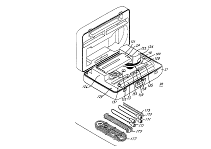
Referring now to FIG. 1 there is shown a restoration kit which is
3 o design~ted generally by the numeral 20 and which is used to provide service around
damage locations in communications cables. The restoration kit 20 includes a
carrying case 21 in which are disposed a first closure 22 and a second closure 23
which is identical to the closure 22. Each closure has a longitudinal axis 26 (see
FIG. 2).
A '
; ~;QJ 72q6
~_ -4a-
Going now to FIG. 2, it can be seen that closure 22 includes a base
24 and a cover 25. The closure 22 may be one such as is described in U.S. PatentNo. 5,189,725 that issued on January 28, 1992. The base 24 has an invert portion28 and sidewalls 29-29. Furthermore the base 24 includes a pad 31 including
5 radiused, longitudinally extending side portions 33-33 and two spaced apart
longitudinally ~xt~n-ling grooves 35-35. Preferably, the pad 31 is made of a foamed
polymeric material. The pad 31 is inserted therein to support two side supports or
pedest~l~ 37-37 between which are adapted to be disposed a plurality of splicingdevice holders or modules 40-40. Each of the modules 40-40 is adapted to hold any
10 one of several different kinds of commercially available connective devices. Such a
module is described in C~n~ n Patent No. 2,057,489 that issued on April 4, 1995.A suit~ble connective device is one described in U.S. Patent No. 5,125,057.
Viewing again FIG. 2, it can be seen that each splicing module 40
includes a plurality of holders 41-41 each of which includes a base 42 and two
sidewalls 43-43. Disposed in each holder 41 is an insert 44 which is adapted to
store a plurality of optical fiber splices which may be made using any of a plurality
of commercially available optical fiber splice arrangements. Each insert is made of
a material such as a foamed polymeric material which is compliant about the
configuration of the particular connective arrangement which is used.
As can be seen in FIG. 2, the insert 44 includes two sidewalls 45-45
between which are disposed a plurality of partitions 46-46. A nest 47 is formed
between each sidewall 45 and the adjacent partition and is formed between adjacent
ones of the partitions. Each nest is adapted to hold a connective device for optical
fibers.
.0~7296
--5 -
Also attached to each end of the base 24 are a plurality of ring
clamps 54-54. Each cable end portion extends through a ring clamp 54 into an inner
portion of the base 24.
Further as can be seen in FIG. 2, the base 24 is provided with
longitudinally extending side portions 56 and 57. The side portion 56 is H-shaped in
cross section with one groove 58 thereof facing toward the cover 25 and one groove
59 thereof facing toward a plane which extends through the invert portion 28. The
side portion 57 includes a rib 61 which faces toward the cover 25 and a groove 62
10 which faces toward the plane of the invert portion 28.
Viewing again FIG. 2, it is seen that the cover 25 also is U-shaped,
having a center portion 54 and longitudinally extending edge portions 65-65.
Attached to the cover 25 at each of its ends and disposed between the side portions
65-65 and in engagement with an inner surface of the center portion is an end dam
15 or block 67. Preferably, the end block 67 is made of a foamed polymeric material
such as a foamed polyurethane ester material and has a plurality of bores 69-69
extending therethrough. When the cover 25 is assembled to the base, a lower
portion 71 of each end block is adapted to be received in engagement with the invert
portion 28 and the side leg portions 29-29 of the base. Cables which extend into the
20 closure are received within the bores 69-69 which communicate with an exterior of
the end dam through slits 73-73. Through one of the bores in each closure is
adapted to extend an end portion of a restoration cable 70 (see also FIGS. 1 and 3)
and through the other bore of one of the end blocks is adapted to extend an end
portion of a damaged cable, the end portion being on the portion of the cable going
25 away from the damage location. The restoration cable 70 may be one such as that
described in U.S. Patent No. 5,345,528 that issued on September 6, 1994.
The cover 25 includes provisions which are mateable with the longitu-
dinally extending portions 56 and 57 of the base to allow the cover to be assembled
to the base. As is seen in FIG. 2, one of the side portions 65-65 of the cover is
30 provided with a longitudinally extending interlocking portion 75 whereas the other
side portion 65 is provided with an interlocking portion 77. The interlocking portion
75 is H-shaped in transverse cross section and includes two grooves, one designated
78 which faces the base 24 and adapted to receive the rib 61 of the base and the
'C
2i)872~
- 6 -
other designated 7~. The other interlocking portion 77 includes a rib 81
which faces the base 24 and which is adapted to be received in the groove
58 of the base and an opposite groove 83.
Two blocks ~3 each of which preferably is made of a foamed
5 polymeric material are positioned so that each is adjacent to an end of the
closure 22. Portions of fibers to be spliced are caused to become disposed
in the grooves 3~35 of the pad 31 within the grooves 3~35 between a lower
portion ~5 of a block 93 and the pad 31.
Longitudinal edge clamping strips ~7-~7 which are C-shaped are
10 adapted to clamp together the base 24 and the cover 25. Each clamping
strip is provided with two hook-like portions 9~98 having inwardly directed
free edge portions ~9-~. On one side of the closure, a free edge portion
is adapted to be received in the groove 79 of the cover and the other free
edge portion received in the groove 62 of the longitudinal edge portion 57.
15 As for the other clamping strip 97, one free edge portion is adapted to be
received in the groove 83 of the cover and the other free edge portion in the
groove 5~. Each clamping strip 97 is resilient and the free edge portions
must be forcibly spread apart to enable them to be received in the grooves
as described hereinbefore. As a result, the clamping strips ~7-~7 are
20 effective to apply forces to the longitudinal edge portions of the base and
the cover when they are assembled to secure together the base and the
cover.
As can be seen in FIG. 1, the restoration kit 20 includes a
deployment reel 100 on which are wound convolutions of a length of the
25 restoration cable 70. The cable 70 may include one or more bundles 104-104
(see FIG. 3) each including a plurality of optical fibers 10~106. The fibers
of each bundle 106 are held together by two binders 107-107 which are
wrapped in opposite helical directions about the fibers of the bundle.
Disposed about the bundle or bundles of optical fibers is a plastic jacket 108
30 which has a thickness of about 0.030 inch. Interposed between the bundles
104-104 and the jacket is a yarn-like material 109 such as Kevlar'~9 yarn, fQr
example, which provides the cable with desired strength characteristics and
which cushions the rlbers against impact. The yarn-like material 109 is
wrapped about the bundles with a unidirectional lay or with an oscillated
35 lay.
20~7~
- 7 -
As can be seen in FIG. 4, one end portion 111 of the cable 70
extends through a bore in an end block 67 of the closure 22 and is secured
therein whereas the other end portion 112 of the cable extends through a
bore in an end block of the closure 23 and is secured therein. As the case 21
5 is received in the field, both end portions 111 and 112 enter their associstedclosures from the right as viewed in FIG. 1. The fibers of the end portions
of the restoration cable 70 which are prepared in the factory for termination
are terminated in the field by splicing devices (not shown) in the closures 22
and 23.
Also as can be seen in FIG. 1, the first closure 22 is supported
within the case 21 with one end portion 121 extending into an opening 122
of a mounting block 124. Preferably, the mounting block 124 is made of a
foamed plastic material. A portion of the cover and or base of the first
closure 22 is caused to have frictional engagement with the mounting block
15 124 through a frictional member 125 (see FIG. 5) to prevent movement of
the first closure relative to the deployment reel as the deployment reel is
turned rotatably to pay off increments of length of the restoration cable 70.
An opposite end of the closure 22 is supported by a post 126 of a mounting
pad 12~ which may be a foamed polymeric material. The mounting block
20 124 is attached to an upper end of the deployment reel 100 which is
disposed in a cavity 128 of the pad 12~ which is contoured to fit into the
case 21.
The second closure 23 is disposed within a pocket 131 provided
within the pad 12~ such that one of the longitudinal edge portions of the
25 base and its mated longitudinal edge portion of the cover face out of the
pad 129.
Also disposed within a pocket 133 (see FIG. 1) in the pad 12~ is a
payout spindle 135. The payout spindle 135 is adapted to be removed from
the pocket 133 and have an end portion inserted into an aperture 137
30 formed in the pad 129. As is seen, the deployment spindle 135 is provided
with an O-ring 13~ (see FIGS. 1 and 5) and a collar 138. The O-ring and
the collar act as a braking system to reduce freewheeling of the deployment
reel.
Going now to FIGS. 6, 7 and 8, there are shown schematic views
35 of three different situatiGns in which interruptions to service occur. First,in FIG. 6, a total cable failure has occurred and there is no slack in the run
208~
- 8 -
of a cable 141 which has been damaged. The total damage failure may have
been caused by engagement of excavating equipment with the cable. As can
be seen in FIG. 6, service is restored by causing an end portion 142 of the
cable 141 to be spliced to portions of the restoration cable 70 in the first
5 closure 22. The restoration cable 70 is deployed across the damage location
and the second closure 23 is used to cause fibers at an opposite end of the
restoration cable to be spliced to fibers of the cable 141 on the other side of
the damage location.
In FIG. 7, the kit 20 is used to restore service by facilitating
10 connections between end portions of a cable 144 which has been severed but
which has slack. The slack is sufficient so that an end portion of the
restoration cable may be removed from the second closure 23 of the kit, for
example, and the second closure used to receive the end portions of the
cable 144 caused by the damage. Splices then are made within the second
15 closure between corresponding optical fibers on opposite sides of the damage
location.
Lastly, FIG. 8 depicts the situation in which a cable 146 has
experienced partial failure. The cable 146 has no slack, i.e., the sheath is
taut. Should the cable 146 be damaged only partially, the sheath is
20 removed for a distance equal to the distance between ring clamps 54-54 at
opposite ends of a closure at locations on opposite sides of the damage
location. Then ring clamps at opposite ends of the base are opened to allow
the damaged portion of the cable to extend therethrough. The ring clamps
are tightened and the damaged fibers spliced to flber end portions at one
end of the restoration cable 70. Sheath entry is made into the cable 146 at
a predetermined distance from the damage point with the exposed portion
of the cable positioned in a second closure. The fibers now disposed in the
second closure and which extend from the damaged portions are spliced to
the other end of the restoration cable 70.
In the preferred embodiment, the side supports 37-37 are
disposed off-center of the closure (see FIG. 2). This is done in order not to
fall below the minimum bend radius of the flber when the closure is used to
restore service in a partial outage situation. In a partial outage, and as
mentioned hereinbefore, a cable which includes some damaged fibers is
35 extended through the closure. Those optical fibers which have been
damaged are Cllt dead ahead at a location 148 (see FIG. 2), looped on one
20872~
g
side of the modules 40-40 and then spliced to optical fibers of the
restoration cable 70 which enter the closure on the left and which enter the
splicing modules from the right-hand side as viewed in FIG. 2. Optical
fibers which have not been damaged extend along a groove 35 between
5 sheathed ends of the damaged cable within the closure.
Beginning with FIG. 4, a sequence of views will be referred to in
describing the use of the restoration kit. The kit 20 is caused to be
disposed adjacent to a damaged cable on one side of a damage location. In
FIG. 4, the kit 20 is depicted after a craftsperson has moved slidably the
10 first closure within the mounting block until it is substantially centered
therein. Also, in FIG. 4 the craftsperson has caused the payout spindle to
be mounted in an erect position extending from the aperture 137 in the pad
129 such that the O-ring 139 is facing away from the pad 129 (see also FIG.
5).
Then the deployment reel 100 is removed from the cavity 128 in
the pad 12~ and the opening in the bottom of the hub of the reel is aligned
with the payout spindle. The reel is moved slidably with respect to the
payout spindle to cause the payout spindle to be received in the reel hub
until the reel is seated firmly on the O-ring 139 of the spindle collar tsee
FIGS. 5 and 9). It should be observed that the first closure 22 i9 centered
with respect to the mounting block 124 so that it is balanced during
rotation of the deployment reel 100 to pay off the restoration cable 70.
Referring now to FIG. 10, there is illustrated the next step ;n the
use of the restoration kit 20. The second closure 23 has been removed from
its recess in the pad 129 and is to be moved away from the case 21. Because
the deployment reel 100 now is mounted rotatably on the payout spindle,
the reel turns under the application of pulling forces to the second closure.
As this is done, successive portions of the length of the cable 70 are
unwound from the reel.
Freewheeling and backlash of the cable 70 is avoided as the cable
is unwound from the reel. This is accomplished by the frictional cooperation
of the reel with the O-ring 139 (see FIG. 5). Frictional forces also are
applied at an upper end 151 of the spindle 135, as viewed in FIG. 5, the
upper end of the spindle engaging an innermost surface of a recess 153
35 which is formed in the mounting block 124 and in which is received an end
portion of the spindle 13.5. Further frictional forces are generated bet-~een a
2Q872~G
- 10-
flange of the reel 100 and a surface 155 (see FIG. 5) of a well 157 in which
the flange is received when the reel 100 is mounted on the payout spindle
135. The location of the collar 138 on the payout spindle 135 i~ adjustable
to adjust the frictional forces between the flange of the reel 100 and the
5 surface 155 of the well 157 in the pad 12~. Advantageously, because of the
position of the reel flange with respect to the surface 155 of the pad 12~,
convolutions of the restoration cable 70 do not become snagged between the
flange and an inner surface of the well 157.
Advantageously, the restoration kit 20 weighs about 45 Ibs. This
10 weight is substantially low to enable craftspersons in the field to be able to
carry the case 21 and its contents over a substantial distance.
The second closure is carried to a location on the other side of
the damage location. Assuming a total break, such as is illustrated in FIG.
6, an end portion of the damaged cable is moved through a slit 73 and
15 inserted into an opening 6~ in an end block 67 of the second closure, sheath
elements are removed and optical fibers thereof are spliced to optical fibers
of the restoration cable 70. Then, the first closure 22 is removed from the
block 124 and optical fibers of an end portion of the restoration cable which
had been extended into the first closure in the factory are spliced to optical
20 fibers of the damaged cable on the one side of the damage location.
V~lewing now FIG. 11, there is shown a schematic of the first closure 22 after
optical fiber of the damaged cable and of the restoration cable 70 have been
connected together within the base.
An additional feature of the closure is a system which is adapted
25 to hold the closure stabilized in the field while splicing operations are
performed. To this end, the base 24 of the closure includes an opening 160
(see FIG. 2) formed adjacent to each end thereof. Also, the base 24 is
provided with feet 163-163, t~o projecting outwardly from the invert
portion 28 at each end. Preferably the feet 163-163 are made of a rubber
30 material. During splicing, either closure may be secured to the carrying case21 with an elastic cord 165 (see FIG. 11) having a hook 167 at each end.
One hook 167 is looped through the opening 160 at one end of the base, the
cord routed along one side of the carrying case of the restoration kit
opposite to that engaged by the feet and the hook at the other cord end
35 looped through the opening 160 at the other end of the base. The cord 165
holds the base ~ tc the case ~1 to facilitate splicing. After~ards. the cord
20872~iS
is removed. The feet prevent slippage between the base and the carrying
case.
As can be seen in the FIG. 1, the kit 20 also may include several
additional elements . Two grounding cables 171-171 and two grounding
5 rods 173-173 for grounding a damaged cable may be included. Also, the kit
may include a package 175 of rope for lashing cables to support strands in
aerial runs and a turnbuckle assembly 177 which is used to apply pulling
forces to the damaged cable.
An advantage of the restoration kit of this invention is that it
10 may be reused. After permanent repairs have been made, the first and
second closures are disconnected from the previously used cable and the
restoration cable is rewound on the payout spindle 135. Rewinding is
accomplished with the help of the first closure. The first closure 22 is used
as a crank and is turned manually to turn the deployment reel and rewind
15 the cable thereon.
A further advantage of the restoration kit derives from the
arrangement of the reel 100 in its payout position with respect to the case
21. As can be seen in FIGS. 4 and 5, for example, the payout spindle 135 in
operative position is perpendicular to major surfaces of the pad, such as a
20 surface 170, for example, which are parallel to a plane between the two
portions of the carrying case 21. As a result, increments of length of the
restoration cable may be unwound from the deployment reel generally in
any direction radially of and normal to a longitudinal axis of the payout
spindle.