Note: Descriptions are shown in the official language in which they were submitted.
~' ~BP File No. BP 7300~001
20g97~1~
:' .
Title7 FAIL-OPEN LOC~I~G RT~M~T AMD
r ~STAT lNI:Ol~O~AT:[NG SAllE
.
FI~LD OF TH~ lNV~ ON
This invention relates generally ~o the field of
thermostats such as may be used in liquid-cooling systems
and in particular relates to the t~pe of thermostat that
incorporates a temperature sensitive valve which varies
the liquid flow rate according to temperature.
RAr~p~UWD OF rw~ INVE~TIOW
Thermostats of the type used for temperature
regulation in liquid-cooling systems are typically
disposed in a closed flow loop of conduits which also
include a pump and a heat exchanger such as a radiator or
similar devices. Such thermostats usually incorporate a
valve which may be opened according to the temperature of
the cooling liquid. By varying the opening of the valve,
control of the flow of liquid to the heat exchanger or
radiator can be effected whereby the temperature of the
liquid can be regulated. Typically the valve is displaced
by a temperature sensitive plunger which acts against a
spring which biases the valve to the closed position. In
the closed position no liquid flows to the heat exchanger
or radiatox. However, when the temperature of the liquid
exceeds the desired value the plunger displaces the valve
into an open position, against the spring, to allow a
desired amount of liquid to flow ~hrough the heat
~rh~nger or radiator. In this manner the liquid
temperature can be controlled.
Failure of the thermostat, for example by the
valve being stuck in the closed position, results in a
loss of temperature control. In ~his circumstance the
liquid is not directed to the heat exchanger or radiator
and as a result the cooling properties of the system are
lost. Inevitably the system intended to be cooled becomes
damaged due to prolonged overheating. In an automobile
.. i~, ~ , : ,
:. . . .
;
: '
20~970~
- 2 -
~
engine, for instance, permanent damage can occur when the
cooling system has failed.
In automobile therrnostats, the temperature
sensitive plunger is typically controlled by a thermally
expansive composition formed, from among other things, of
wax. Thermostats may malfunction for other reasons
however, including corrosion to the plunger components. In
an extreme overheating situation, the thermostat may be
damaged, for example, by the loss of the thermally
expansive wax. Regardless of why extreme overheating
occurs, thermostats are typically located close enough to
the parts being cooled to be damaged by the overheating.
However, after extreme overheating occurs the thermostat
itself will be damaged resulting in difficulty in
dete ining whether the thermostat was damaged prior to
~i the overheating (and thus was a contributing factor), or
whether the thermostat was merely dama~ed as a result of
the overheating. Dete ining if there was an intrinsic
failure of the thermostat is important in ~pportioning
fault, since the cost of repairing or replacing the
damaged system, such as an automobile engine, can be very
high.
One way to resolve this difficulty is disclosed
: in U.S. Patent No. 4,883,225 ~Kitchens). This patent
discloses providing a thermostat that includes a fusible
alloy in a temperature sensitive valve. When the
thermostat is subjected to an extreme overheating, the
' fusible alloy melts causing the valve to be permanently
displaced in an open position. The fluid is therefore
directed to the heat exchanger even though the thermostat
has failed.
The difficulty with this prior approach however
is that a thermostat incorporating such a fusible alloy is
very difficult to manufacture. In particular, the
components of the plunger need to be manufactured under
very precise tolerances, which are difficult if not
impossible to achieve in mass production. Furthermore,
,.
:, . . : ~ ~ . . . .
'~
~.
' _ 3 _ 20~97~
expensive ma-terials are required and additional steps are
needed in the manufacturing process in order to assemble
this device.
B~IEF SUMHARY OF ~H~ lNV~ ON
What is desired is a way of assuring that the
thermostat does not fail in the closed pos.ition, after it
has been overheated and damaged. Preferably any solution
should be simple, inexpensive and work without impeding
the normal functioning of the thermostat. Also, the
solution should not require difficult or impossible
manufacturing standards.
According to a first aspect of the present
invention there is provided a locking element for a
thermostat having a displaceable valve, said locking
element comprising:
(a) attachment means for attaching said locking
element to said thermostat, said locking element
being positioned to act between said
displaceable valve and the r~ ~inder of said
thermostat; and
(b) at least one locking means located on said
attachment means for locking said displaceable
: valve in an open position when said displaceable
. valve has been displaced a pre-determined
amount.
According to a second aspect of the present
; invention there is pxovided a thermostat for liquid-
cooling systems, comprising:
- (a) a flange having an opening;
(b) a valve for sealing said opening, said valve
- . being displaceable from said opening for
' allowing the passage of liquid through said
~ opening;
-~ (c) means for supporting said valve in said opening;
(d) means for displacing said valve from said
opening in response to a temperature variation;
and
:
. .
... , . ~ . ~
..
.~ . .
.
. .:
~: -: .:
:
:
' _ 4 _ 2 ~ 8 ~ 7 0
:
' (e) at least one locking element having i)
attachment means for attaching said locking
element to said thermostat, said lockiny element
being positioned to act between said
displaceable valve and the l~- ~; nd~r of said
thermostat, and ii) at least one locking means
for locking said displaceable valve in an open
position when said displaceable valve has been
displaced a pre-de-termined amount.
LIST OF FIGURE:S
Figure 1 shows a cross-sectional view of a
thermostat containing a first embodiment of a locking
element in accordance with the present invention along the
lines 1-l of Figure 2;
1 15 Figure 2 shows an end view from above of the
! embodiment of Figure 1;
Figure 3 shows a perspective view of the first
embodiment of the locking element of Figure 1;
Figure 4 shows an enlarged view of a locking
element in accordance with the pressnt invention as -it
flexes under contact with a valve.
Figure 5 shows a cross-sectional view of a
thermostat containing a second embodiment of a locking
element in accordance with the present invention along the
25 lines 5-5 of Figure 6; -~
Figure 6 shows an end view from above of the -~ -
embodiment of Figure 5;
Figure 7 shows a perspective view of the second
~ embodiment of the locking element of Figure 5; and
j 30 Figure 8 shows a diagram of valve disk
displacement relative to temperature.
DEq~AILED l)E:SCRIPTION OF q~H~ L~ RhL~ EMBODIMENT
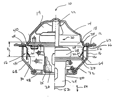
A thermos-tat is indicated generally as 10 in
Figure 1. The thermostat 10 -is a high flow type of i~
thermostat used in automobile cooling systems. While the
preferred embodiment relates to automotive thermostats, it
will be appreciated that the present invention is not
' 20897~
. - 5 -
limited to such thermostats, and may be used in many other
types of thermostats which operate in a similar manner.
The thermostat 10 consists of a generally
circular flange 12 surrounded by a valve supporting means
comprising an upper bridge 14 and a lower bridge 16. As
can be seen in Figure 2, the upper bridge 14 spans an
opening 18 which is generally circular. The upper bridge
14 is cut away on opposite sides to form a further opening
19 on either side of the upper bridge 14. In the preferred
embodiment of the Figures, the upper bridge is ~ormed in
one piece with the flange 12, whereas the lower bridge 16
is a separate piece fastened onto the ~lange 12.
Figure 1 also shows a temperature sensitive
valve indicated generally at 20 which comprises a pin 22
contacting the underside of the bridge 14 at one end and
housed within a body 24 at the other end. The body 24
contains a rubber boot 25 containing a temperature
;~ sensitive displacement means 26 as shown in the broken
away portion of Figure 1. The temperature sensitive
displacement means 26 responds to the temperature of a
surrounding fluid as further described below. It will be
- appreciated that the left sides of Figures l and 5 show
the valve 20 in a closed position, and the right sides
show the valve 20 in a fully open position. These
positions are described further below.
; Also attached to the body 24 is a valve disk 27
which is secured around an end cap 28 of the body 24. The
underside of the valve disk 27 is contacted by one end o~
a spring 32. The spring 32 is supported at the other end
by lower bridge 16. Preferably, in the installed position,
the spring 32 is under some compression whereby the valve
disk 27 is urged into engagement with a shoulder 34 which
surrounds the opening 18. The shoulder 34 provides a good
~- sealing surface and i~ desired, the valve disk 27 may
further include a rubber sealing gasket (not shown). Also
shown is a jiggle pin 40 which is located in an opening 42
,. :-, :, : ::
, , . ~ i ,: :
- i ~: . , . ~ .
2089~0'~l
-- 6
~; formed within the valve disk 27 and which is described in
greater detail below.
The lower bridge 16 is typically secured to the
flange 12 at either side by points 44. Tabs are extended
'- 5 through the flange 12 and are then sheared off to form a
solid attachment between lower bridge 16 and flange 12.
The lower bridge 16 extends downwardly on either side
below the flange 12 along arms 46 which connect to a
bottom member 48. Bottom member 48 in turn has an opening
lG 50 which is large enough to accommodate the body 24. In
this manner, the body 24 is free to move axially along the
axis of line 52 in the direction of double-headed arrow
54.
Locking elements according to two embodiments of
15 the present invention are generally shown respectively at
56 in Figures 1 and 3, and 57 in Figures 5 and 7. In both
embodiments, the locking elements 56, 57 have an
attachment means generally indicated at 58 and a locking
means generally indicated at 60.
In the first embodiment of Figures 1 and 3, the
locking element 56 has an end portion 63 and a body
portion 64. The end portion 63 includes a pair of
apertures 66a through which are inserted the attachment
tabs of the lower bridge 16. The end portion 63 is urged
firmly against the flange 12 to secure the locking element
56 when the lower bridge 16 is secured to the flange 12 by
points 44. The end portion 63 may also be secured by
welding, brazing or other suitable ways of attachment as
will be known to those skilled in the art. To securely
lock the valve 20, it is preferred to provide at least two
locking elements 56, one attached to each arm 46 of the
lower bridge 16.
In the second embodiment of Figures 5 and 7, the
locking element 57 has an end portion 65 and body portions
67. The end portion 65 and body portions 67 have a similar
function as the corresponding elements in the first
embodiment. The end portion 65 is semi-annular and rests
2~8~7~
. -- 7 --
against the bottom member 48 of the lower bridge 16. The
spring 32 urges the end portion 65 against the bottom
member 48 to hold the locking element 57 in place. There
are two preferred configurations of end portion 65,
namely, one with an opening to allow the locking element
57 to be assembled on to the thel~ostat after the
thermostat is fully made, or the bottom portion can be
formed as a closed circle which is assembled under the
spring as the thermostat is assembled. As seen in Figure
7, the locking element 57 has two body portions 67 which
are adapted to extend on opposing sides of the valve 20 to
securely lock the valve 20.
For both embodiments, the body portions 64, 67
of the locking elements 56, 57 are shaped to generally
follow the profile of the adjacent arm 46 of the :Lower
bridge 16. The body portions 64, 67 are located outside of
a path 68 that the periphery of the valve disk 27 follows
when the body 24 moves along the axis 52 in the direction
of double arrow 54.
20In both embodiments, the locking means 60
comprises a tab 61 that extends at an angle inwardly and
downwardly from the body portion 64, 67 into the path 68
of the valve disk 27. Alternatively, the locking means 60
could be an aperture defined in the body portion 64, 67
that is adapted to receive the periphery of the valve disk
27 to lock the valve 20 (in such a case, the body portion
64, 67 would extend into the path 68 of the valve disk 27
to enable the locking means 60 to operate). In a further
~ alternative, the locking elements 56, 57 could be attached
~30 to the underside of the valve disk 27, and the locking
means 60 could be spring biased against the arms 46 of the
lower bridge 16. In such a case, the spring biased locking
'~means 60 could extend through an aperture in the arm 46 to
lock the valve 20.
: 35In the embodiments depicted in the Figures, the
body portion 64, 67 is spaced from the arm 46 of the lower
~ bridge 16 at the point where the tab 61 is located. As
;' ' ~.
208~7~
'!
- 8 -
; shown in Figure 4, the space allows the body portion 64,
67 to flex outwardly towards the adjacent arm 48 to
accommodate the passage of the valve disk 27 as it moves
along the path 68. When the valve disk 27 moves downwardly
.~ 5 past the locking means 60, the body portion 64, 67 springs
back to its original position and the tab 61 blocks the
return path 68 of the valve disk to prevent the valve disk
27 from being urged by the spring 32 back to its closed
position.
As shown in Figures 3 and 7, the locking element
56, 57 is formed from a single piece of resiliently
flexible material, such as stainless steel or other
~ material. The tab 61 is cut from the body portion 64, 67
!~ and bent inwardly into the path of the valve disk 27.
' lS Alternatively, the locking elements 56, 57 could be formed
from a rigid material, such as steel, and combined with a
spring to provide the spring biased locking means 60
described earlier. For automobile thermostats, the locking
means 60 should be capable of resisting a force of up to
50 kilograms. The ilexing capacity of such thermostats
should be between 3 and 10 kilograms approximately.
For both embodiments, the tab 61 terminates in
an engaging surface 70 that is spaced a pre-determined
locking distance D~ from the shoulder 34. The engaging
surface 70 defines the point at which the valve disk 27
~' becomes locked. The engaging surface 70 engages the valve
disk 27 to prevent the valve disk 27 from returning to the
closed position. The pre-determined locking distance D~
corresponds to the distance the valve disk 27 is displaced
when the thermostat 10 has been subjected to a pre-
- determined extreme temperature T~ as described further
below.
The thermostat 10 is installed in the liquid
cooling system of a vehicle. For example, the thermostat
10 may be installed on the upper return line of the
cooling system in line with the cooling liquid so that the
cooling liquid has to flow through and around the
20897
~'
'~ g
..
thermostat 10 in order to circulate. The return line then
feeds into the top of a radiator structure or heat
exchanger which acts as a way of dissipating excess heat
carried by the cooling liquid. A line then is fed from the
bottom of the radiator to a water pump or the like which
typically forces the liquid back into the engine block
where the cooled liquid is used to cool portions of the
engine block (by absorbing heat). As will be appreciated
by those familiar with engines, in other systems, the
thermostat may be placed in the bottom and the circulation
will go in the opposite direction from the bottom to the
top.
The thermostat 10 is situated in the cooling
line in such manner that the body 24 is exposed to the
heated cooling fluid. It is preferable for the body 24 to
be fully immersed and therefore the valve 10 may be
'located somewhat below the highest liquid level of the
coolant in the cooling system, on the engine side.
When the motor or vehicle is running, heat is
generated in the engine block which in turn is passed into
the liquid coolant. As the temperature of the coolant
rises, the temperature rises around body 24. This has the
effect of causing temperature sensing means 26 to expand.
;~As temperature sensing means 26 expands, the pin 22 is
forced axially outwardly of the bod~ 24. The end of the
pin 22 engages the underside of the bridge 14 which in
turn causes the body 24 to move axially in the direction
of arrow 54. This unseats the groove 30 of the valve disk
27 from the shoulder 34 allowing cooling fluids to pass
through opening 18 and out openings l9. The fluids then
are permitted to return to the ra~iator or heat exchanger.
The purpose of the jiggle pin 40 is to provide
a form of pressure relief across the valve 20. In the
event that the liquid coolant heats up too quickly, for
~35 example, a pressure differential can be built up under the
;~valve disk 27. Such pressure is permitted to escape past
the jiggle pin 40 before it builds up to an extent which
: .:
-' 20897~
. .
- 1 0 -
~ would prevent the pin 22 from pushing the valve to an open
position. As wili be appreciated, if there was a great
pressure differential between the two sides of the valve
disk 27, this would require much more work by the pin 22
S to open the valve which is undesirable.
' Figure 8 provides a diagram showing the
displacement of the valve disk 27 relative to changes in
temperature.
As shown, the valve disk 27 is displaced under
normal working conditions from its initial position D; at
initial temperature Tj up to a distance Dw at a r~ x; mllr
normal working temperature Tw. The range be-tween
temperatures T; and ~w is the normal working zone of the
thermostat and will vary according to the design
characteristics of the thermostat.
As the temperature exceeds Tw, the valve disk 27
is further displaced, and then will reach the pre-
determined locking distance DL at the pre-determined
extreme temperature T~ The range between temperatures Tw
and TL is an overheating buffer zone for the thermostat.
While the temperatures in this zone exceed the normal
working temperatures of the thermostat, they are not
considered to be high enough that pe_ -nent damage is
likely to occur to either the motor, or the thermostat
itself.
At the pre-dete ined extreme temperature TL the
thermostat is being subjected to ex-treme overheating and
at this point there may be a risk of damage to the
thermostat and to the motorO Further increases in
temperature above the pre-determined temperature TL cause
a further displacement of the valve disk 27 up to a
failure distance Df where a failure temperature T~ is
reached. At this point, the internal compon~nts of the
thermostat 10 will absolutely fail. For conventional
automotive thermostats, failure typically occurs when the
internal rubber boot 25 containing the temperature
sensitive wax 26 becomes damaged at temperature Tf. When
'' ''208970ll
i
the thermostat has failed, the pin 22 no longer acts to
force the valve disk 27 axially outwardly from the body 24
and consequently the spring 32 urges the valve disk 27
~ upwardly towards the closed position against the shoulder
~ 5 34. However, since the valve disk 27 has been displaced
beyond the pre-determined distance D~ the locking means 60
preven~s the valve disk 27 from returning to the closed
position.
The pre-deterrined locking distance D~ is thus
set between the r~x;ll normal working distance Dw and ths
failure distance D~. Preferably, the overheating buffer
-~ zone is provided to account for minor, non-detrimental,
temperature increases above the working zone. However,
once DL has been reached, the engaging surface 70 will
engage the valve disk 27 to prevent the valve disk 27 from
returning to the closed position.
It will be appreciated by one skilled in the art
that the operating parameters of the thermostat lO will
vary according to the particular operatiny parameters of
the cooling system for which it is designed. By way of
example, a table of operating parameters for a sampling of
differently rated automotive cooling system thermostat is
provided below (with tolerances shown in brackets). It
should be noted that for such thermostats full opening of
the valve 20 is typically required at the maximum normal
working temperature Tw. The corresponding ~x; I normal
working displacement distance Dw is typically between 7 and
8 mm (as indicated below) r although the average working
displacement typically is less, approximately one half of
the ~xi , , about 3.5 to 4 mm.This forms an average
working zon0 as shown in Figure 8 as 9O. The limits of
this zone will vary depending upon particular engine
characteristics. At 92, another zone is shown which
represents a beginning ~o overhea~ condition.
.~
~,
: . .. ~ . , ,
~ ,., ~ ,.
.. : . , . ,
20897~
- 12 -
Ratings
71~C 77~C 82~C 88~C 91~C
(~2~C) (+2~C)(+2~c) (+2~C)(+2~C)
Dj (mm) 0 0 0 0 0
T; (~C) 71 77 82 88 91
Dw (mm)7 to 87 to 87 to 8 7 to 87 to 8
~ approx )
Tw (~C) 81 87 92 98 101
D~ (mm) 9.5 9.5 9.5 9.5 9.5
(approx)
TL (~C) 93 85 90 96 99
Df (mm~ 11 ll 11 11 11
10 ~ ~pprox )
Tf (~C) 135 135 135 135 135
It can now be appreciated how the present
invention operates. Under normal working conditions, the
- valve 20 will operate in a conventional manner to control
the flow of coolant through the opening 18. As the
operating temperatures increase beyond the normal working
temperatures, the valve will continue to operate. Nhen the
operating temperatures exceed the pre-determined locking
; temperature TL (at which point extreme overheating is
occurring), the locking means 60 blocks the return path 68
of the valve 20 to lock the thermostat 10 in an open
position. Thereafterl if the thermosta~ is subjected to
such extreme temperatures that failure occurs, the locking
means 60 prevents the valve 20 from returning to seal the
opening 18. Thus, unlike conventional thermostats, the
locking means 60 ensures that the valve remains open
before, during, and after the thermostat fails due to
ov~rheating.
208970~
.~ .
- 13 ~-
.
. It will be appreciated that the preferred
locking is achieved by two locking means, one on each side
of the valve 27. Even once locked, the locking means may
be released, by a simple use of a screwdriver point or the
like.
It will be appreciated that the foregoing
description is in respect of a preferred embodiment of the
invention and that various modificat:ions are possible
within the broad scope of the appended claims. Some of
these modifications have been discussed above and others
will be apparent to those skilled in the art. For
/- instance, the locking element 56, 57 may be used with many
'' types of automotive thermostats, including by-pass
thermostats, or may be used for any heating systems in
which temperature control is applied. The locking element
' 56, 57 may be adapted for use in other types and
configurations of thermostats or heat controllers not
necessarily d~rected to auto;otive cooling systems.
:'
.
.. ,,, ~ . .. . .. .. . .