Language selection

Search

Patent 2159968 Summary

Third-party information liability

Some of the information on this Web page has been provided by external sources. The Government of Canada is not responsible for the accuracy, reliability or currency of the information supplied by external sources. Users wishing to rely upon this information should consult directly with the source of the information. Content provided by external sources is not subject to official languages, privacy and accessibility requirements.

Claims and Abstract availability

Any discrepancies in the text and image of the Claims and Abstract are due to differing posting times. Text of the Claims and Abstract are posted:

  • At the time the application is open to public inspection;
  • At the time of issue of the patent (grant).
(12) Patent: (11) CA 2159968
(54) English Title: PROTECTIVE MEMBER FOR A VEHICLE
(54) French Title: ELEMENT DE PROTECTION POUR VEHICULE
Status: Expired
Bibliographic Data
(51) International Patent Classification (IPC):
  • B60R 19/54 (2006.01)
  • B62D 25/00 (2006.01)
(72) Inventors :
  • BARTLEY, ROBERT WILLIAM (New Zealand)
(73) Owners :
  • ROBERT WILLIAM BARTLEY, ANN MARIE BARTLEY AND REX IAN MCKINNON, TOGETHER AS TRUSTEES OF THE R W B TRUST (New Zealand)
(71) Applicants :
  • BARTLEY, ROBERT WILLIAM (New Zealand)
(74) Agent: GOWLING LAFLEUR HENDERSON LLP
(74) Associate agent:
(45) Issued: 2011-11-01
(22) Filed Date: 1995-10-05
(41) Open to Public Inspection: 1997-04-06
Examination requested: 2002-08-27
Availability of licence: N/A
(25) Language of filing: English

Patent Cooperation Treaty (PCT): No

(30) Application Priority Data: None

Abstracts

English Abstract


A device for a vehicle (2) comprising a protective member (1) spanning a
section of the
vehicle (1), and mounting means to mount the protective member (1) to the
vehicle (2).
The protective device may be contructed of a plurality of interconnected
elements to
form a frame (15, 25, 38).


French Abstract

Un dispositif pour véhicule (2) comprend un élément protecteur (1) s'étendant sur une partie du véhicule (1), et un dispositif de montage pour installer l'élément protecteur (1) sur le véhicule (2). Le dispositif protecteur peut être constitué de multiples éléments interreliés pour former un châssis (15, 25, 38).

Claims

Note: Claims are shown in the official language in which they were submitted.


-8-


1. A protective member for a vehicle, said vehicle having a front end shape
defined in part
by an original vehicle bumper, said protective member including a replacement
bumper member
shaped substantially the same as the original vehicle bumper but formed from
substantially
heavier gauge material to provide enhanced resistance to deformation.


2. The protective member of claim 1 further including a plurality of
interconnected elements
secured to the replacement bumper to form a protective frame above the
replacement bumper
when the replacement bumper is secured to the vehicle.


3. The protective member of claim 1 or 2 wherein the replacement bumper
includes
apertures registering with indicator lights on the vehicle to allow the
indicator lights to beam
therethrough.


4. The protective member of claim 1, 2 or 3 wherein at least the replacement
bumper is
formed of a metal alloy.


5. The protective member of claim 4 wherein the metal alloy contains at least
one of steel
and aluminium.


6. The protective member of claim 5 wherein the alloy has a thickness of at
least 8mm.


Description

Note: Descriptions are shown in the official language in which they were submitted.


2159968
S
PROTECTIVE MEMBER FOR A VEHICLE
FIELD OF THE INVENTION

The present invention relates to a device for protecting vehicles. More
particularly, but
not exclusively, this invention relates to a device for protecting a vehicle
from being
damaged by minor external impacts.

BACKGROUND OF THE INVENTION

The damage caused to vehicles from minor impacts without the addition of extra
protection can be expensive. Damage to a vehicle may by prevented or minimised
by the
use of a protective device mounted to span a section of the vehicle to be
protected.

It is an object of the invention to provide a protective device for a vehicle
which
overcomes at least some of the abovementioned problems, or at least to provide
the
public with the useful choice.

SUMMARY OF THE INVENTION

According to an aspect of the invention there is provided a device for
protecting a vehicle
comprising a protective member spanning a section of the vehicle, and mounting
means
to mount the protective member to the vehicle.

It will be appreciated the invention has particular advantage when installed
on vehicles
used in environments where minor impacts to a vehicle are more frequent than
in normal
driving environments. These environments include off-road places such as farms
and forests.

2159968
I
-2-
Preferably the protective member comprises a plurality of interconnected
elements to
form a frame. Preferably the frame is mounted between the rear of the cab of
the vehicle
such that the frame protects the cab from a load being hauled.

Alternatively the frame is preferably mounted at the front or the rear of the
vehicle and
is ancillary to the bumper of the vehicle.

Preferably the protective member is adapted to replace an existing bumper of a
vehicle
or is ancilliary to the bumper of the vehicle.

Preferably the protective member is formed of a durable material such as steel
or an
alloy. Preferably the protective member is formed of 12mm alloy.

BRIEF DESCRIPTION OF THE DRAWINGS

This invention is now described by way of example with reference to the
accompanying
drawings. The disclosures and the description are purely illustrative and are
not intended
to limit the application of the invention.

Figure 1 - shows a protective member in the form of a replacement and
strengthened vehicle bumper;

Figure 2 - shows a protective member in the form of the bumper of figure 1
with
uprights from the bumper to form a frame at the front end of a
vehicle;

2159968
i
-3-
Figure 3 - shows a protective member in the form of a frame or "bullbar"
mounted at the front of a vehicle according to an alternative
embodiment of the invention;

Figure 4 - shows a protective frame in the form of a rear guard at the rear of
a
truck cab according to an alternative embodiment of the invention.
DETAILED DESCRIPTION OF PREFERRED EMBODIMENTS OFTHE INVENTION
For the purposes of promoting an understanding of the invention, reference
will now be
made to various embodiments of the invention as illustrated in the drawings
and specific
language will be used to describe these embodiments. It will be understood
that no

limitation of the scope of the invention is intended, and alterations and
further
modifications may be made to the invention without departing from the scope of
the
invention as described.

Referring now to the drawings, figure 1 shows a protective member in the form
of an
upgraded and strengthened vehicle bumper 1. Bumper 1 is moulded to the shape
of the
lower front end of a truck 2 and matches the body lines of the truck 2. In
this example

the bumper 1 is designed to replace the original bumper on the truck 2. The
bumper 1
is made of a strong and durable material such as an alloy or steel. Preferably
the bumper
1 is constructed of 12mm alloy because of its lightness, strength, and its
mouldability.

Apertures 3 may be made in the bumper 1 to allow indicator lights of a vehicle
to beam
through the aperture in the bumper 1 when in use. Metal bumper attachments
(not

2159968
=
-4-
shown) are welded at one end to suitable places against the inside of the
bumper 1 and
are attached to the chassis of the truck 2 by bolts or by welded joints at the
other end
of the attachments.

Cutout sections 4 may be made in the bumper to allow access to any tow hooks
originally on the vehicle 2 to protrude through the cutout sections 4 in the
bumper 1
when the bumper 1 is attached to the vehicle 2.

A concave portion 5 may be formed in the bumper 1 and a steel bar 6 secured in
the
concave portion 5 by the bumper 1 to allow a hook to be retained about the
steel bar 6
for towing purposes.

The bumper 1 may be moulded of a width such that the bumper 1 forms a wide
skirt
(not shown) across the front of the vehicle or be modified with a rake (not
shown).

It is an advantage to have a replacement bumper formed of a strong alloy for
added
strength and durability. This design of bumper is particularly suitable for
use on a vehicle
used for agricultural, forestry, and/or quarry work.

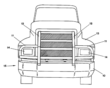
Referring now to figure 2, an alternative embodiment of the invention is
shown. A
bumper 10, similar in design to bumper 1, is moulded to either replace the
original
bumper of the truck 13 or be an addition to the original bumper as a bullbar.
The
bumper 10 is to be attached to the chassis of a truck 13 by suitable
attachment means
such as with bolts or by welding.

A plurality of interconnected elements form a frame 15 at the front of the
vehicle. These

2159968
i
-5-
interconnected elements include vertically extending uprights 12 made of metal
or alloy
which are attached to the bumper 10 and extend upwardly to a height to protect
the
front end of the truck 13. For added strength, sections of preferably alloy
tubing 11 are
attached to uprights 12 to form a solid frame 15 to protect the front of the
vehicle 13
from minor impacts.

The frame is designed to protect the particular front end of the vehicle, and
in this case
the frame is shaped to allow the beams of the headlights 14 to penetrate
between the
frame members.

Referring now to figure 3, an alternative embodiment of the invention in the
form of a
frame 25 or "bullbar" is shown. In this embodiment the original bumper remains
intact
on the vehicle. The frame 15 is attached to the chassis of the vehicle from
beneath the
bumper and protrudes at a spaced distance from the front of the vehicle.

Uprights 20, cross members 21, and a metal plate 22 are connected together to
form a
protective frame 25. A bottom rake 23 projecting beyond the plate 22 is
connected to
the bottom of the frame to provide further support for the frame 25. The bull
bar is
attached using bolts, or by welds, to the chassis of the vehicle by arms
attached to the
central uprights and extending underneath the bumper (not shown).

Preferably the plate 22 is made of 12mm alloy and the uprights 20 of 8mm
alloy.
Preferably the cross members 23 are made of 12mm alloy tubing.

Apertures 24 may be cut out of the plate 22 in appropriate places to allow the
beams
from indicator lights to pierce through.

2159968
=
-6-
Referring to figure 4, a protective frame 38 showing a rear guard to protect
the cab of
a truck, is illustrated.

Two vertically extending uprights 30 are connected to a bracket 31 which is
itself
connected to the top section of the chassis of a truck. Tubing 32 is shaped to
define the
frame 38 which follows the width and height of the rear of the cab of a truck.
The
tubing 32 is welded to the other ends of the uprights 30 from the bracket 31.

Cross members 33, 34, 35 are welded perpendicular to the uprights 30 within
the tubing
32 to give the frame 38 added strength. Mesh 36 is preferably attached to the
cab side
of the frame 38 above the cross member 34 to allow a driver to view the road
from the

rearview mirror of the cab when the truck is not hauling. A metal plate 37 is
attached
to the cab side of the frame 38 between the outer frame 32 and below the cross
member
34 to the bottom tubing 32 for added protection and strength.

The protective frame 38 in this instance protects the cab from any load being
hauled
from behind the cab in the event of the load being pushed into the cab.

Where in the aforegoing description reference has been made to specific
components or
integers of the invention having known equivalents, then such equivalents are
herein
incorporated as if individually set forth.

Although this invention has been described by way of example and with
reference to
possible embodiments thereof, it is to be understood that modifications and
improvements may be made thereto without departing from the scope of the
invention


S 2159968
as appended in the claims.

Representative Drawing
A single figure which represents the drawing illustrating the invention.
Administrative Status

For a clearer understanding of the status of the application/patent presented on this page, the site Disclaimer , as well as the definitions for Patent , Administrative Status , Maintenance Fee  and Payment History  should be consulted.

Administrative Status

Title Date
Forecasted Issue Date 2011-11-01
(22) Filed 1995-10-05
(41) Open to Public Inspection 1997-04-06
Examination Requested 2002-08-27
(45) Issued 2011-11-01
Expired 2015-10-05

Abandonment History

Abandonment Date Reason Reinstatement Date
2006-09-22 R30(2) - Failure to Respond 2007-01-10
2006-10-05 FAILURE TO PAY APPLICATION MAINTENANCE FEE 2007-01-10
2010-01-25 R30(2) - Failure to Respond 2010-12-23

Payment History

Fee Type Anniversary Year Due Date Amount Paid Paid Date
Application Fee $0.00 1995-10-05
Registration of a document - section 124 $0.00 1996-05-23
Maintenance Fee - Application - New Act 2 1997-10-06 $50.00 1997-10-02
Maintenance Fee - Application - New Act 3 1998-10-05 $50.00 1998-09-15
Maintenance Fee - Application - New Act 4 1999-10-05 $50.00 1999-09-02
Maintenance Fee - Application - New Act 5 2000-10-05 $75.00 2000-07-25
Maintenance Fee - Application - New Act 6 2001-10-05 $75.00 2001-10-04
Request for Examination $200.00 2002-08-27
Maintenance Fee - Application - New Act 7 2002-10-07 $75.00 2002-10-07
Advance an application for a patent out of its routine order $100.00 2002-12-04
Maintenance Fee - Application - New Act 8 2003-10-06 $75.00 2003-09-29
Registration of a document - section 124 $100.00 2004-08-24
Maintenance Fee - Application - New Act 9 2004-10-05 $100.00 2004-10-05
Maintenance Fee - Application - New Act 10 2005-10-05 $125.00 2005-10-05
Reinstatement - failure to respond to examiners report $200.00 2007-01-10
Reinstatement: Failure to Pay Application Maintenance Fees $200.00 2007-01-10
Maintenance Fee - Application - New Act 11 2006-10-05 $250.00 2007-01-10
Expired 2019 - Corrective payment/Section 78.6 $1,025.00 2007-01-29
Maintenance Fee - Application - New Act 12 2007-10-05 $250.00 2007-10-05
Maintenance Fee - Application - New Act 13 2008-10-06 $250.00 2008-10-06
Maintenance Fee - Application - New Act 14 2009-10-05 $250.00 2009-09-17
Maintenance Fee - Application - New Act 15 2010-10-05 $450.00 2010-10-01
Reinstatement - failure to respond to examiners report $200.00 2010-12-23
Final Fee $300.00 2011-08-29
Maintenance Fee - Application - New Act 16 2011-10-05 $450.00 2011-08-29
Maintenance Fee - Patent - New Act 17 2012-10-05 $450.00 2012-09-28
Maintenance Fee - Patent - New Act 18 2013-10-07 $450.00 2013-10-03
Maintenance Fee - Patent - New Act 19 2014-10-06 $450.00 2014-07-17
Owners on Record

Note: Records showing the ownership history in alphabetical order.

Current Owners on Record
ROBERT WILLIAM BARTLEY, ANN MARIE BARTLEY AND REX IAN MCKINNON, TOGETHER AS TRUSTEES OF THE R W B TRUST
Past Owners on Record
BARTLEY, ROBERT WILLIAM
RW & AM BARTLEY LIMITED TRADING AS ALI ARC INDUSTRIES
Past Owners that do not appear in the "Owners on Record" listing will appear in other documentation within the application.
Documents

To view selected files, please enter reCAPTCHA code :


To view images, click a link in the Document Description column. To download the documents, select one or more checkboxes in the first column and then click the "Download Selected in PDF format (Zip Archive)" or the "Download Selected as Single PDF" button.

List of published and non-published patent-specific documents on the CPD .

If you have any difficulty accessing content, you can call the Client Service Centre at 1-866-997-1936 or send them an e-mail at CIPO Client Service Centre.


Document
Description 
Date
(yyyy-mm-dd) 
Number of pages   Size of Image (KB) 
Abstract 2011-09-27 1 6
Claims 2006-02-01 1 26
Representative Drawing 1997-09-30 1 14
Representative Drawing 2000-12-08 1 14
Claims 2003-07-02 1 29
Abstract 1995-10-05 1 6
Cover Page 1995-10-05 1 10
Description 1995-10-05 7 152
Claims 1995-10-05 1 17
Drawings 1995-10-05 4 56
Cover Page 2000-12-08 1 10
Claims 2005-02-18 1 22
Claims 2004-04-14 1 20
Claims 2004-11-24 1 22
Representative Drawing 2011-09-09 1 13
Cover Page 2011-09-29 1 38
Abstract 2011-10-31 1 6
Drawings 2011-10-31 4 56
Description 2011-10-31 7 152
Cover Page 2012-04-24 2 79
Correspondence 2007-04-03 1 16
Assignment 2005-06-07 2 73
Fees 1998-09-15 1 53
Prosecution-Amendment 2006-02-01 5 257
Assignment 2004-08-24 3 81
Fees 2002-10-07 1 35
Fees 2005-10-05 1 17
Correspondence 2004-10-06 1 17
Prosecution-Amendment 2010-03-03 1 45
Prosecution-Amendment 2008-01-29 13 671
Assignment 1995-10-05 9 387
Prosecution-Amendment 2002-08-27 1 39
Correspondence 1996-07-10 1 25
Prosecution-Amendment 2002-12-04 2 64
Prosecution-Amendment 2002-12-19 1 12
Prosecution-Amendment 2003-03-03 2 60
Prosecution-Amendment 2003-04-03 114 9,009
Prosecution-Amendment 2003-04-14 2 26
Prosecution-Amendment 2003-07-02 3 116
Prosecution-Amendment 2003-10-17 3 85
Prosecution-Amendment 2003-11-14 2 69
Correspondence 2003-12-05 1 12
Fees 2004-10-05 1 33
Prosecution-Amendment 2007-01-10 4 246
Prosecution-Amendment 2005-02-18 4 164
Fees 1997-10-02 1 52
Prosecution-Amendment 2004-04-14 4 162
Prosecution-Amendment 2004-05-31 2 72
Prosecution-Amendment 2004-07-06 69 2,937
Prosecution-Amendment 2004-07-20 2 24
Prosecution-Amendment 2004-11-24 4 156
Prosecution-Amendment 2004-12-22 4 163
Correspondence 2005-03-14 1 17
Prosecution-Amendment 2005-06-01 1 34
Prosecution-Amendment 2005-08-01 5 214
Prosecution-Amendment 2006-03-22 3 102
Prosecution-Amendment 2011-07-28 23 1,468
Fees 2007-01-10 1 30
Prosecution-Amendment 2007-01-29 2 91
Prosecution-Amendment 2007-07-30 3 153
Prosecution-Amendment 2008-04-07 1 62
Correspondence 2010-02-04 5 182
Prosecution-Amendment 2009-01-23 3 83
Prosecution-Amendment 2009-07-23 4 161
Correspondence 2009-06-18 19 841
Prosecution-Amendment 2009-09-15 23 906
Fees 2009-09-17 1 44
Prosecution-Amendment 2009-12-04 2 52
Correspondence 2010-01-11 2 65
Correspondence 2010-01-21 1 19
Correspondence 2011-08-24 1 14
Prosecution-Amendment 2010-01-22 3 114
Correspondence 2011-08-29 5 180
Fees 2011-08-29 1 202
Correspondence 2010-04-30 2 77
Correspondence 2010-06-03 6 246
Correspondence 2010-06-29 2 64
Correspondence 2010-07-07 1 16
Correspondence 2010-07-07 1 19
Prosecution-Amendment 2010-12-23 3 94
Prosecution-Amendment 2011-01-28 5 258
Correspondence 2010-06-10 9 351
Correspondence 2011-11-04 1 45
Correspondence 2011-11-14 3 75
Prosecution-Amendment 2012-04-24 2 59