Language selection

Search

Patent 2175673 Summary

Third-party information liability

Some of the information on this Web page has been provided by external sources. The Government of Canada is not responsible for the accuracy, reliability or currency of the information supplied by external sources. Users wishing to rely upon this information should consult directly with the source of the information. Content provided by external sources is not subject to official languages, privacy and accessibility requirements.

Claims and Abstract availability

Any discrepancies in the text and image of the Claims and Abstract are due to differing posting times. Text of the Claims and Abstract are posted:

  • At the time the application is open to public inspection;
  • At the time of issue of the patent (grant).
(12) Patent: (11) CA 2175673
(54) English Title: IMPROVEMENTS IN GROUND ANCHORS
(54) French Title: AMELIORATIONS APPORTEES A DES TIRANTS D'ANCRAGE
Status: Expired
Bibliographic Data
(51) International Patent Classification (IPC):
  • E02D 5/80 (2006.01)
  • E02D 5/74 (2006.01)
  • F16G 11/00 (2006.01)
  • F16G 11/10 (2006.01)
(72) Inventors :
  • AGG, CHARLES SIMON JAMES (United Kingdom)
(73) Owners :
  • PLATIPUS ANCHORS LIMITED (United Kingdom)
(71) Applicants :
  • PLATIPUS ANCHORS LIMITED (United Kingdom)
(74) Agent: RICHES, MCKENZIE & HERBERT LLP
(74) Associate agent:
(45) Issued: 2004-12-07
(86) PCT Filing Date: 1994-05-18
(87) Open to Public Inspection: 1995-05-11
Examination requested: 2000-04-03
Availability of licence: N/A
(25) Language of filing: English

Patent Cooperation Treaty (PCT): Yes
(86) PCT Filing Number: PCT/GB1994/001066
(87) International Publication Number: WO1995/012713
(85) National Entry: 1996-05-02

(30) Application Priority Data:
Application No. Country/Territory Date
9322642.1 United Kingdom 1993-11-03

Abstracts

English Abstract


The invention relates to ground anchors (10) of the type which are attached to cables and rods and driven into the ground and tilted
transversely by tensioning the cable. A ground anchor comprising a body portion (11) having a generally triangular cross section extending
substantially along its length having generally concave sides and a continuous convex lower surface from one edge of the body portion
where the sides and lower suface meet to an opposite edge.


French Abstract

L'invention se rapporte à des tirants d'ancrage (10) du type de ceux qui sont fixés à des câbles et à des barres, enfoncés dans le sol puis basculés transversalement par tension du câble. Un tirant d'ancrage comprend un corps (11) généralement de coupe triangulaire, s'étendant sensiblement sur sa longueur, doté de côtés généralement concaves ainsi que d'une surface inférieure continue convexe s'étendant à partir d'un bord de la portion du corps où se rencontrent les côtés et la surface inférieure, jusqu'au bord opposé.

Claims

Note: Claims are shown in the official language in which they were submitted.


-6-


The embodiments of the invention in which an exclusive
property or privilege is claimed are defined as follows:

1. A ground anchor comprising a body portion having a
generally triangular cross-section extending substantially
along a length thereof having generally concave sides and a
continuous convex lower surface from one edge of the body
portion where the sides and lower surface meet to an
opposite edge.

2. An anchor as claimed in claim 1 in which the edges of
said body portion curve upwardly where the sides and lower
surface meet.

3. An anchor as claimed in claim 1 in which the edges of
said body portions angle upwardly where the sides and lower
surface meet.

4. An anchor as claimed in any one of claims 1 to 3 in
which edges of said body portion where the sides and lower
surface meet are rounded.

5. An anchor as claimed in any one of claims 1 to 4
further comprising a driving edge formed at one end of said
body portion.

6. An anchor as claimed in any one of claims 1 to 5 in
which the body portion extends upwardly to form a keel
member in which is formed an anchor eye.

7. An anchor as claimed in any one of claims 1 to 5 in
which a keel member is formed on the body portion in which
is formed a socket.


-7-

8. An anchor as claimed in claim 6 or claim 7 in which the
keel member is convergent in a horizontal or vertical plane
from the eye portion or socket to the driving edge.

9. A ground anchor comprising a body portion having a
generally triangular cross-section extending substantially
along a length thereof and having generally concave sides
and a lower surface, said lower surface and said concave
sides meeting to form a first edge and a second edge,
wherein said lower surface is continuously convex between
said first and second edges.

10. An anchor as claimed in claim 9 in which said first
edge and said second edge curve upwardly from a horizontal
plane.

11. An anchor as claimed in claim 10 wherein said first and
second edges are rounded.

12. An anchor as claimed in claim 11 further comprising a
driving edge formed at an end of said body portion.

13. An anchor as claimed in claim 12 wherein said body
portion extends upwardly to form a keel member having an
anchor eye.

14. An anchor as claimed in claim 13 wherein said keel
member tapers downwardly to said driving edge.

15. An anchor as claimed in claim 14 wherein said keel
member is convergent to the horizontal plane.


-8-


16. An anchor as claimed in claim 12 wherein said body
portion includes a keel member having a socket.

17. An anchor as claimed in claim 16 wherein said keel
member tapers downwardly to said driving edge.

18. An anchor as claimed in claim 17 wherein said keel
member is convergent to the horizontal plane.

19. An anchor as claimed in claim 6 or claim 7 in which the
keel member is convergent in a horizontal and vertical plane
from the eye portion or socket to the driving edge.


Description

Note: Descriptions are shown in the official language in which they were submitted.


- WO 95112713
217 5 6 7 3 p~lGg94/01066
- 1 -
IMPROVEMENTS IN GROUND ANCHORS
The invention relates to ground anchors of the
type which are attached to cables and rods and driven
into the ground and tilted transversely by tensioning
the cable.
A variety of ground anchors already exist
including tubular anchors, such as those described in
GB-A-1555580 and EP-A-0208153. These anchors are
driven into the ground and then rotated to a
horizontal locked position. As the surface area of
these anchors is not particularly large, they are not
appropriate for some uses where a particular degree
of strength and resistance to removal from the ground
is required.
Improvements have been made to such anchors
which resulted in the addition of wings to provide a
greater planar or surface area to resist the anchors
from being pulled from the ground once in their
tilted locked position. Examples of such wing
anchors are known from EP-A-0313936, US-A-4574539 and
US-A-3282002. Each of these anchors has different
specific features which enable the anchors either to
be easily driven into the ground, to prevent its
withdrawal therefrom or to ease the ability of rotate
the anchor once embedded in the ground.
However, in hard ground conditions wing-type
anchors are not generally suitable because of the
increase in the quantity of ground media to be
moved. For such conditions high capacity small
profile anchors, such as the original tubular
anchors, are most suitable.
It is therefore an object of the present
invention to further improve anchors of the small
profile type in these respects.
according to the invention there is provided a


CA 02175673 2000-OS-09
- 2 -
ground anchor comprising a body portion having a
generally triangular cross-section extending
substantially along its length having generally concave
sides and a continuous convex lower surface from one edge
of the body portion where the sides and lower surface
meet to an opposite edge.
In an aspect of the present invention, there is
provided a ground anchor comprising a body portion having
a generally triangular cross-section extending
substantially ,slong a length thereof and having generally
concave sides ,end a lower surface, said lower surface and
said concave sides meeting to form a first edge and a
second edge, wherein said lower surface is continuously
convex between said first and second edges.
Preferabl:~r the edges of said body portion curve or
angle upwardly where the sides and lower surface meet.
Edges of said body portion where the sides and lower
surface meet a:re preferably rounded.
In a preferred embodiment of the invention the
anchor comprises a driving edge formed at one end of said
body portion.
Preferable the :body portion extends upwardly to form
a keel in which is formed an anchor eye. Alternatively a
keel portion is formed on the body portion in which is
formed a socket=.
The keel rnember is preferably convergent in a
horizontal and;or vertical plane from the eye portion or
socket to the driving edge.
A preferred embodiment of the invention will now be
described, by way of example only, with reference to the
accompanying drawings, in which:-


CA 02175673 2000-OS-09
- 2a -
Fig. 1 is a plan view of an anchor according to the
invention;
Fig. 2 is a side elevation of the anchor of Fig. l;
Fig. 3 is a front elevation of the anchor of Fig. 1;
Fig. 4 is a rear elevation of the anchor of Fig. 1;


_ WO 95/12713 21 l 5 b 7 3
PCT1GB94I01066
- 3 -
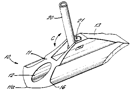
Fig. 5 is a schematic view of the anchor of
Fig. 1 with the eye replaced with a swaged fitting;
Fig. 6 is a partial schematic view of the
swaged fitting of Fig. 5 with parts omitted for
clarity; and
Figs. 7a-7c are schematic views of the
installion steps applied to a prior art anchor.
As shown in Figs. 1-4 the anchor 10 comprises a
generally triangular or bell-shaped body 11 having an
axially extending blind bore 12 for receiving a
driving tool. When viewed from one end, the anchor
10 is seen to have a triangular bell-shaped profile
for a substantial length along its working surface.
The sides of the anchor body 11 are, in profile,
continuously concave from an upper edge of the
working surface to edges 16 where the sides and lower
surface meet. The lower surface of the body I1 is
continuously convex from edge to edge. The edges 16,
may curve or angle slightly upwardly from the
horizontal. These edges 16 may be rounded or edge
beads provided. It is to be noted that the use of
the terms "concave" or "convex" are intended to
include not only inwardly or outwardly rounded
surfaces, but also surfaces which have flat regions
which may be angled to other flat regions but which
overall give an impression of concavity or convexity.
The body I1 extends upwardly to form a high
keel 13 in which is formed an anchor eye 14 to which
a cable may be attached. The high keel 13, which
starts from the anchor eye 14, tapers downwardly
towards a driving edge 15. The driving edge 15 may
be sharpened to a chisel point. The keel 13 may also
converge in the horizontal direction to form a point


WO95112713 2175673
PCT/GB94I01066
- 4 -
as it approaches the driving edge 15. The body
portion 11 has a sharp tapering nose 11a at an end
opposite to the driving edge 15.
In an alternative embodiment of the invention,
as shown in Figs. 5 and 6, the eye 14 is replaced
with a T-shaped swaged fitting 20. The fitting 20 is
inserted into a socket 21 formed in the keel 13 with
the cross bar 22 positioned longitudinally to the
body lI. The fitting 20 can then be rotated through
90° to the position shown in Figs. 5 and 6 whereby
the T-piece 22 is anchored in the socket 21 under the
keel 13. The fitting 20 can then pivot in the
direction of the arrow C.
In this embodiment of the invention, the
working surface of the anchor extends to below the
keel 13.
In use, a cable or rod is attached to the eye
portion 14 or swaged fitting 20 and a driving rod is
inserted into the bore 12. The anchor 10 is driven
into the ground, driving edge 15 first to its
installed position, by applying a force to the
driving rod. Fig. 7a illustrates the installed
position of a prior art anchor.
The driving edge 15 splits the ground media by
way of separating the upper side and lower side and
compresses the media out of the way. This enhances
the ability of the anchor 10 to drive more quickly
and easily through harder media. The high keel 13
further enhances significantly the ability of the
anchor 10 to drive straight through difficult
anchoring media.
Once the anchor 10 has reached its desired
depth, the drive rod is removed from the bore 12. A
pulling force is applied to the cable or rod which
causes the anchor 10 to rotate in the ground to a
generally horizontal load locked position (see Fig.

_ WO 95/12713 217 5 6 7 3
- 5 -
PCT/GB94/01066
7A-B). Once the sharp nose lla of the body 11 bites
the back of the hole into which the anchor 10 is
driven, this forms a fulcrum for the anchor 10 to
turn about. The upwardly curved edges 16 of the
anchor body 11 help to consolidate the turn of the
anchor 10.
The triangular or bell-shaped working surface
area of the anchor 10 offers a significant increase
in potential load over traditional tube-style anchors
whilst the anchor remains a small profile anchor
which is necessary for hard ground conditions. The
shaped surface offers high load possibilities for a
small surface area anchor by focusing the frustrum of
soil more clearly.
The rounded edges 16 of the anchor 10 further
enhance the frustum area and reduce spill-off during
high loadings and therefore reduce mechanical shear.
The anchor 10 may be made from any suitable
material depending on its required use, such as
iron/steel, copper and brass based alloys, aluminium,
non-ferous materials and possibly non-metallic
materials.
30

Representative Drawing
A single figure which represents the drawing illustrating the invention.
Administrative Status

For a clearer understanding of the status of the application/patent presented on this page, the site Disclaimer , as well as the definitions for Patent , Administrative Status , Maintenance Fee  and Payment History  should be consulted.

Administrative Status

Title Date
Forecasted Issue Date 2004-12-07
(86) PCT Filing Date 1994-05-18
(87) PCT Publication Date 1995-05-11
(85) National Entry 1996-05-02
Examination Requested 2000-04-03
(45) Issued 2004-12-07
Expired 2014-05-20

Abandonment History

Abandonment Date Reason Reinstatement Date
1999-05-18 FAILURE TO PAY APPLICATION MAINTENANCE FEE 1999-10-28

Payment History

Fee Type Anniversary Year Due Date Amount Paid Paid Date
Application Fee $0.00 1996-05-02
Maintenance Fee - Application - New Act 2 1996-05-20 $100.00 1996-05-02
Registration of a document - section 124 $0.00 1996-08-01
Maintenance Fee - Application - New Act 3 1997-05-20 $100.00 1997-05-13
Maintenance Fee - Application - New Act 4 1998-05-19 $100.00 1998-05-15
Reinstatement: Failure to Pay Application Maintenance Fees $200.00 1999-10-28
Maintenance Fee - Application - New Act 5 1999-05-18 $150.00 1999-10-28
Request for Examination $400.00 2000-04-03
Maintenance Fee - Application - New Act 6 2000-05-18 $150.00 2000-05-17
Maintenance Fee - Application - New Act 7 2001-05-18 $150.00 2001-04-30
Maintenance Fee - Application - New Act 8 2002-05-21 $150.00 2002-05-13
Maintenance Fee - Application - New Act 9 2003-05-20 $150.00 2003-05-15
Maintenance Fee - Application - New Act 10 2004-05-18 $250.00 2004-05-13
Final Fee $300.00 2004-09-22
Maintenance Fee - Patent - New Act 11 2005-05-18 $250.00 2005-05-11
Maintenance Fee - Patent - New Act 12 2006-05-18 $250.00 2006-05-02
Maintenance Fee - Patent - New Act 13 2007-05-18 $250.00 2007-04-19
Maintenance Fee - Patent - New Act 14 2008-05-19 $250.00 2008-04-30
Maintenance Fee - Patent - New Act 15 2009-05-18 $450.00 2009-04-21
Maintenance Fee - Patent - New Act 16 2010-05-18 $450.00 2010-05-10
Maintenance Fee - Patent - New Act 17 2011-05-18 $450.00 2011-05-16
Maintenance Fee - Patent - New Act 18 2012-05-18 $450.00 2012-05-07
Maintenance Fee - Patent - New Act 19 2013-05-21 $450.00 2013-05-06
Owners on Record

Note: Records showing the ownership history in alphabetical order.

Current Owners on Record
PLATIPUS ANCHORS LIMITED
Past Owners on Record
AGG, CHARLES SIMON JAMES
Past Owners that do not appear in the "Owners on Record" listing will appear in other documentation within the application.
Documents

To view selected files, please enter reCAPTCHA code :


To view images, click a link in the Document Description column. To download the documents, select one or more checkboxes in the first column and then click the "Download Selected in PDF format (Zip Archive)" or the "Download Selected as Single PDF" button.

List of published and non-published patent-specific documents on the CPD .

If you have any difficulty accessing content, you can call the Client Service Centre at 1-866-997-1936 or send them an e-mail at CIPO Client Service Centre.


Document
Description 
Date
(yyyy-mm-dd) 
Number of pages   Size of Image (KB) 
Representative Drawing 1997-06-17 1 4
Cover Page 1996-08-08 1 15
Claims 2003-06-06 3 76
Drawings 2003-06-06 3 49
Abstract 1995-05-11 1 40
Description 1995-05-11 5 182
Claims 1995-05-11 2 35
Drawings 1995-05-11 3 48
Claims 2000-06-27 3 74
Description 2000-05-09 6 195
Claims 2000-05-09 3 67
Cover Page 2004-11-02 1 40
Representative Drawing 2004-07-15 1 11
Fees 2000-05-17 1 37
Fees 1999-10-28 1 44
Fees 2008-04-30 1 53
Correspondence 2004-09-22 1 33
Assignment 1996-05-02 6 253
PCT 1996-05-02 8 250
Prosecution-Amendment 2000-04-03 1 38
Prosecution-Amendment 2000-05-09 8 168
Prosecution-Amendment 2000-06-27 5 125
Prosecution-Amendment 2002-12-06 2 49
Fees 2003-05-15 1 32
Prosecution-Amendment 2003-06-06 9 289
Prosecution-Amendment 2003-10-07 1 28
Prosecution-Amendment 2003-11-25 2 87
Fees 2002-05-13 1 37
Fees 2001-04-30 1 35
Fees 1998-05-15 1 36
Fees 2004-05-13 1 35
Fees 2005-05-11 1 36
Fees 2006-05-02 1 34
Fees 2007-04-19 1 44
Fees 2009-04-21 1 54
Fees 1997-05-13 1 36
Fees 1996-05-02 1 43