Note: Descriptions are shown in the official language in which they were submitted.
-1- 2177414
IMPROVED ADAPTIVE CODEBOOK-BASED
SPEECH COMPRESSION SYSTEM
Field of the Invention
The present invention relates generally to adaptive codebook-based speech
compression systems, and more particularly to such systems operating to
compress speech
having a pitch-period less than or equal to adaptive codebook vector
(subframe) length.
Background of the Invention
Many speech compression systems employ a subsystem to model the periodicity of
a speech signal. Two such periodicity models in wide use in speech compression
(or
coding) systems are the pitch prediction filter (PPF) and the adaptive
codebook (ACB).
The ACB is fundamentally a memory which stores samples of past speech signals,
or derivatives thereof such as speech residual or excitation signals
(hereafter speech
signals). Periodicity is introduced (or modeled) by copying samples from the
past (as
stored in the memory) speech signal into the present to "predict" what the
present speech
signal will look like.
The PPF is a simple lIR filter which is typically of the form
y(n) = x(n) + gpy(n-M) ( 1 )
where n is a sample index, y is the output, x is the input, M is a delay value
of the filter,
and gp is a scale factor (or gain). Because the current output of the PPF is
dependent on a
past output, periodicity is introduced by the PPF.
Although either the ACB or PPF can be used in speech coding, these periodicity
models do not operate identically under all circumstances. For example, while
a PPF and
an ACB will yield the same results when the pitch-period of voiced speech is
greater than
or equal to the subframe (or codebook vector) size, this is not the case if
the pitch-period
is less than the subframe size. This difference is illustrated by Figures 1
and 2, where it is
assumed that the pitch-period (or delay) is 2.5 ms, but the subframe size is 5
ms.
2i 17414
-2-
Figure 1 presents a conventional combination of a fixed codebook (FCB) and an
ACB as used in a typical CELP speech compression system (this combination is
used in
both the encoder and decoder of the CELP system). As shown in the Figure, FCB
1
receives an index value, I, which causes the FCB to output a speech signal
(excitation)
vector of a predetermined duration. This duration is referred to as a subframe
(here,
5 ms.). Illustratively, this speech excitation signal will consist of one or
more main pulses
located in the subframe. For purposes of clarity of presentation, the output
vector will be
assumed to have a single large pulse of unit magnitude. The output vector is
scaled by a
gain, g~, applied by amplifier 5.
In parallel with the operation of the FCB 1 and gain 5, ACB 10 generates a
speech
signal based on previously synthesized speech. In a conventional fashion, the
ACB 10
searches its memory of past speech for samples of speech which most closely
match the
original speech being coded. Such samples are in the neighborhood of one pitch-
period
(M) in the past from the present sample it is attempting to synthesize. Such
past speech
samples may not exist if the pitch is fractional; they may have to be
synthesized by the
ACB from surrounding speech sample values by linear interpolation, as is
conventional.
The ACB uses a past sample identified (or synthesized) in this way as the
current sample.
For clarity of explanation, the balance of this discussion will assume that
the pitch-period
is an integral multiple of the sample period and that past samples are
identified by M for
copying into the present subframe. The ACB outputs individual samples in this
manner
for the entire subframe (5 ms.). All samples produced by the ACB are. scaled
by a gain, gp,
applied by amplifier 15.
For current samples in the second half of the subframe, the "past" samples
used as
the "current" samples are those samples in the first half of the subframe.
This is because
the subframe is 5 ms in duration, but the pitch-period, M, -- the time period
used to
identify past samples to use as current samples -- is 2.5 ms. Therefore, if
the current
sample to be synthesized is at the 4 ms point in the subframe, the past sample
of speech is
at the 4 ms -2.5 ms or 1.5 ms point in the same subframe.
The output signals of the FCB and ACB amplifiers 5, 15 are summed at summing
circuit 20 to yield an excitation signal for a conventional linear predictive
(LPC) synthesis
-3- 2111414
filter (not shown). A stylized representation of one subframe of this
excitation signal
produced by circuit 20 is also shown in Figure 1. Assuming pulses of unit
magnitudes
before scaling, the system of codebooks yields several pulses in the 5 ms
subframe. A first
pulse of height gp, a second pulse of height g~, and a third pulse of height
gp. The third
pulse is simply a copy of the first pulse created by the ACB. Note that there
is no copy of
the second pulse in the second half of the subframe since the ACB memory does
not
include the second pulse (and the fixed codebook has but one pulse per
subframe).
Figure 2 presents a periodicity model comprising a FCB 25 in series with a
PPF 50. The PPF 50 comprises a summing circuit 45, a delay memory 35, and an
amplifier 40. As with the system discussed above, an index, I, applied to the
FCB 25
causes the FCB to output an excitation vector corresponding to the index. This
vector has
one major pulse. The vector is scaled by amplifier 30 which applies gain g~.
The scaled
vector is then applied to the PPF 50. PPF 50 operates according to equation (
1 ) above. A
stylized representation of one subframe of PPF 50 output signal is also
presented in Figure
2. The first pulse of the PPF output subframe is the result of a delay, M,
applied to a
major pulse (assumed to have unit amplitude) from the previous subframe (not
shown).
The next pulse in the subframe is a pulse contained in the FCB output vector
scaled by
amplifier 30. Then, due to the delay 35 of 2.5 ms, these two pulses are
repeated 2.5 ms
later, respectively, scaled by amplifier 40.
There are major differences between the output signals of the ACB and PPF
implementations of the periodicity model. They manifest themselves in the
later half of the
synthesized subframes depicted in Figures 1 and 2. First, the amplitudes of
the third
pulses are different -- gp as compared mth gP2. Second, there is no fourth
pulse in output
of the ACB model. Regarding this missing pulse, when the pitch-period is less
than the
frame size, the combination of an ACB and a FCB will not introduce a second
fixed
codebook contribution in the subframe. This is unlike the operation of a pitch
prediction
filter in series with a fixed codebook.
Summary of the Invention
CA 02177414 2000-06-O1
-4-
For those speech coding systems which employ an ACB model of periodicity, it
has been proposed that a PPF be used at the output of the FCB. This PPF has a
delay
equal to the integer component of the pitch-period and a fixed gain of 0.8.
The PPF does
accomplish the insertion of the missing FCB pulse in the subframe, but with a
gain value
which is speculative. The reason the gain is speculative is that joint
quantization of the
ACB and FCB gains prevents the determination of an ACB gain for the current
subframe
until both ACB and FCB vectors have been determined.
The inventor of the present invention has recognized that the fixed-gain
aspect of
the pitch loop added to an ACB based synthesizer results in synthesized speech
which is
too periodic at times, resulting in an unnatural "buzzyness" of the
synthesized speech.
The present invention solves a shortcoming of the proposed use of a PPF at the
output of the FCB is systems which employ an ACB. The present invention
provides a
gain for the PPF which is not fixed, but adaptive based on a measure of
periodicity of the
speech signal. The adaptive PPF gain enhances PPF performance in that the gain
is small
when the speech signal is not very periodic and large when the speech signal
is highly
periodic. This adaptability avoids the "buzzyness" problem.
In accordance with an embodiment of the present invention, speech processing
systems which include a first portion comprising an adaptive codebook and
corresponding adaptive codebook amplifier and a second portion comprising a
fixed
codebook coupled to a pitch filter, the pitch filter comprising a delay memory
coupled to
a pitch filter amplifier, the method comprising: determining the pitch filter
gain based on
a measure of periodicity of a speech signal; and amplifying samples of a
signal in the
pitch filter based on said determined pitch filter gain. The adaptive codebook
gain is
delayed for one subframe. The delayed gain is used since the quantized gain
for the
adaptive codebook is not available until the fixed codebook gain is
determined. The
pitch filter gain equals the delayed adaptive codebook gain, except when the
adaptive
codebook gain is either less than 0.2 of greater than 0.8, in which case the
pitch filter gain
is set equal to 0.2 of 0.8, respectively. The limits are there to limit
perceptually
undesirable effects due to errors in estimating how periodic the excitation
signal actually
is.
Brief Description of the Drawings
-5- 2177414
Figure 1 presents a conventional combination of FCB and ACB systems as used in
a typical CELP speech compression system, as well as a stylized representation
of one
subframe of an excitation signal generated by the combination.
Figure 2 presents a periodicity model comprising a FCB and a PPF, as well as a
stylized representation of one subframe of PPF output signal.
Figure 3 presents an illustrative embodiment of a speech encoder in accordance
with the present invention.
Figure 4 presents an illustrative embodiment of a decoder in accordance with
the
present invention.
Detailed Description
I. Introduction to the Illustrative Embodiments
For clarity of explanation, the illustrative embodiments of the present
invention is
presented as comprising individual functional blocks (including functional
blocks labeled
as "processors"). The functions these blocks represent may be provided through
the use
of either shared or dedicated hardware, including, but not limited to,
hardware capable of
executing software. For example, the functions of processors presented in
Figure 3 and 4
may be provided by a single shared processor. (Use of the term "processor"
should not be
construed to refer exclusively to hardware capable of executing software.)
lllustrative embodiments may comprise digital signal processor (DSP) hardware,
such as the AT&T DSP16 or DSP32C, read-only memory (ROM) for storing software
performing the operations discussed below, and random access memory (RAM) for
storing DSP results. Very large scale integration (VLSI] hardware embodiments,
as well
as custom VLSI circuitry in combination with a general purpose DSP circuit,
may also be
provided.
The embodiments described below are suitable for use in many speech
compression systems such as, for example, that described in a preliminary
Draft
Recommendation 6.729 to the ITU Standards Body (G.729 Draft), which has been
attached hereto as an Appendix. This speech compression system operates at 8
kbit/s and
is based on Code-Excited Linear-Predictive (CELP) coding. See 6.729 Draft
Section 2.
2177414
-6-
This draft recommendation includes a complete description of the speech coding
system,
as well as the use of the present invention therein. See generally, for
example, figure 2
and the discussion at section 2.1 of the 6.729 Draft. With respect to the an
embodiment
of present invention, see the discussion at sections 3.8 and 4.1.2 of the
6.729 Draft.
II. 1'he Illustrative Embodiments
Figures 3 and 4 present illustrative embodiments of the present invention as
used in
the encoder and decoder of the 6.729 Draft. Figure 3 is a modified version of
figure 2
from the 6.729 Draft which has been augmented to show the detail of the
illustrative
encoder embodiment. Figure 4 is similar to figure 3 of 6.729 Draft augmented
to show
the details of the illustrative decoder embodiment. In the discussion which
follows,
reference will be made to sections of the 6.729 Draft where appropriate. A
general
description of the encoder of the 6.279 Draft is presented at section 2.1,
while a general
description of the decoder is presented at section 2.2.
A. The Encoder
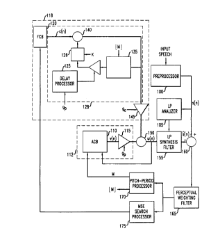
In accordance with the embodiment, an input, speech signal ( 16 bit PCM at 8
kHz
sampling rate) is provided to a preprocessor 100. Preprocessor 100 high-pass
filters the
speech signal to remove undesirable low frequency components and scales the
speech
signal to avoid processing overflow. See 6.729 Draft Section 3.1. The
preprocessed
speech signal, s(n), is then provided to linear prediction analyzer 105. See
6.729 Draft
Section 3.2. Linear prediction (LP) coefficients, a ;, are provided to LP
synthesis
filter 155 which receives an excitation signal, u(n), formed of the combined
output of FCB
and ACB portions of the encoder. The excitation signal is chosen by using an
analysis-by
synthesis search procedure in which the error between the original and
synthesized speech
is minimized according to a perceptually weighted distortion measure by
perceptual
weighting filter 165. See 6.729 Draft Section 3.3.
Regarding the ACB portion 112 of the embodiment, a signal representing the
perceptually weighted distortion (error) is used by pitch period processor 170
to
determine an open-loop pitch-period (delay) used by the adaptive codebook
system 110.
-7- 217 7 414
The encoder uses the determined open-loop pitch-period as the basis of a
closed-loop
pitch search. ACB 110 computes an adaptive codebook vector, v(n), by
interpolating the
past excitation at a selected fractional pitch. See 6.729 Draft Sections 3.4-
3.7. The
adaptive codebook gain amplifier 115 applies a scale factor g p to the output
of the ACB
system 110. See 6.729 Draft Section 3.9.2.
Regarding the FCB portion 118 of the embodiment, an index generated by the
mean squared error (MSE) search processor 175 is received by the FCB system
120 and a
codebook vector, c(n), is generated in response. See 6.729 Draft Section 3.8.
This
codebook vector is provided to the PPF system 128 operating in accordance with
the
present invention (see discussion below). The output of the PPF system 128 is
scaled by
FCB amplifier 145 which applies a scale factor g ~. Scale factor g ~ is
determined in
accordance with 6.729 Draft section 3.9.
The vectors output from the ACB and FCB portions 112, 118 of the encoder are
summed at summer 150 and provided to the LP synthesis filter as discussed
above.
B. 1'he PPF System
As mentioned above, the PPF system addresses the shortcoming of the ACB
system exhibited when the pitch-period of the speech being synthesized is less
than the size
of the subframe and the fixed PPF gain is too large for speech which is not
very periodic.
PPF system 128 includes a switch 126 which controls whether the PPF 128
contributes to the excitation signal. If the delay, M, is less than the size
of the subframe,
L, than the switch 126 is closed and PPF 128 contributes to the excitation. If
M >_ L,
switch 126 is open and the PPF 128 does not contribute to the excitation. A
switch
control signal K is set when M < L. Note that use of switch 126 is merely
illustrative.
Many alternative designs are possible, including, for example, a switch which
is used to
by-pass PPF 128 entirely when M >_ L.
The delay used by the PPF system is the integer portion of the pitch-period,
M, as
computed by pitch-period processor 170. The memory of delay processor 135 is
cleared
prior to PPF 128 operation on each subframe. The gain applied by the PPF
system is
2177414
_g_
provided by delay processor 125. Processor 125 receives the ACB gain, g P, and
stores it
for one subframe (one subframe delay). The stored gain value is then compared
with
upper and lower limits of 0.8 and 0.2, respectively. Should the stored value
of the gain be
either greater than the upper limit or less than the lower limit, the gain is
set to the
respective limit. In other words, the PPF gain is limited to a range of values
greater than
or equal to 0.2 and less than or equal to 0.8. Within that range, the gain may
assume the
value of the delayed adaptive codebook gain.
The upper and lower limits are placed on the value of the adaptive PPF gain so
that the synthesized signal is neither overperiodic or aperiodic, which are
both perceptually
undesirable. As such, extremely small or large values of the ACB gain should
be avoided.
It will be apparent to those of ordinary skill in the art that ACB gain could
be
limited to the specified range prior to storage for a subframe. As such, the
processor
stores a signal reflecting the ACB gain, whether pre- or post-limited to the
specified range.
Also, the exact value of the upper and lower limits are a matter of choice
which may be
varied to achieve desired results in any specific realization of the present
invention.
C. The Decoder
The encoder described above (and in the referenced sections of the 6.729
Draft)
provides a frame of data representing compressed speech every 10 ms. The frame
comprises 80 bits and is detailed in Tables 1 and 9 of the 6.729 Draft. Each
80-bit frame
of compressed speech is sent over a communication channel to a decoder which
synthesizes a speech (representing two subframes) signals based on the frame
produced by
the encoder. The channel over which the frames are communicated (not shown)
may be
of any type (such as conventional telephone networks, cellular or wireless
networks, ATM
networks, etc.) and/or may comprise a storage medium (such as magnetic
storage,
semiconductor RAM or ROM, optical storage such as CD-ROM, etc.).
An illustrative decoder in accordance with the present invention is presented
in
Figure 4. The decoder is much like the encoder of Figure 3 in that it includes
both an
adaptive codebook portion 240 and a fixed codebook portion 200. The decoder
decodes
2117414
-9-
transmitted parameters (see 6.729 Draft Section 4.1 ) and performs synthesis
to obtain
reconstructed speech.
The FCB portion includes a FCB 205 responsive to a FCB index, I, communicated
to the decoder from the encoder. The FCB 205 generates a vector, c(n), of
length equal
to a subframe. See 6.729 Draft Section 4.1.3. This vector is applied to the
PPF 210 of
the decoder. The PPF 210 operates as described above (based on a value of ACB
gain,
g p, delayed in delay processor 225 and ACB pitch-period, M, both received
from the
encoder via the channel) to yield a vector for application to the FCB gain
amplifier 235.
The amplifier, which applies a gain, g ~, from the channel, generates a scaled
version of
the vector produced by the PPF 210. See ,6.729 Draft Section 4.1.4. The output
signal of
the amplifier 235 is supplied to summer 255 which generates an excitation
signal, u(n).
Also provided to the summer 255 is the output signal generated by the ACB
portion 240 of the decoder. The ACB portion 240 comprises the ACB 245 which
generates an adaptive codebook contribution, v(n), of length equal to a
subframe based on
past excitation signals and the ACB pitch-period, M, received from encoder via
the
channel. See 6.729 Draft Section 4.1.2. This vector is scaled by amplifier 250
based on
gain factor, g p received over the channel. This scaled vector is the output
of ACB
portion 240.
The excitation signal, u(n), produced by summer 255 is applied to an LPC
synthesis filter 260 which synthesizes a speech signal based on LPC
coefficients, d ;,
received over the channel. See 6.729 Draft Section 4.1.6.
Finally, the output of the LPC synthesis filter 260 is supplied to a post
processor 265 which performs adaptive postfiltering (see 6.729 Draft Sections
4.2.1 -
4.2.4), high-pass filtering (see 6.729 Draft Section 4.2.5), and up-scaling
(see 6.729 Draft
Section 4.2.5).
II. Discussion
Although a number of specific embodiments of this invention have been shown
and
described herein, it is to be understood that these embodiments are merely
illustrative of
the many possible specific arrangements which can be devised in application of
the
-lo- 2 i l 7 414 .
principles of the invention. Numerous and varied other arrangements can be
devised in
accordance with these principles by those of ordinary skill in the art without
departing
from the spirit and scope of the invention.
For example, should scalar gain quantization be employed, the gain of the PPF
may
be adapted based on the current, rather than the previous, ACB gain. Also, the
values of
the limits on the PPF gain (0.2, 0.8) are merely illustrative. Other limits,
such as 0.1 and
0.7 could suffice.
In addition, although the illustrative embodiment of present invention refers
to
codebook "amplifiers," it will be understood by those of ordinary skill in the
art that this
term encompasses the scaling of digital signals. Moreover, such scaling may be
accomplished with scale factors (or gains) which are less than or equal to one
(including
negative values), as well as greater than one.
2177414
Kroon 4
IVTERV ATIONAL TELECOVI1~ZU~TICATION I~iION
TELEC01~IVIL'VIC ATIOVS STWD ARDIZATION SECTOR
Date: June 1995
Original: E
STUDY GROUP 15 CONTRIBUTION - Q. 12/15
Draft Recommendation 6.729
Coding of Speech at 8 kbit/s using
Conjugate-Structure-Algebraic
Code=Excited Linear-Predictive (CS-ACELP) Coding
June 7, 1995,
version 4.0
:Vote: Until tAfa Recommendation is approved bar tbt IT U, neither the C code
nor tAt
test vectors mill be available from the ITU. To obtain the C aosret code,
contact:
fir. Gerhard Schroeder, R,apporteur SG15/Q.12
Deutsche Telekom AG, Postfach 100003, 64276 Darmstadt, Germany
Phone: +49 615183 3973, Fax: +49 6151837828, Email:
gerhard.schroederC9fz13.fi.dbp.de
11
2117414
Contents
Kroon 4
1 Introduction is
2 16
General
description
of
the
coder
2.1 Encoder . . . . . . . . . . . . . . . . . . . . . l7
. . . . . . . . . . . . . . . . . . . . .
2.2 Decoder . . . . . . . . . . . . . . . . . . . . . 18
. . . . . . . . . . . . . . . . . . . . .
2.3 Delay . . . . . . . . . . . . . . . . . . . . . . 19
. . . . . . . . . . . . . . . . . . . . .
2.4 Speech coder description . . . . . . . . . . . . lg
. . . , , , , , , , . . . , . . . , . . ,
2.5 Yotational conventions . . . . . . . . . . . . . 20
. . . . . . . . . . . . . . . . . . . . .
3 24
1~actioaal
description
of
the
encoder
3.1 Pre-processing . . . . . . . . . . . . . . . . . 24
. . . . . . . . . . . . . . . . . . . . .
3.2 Linear prediction analysis and quaatization . . . 24
. . . . . . . . . . . . . . . . . . .
3.2.1 Windowing and autocorrelation computation . 25
. . . . . . . . . . . . . . . .
3.2.2 Levinson-Durbin algorithm . . . . . . . . . 2g
. . . . . . . . . . . . . . . , , ,
3.2.3 LP to LSP conversion . . . . . . . . . . . 2g
. . . . . . . . . , , , . , , , . . ,
3.2.4 Quantization of the LSP coefficients w. . . 28
. . . . . . . . . . . . . . . . . . .
3.2.5 Interpolation of the LSP coefficients . . . 30
. . . . . . . . . . . . . . . . . . .
3.2.g LSP to LP conversion . . . . . . . . . . . 30
. . . . . . . . . . . . . . . . . . .
3.3 Perceptual weighting . . . . . . . . . . . . . . 31
. . . . . . . . . . . . . . . . . . . . .
3.4 Open-loop pitch analysis . . . . . . . . . . . . 32
. . . . . . . . . . . . . . . . . . . . .
3.5 Computation of the impulse response . . . . . . . 33
. . . . . . . . . . . . . . . . . . .
12
- . 2117414
Kroon 4
_ 3.6 Computation of the target signal . . . . . . . . . . , , , , , , , . , .
, , , , , . . . 34
3.7 :adaptive-codebook search . . . . . . . . . . . . . . . . , , . , , , , ,
, , . . . . . . 34
3.7.1 Generation of the adaptive codebook vector . . . . . . . . . . . . . . .
. . . 36
:3.7.'? Codeword computation for adaptive codebook delays . . - . . . . . . .
. . . 36
3.7.3 Computation of the adaptive-codebook gain . . . . . . . . . . . . . . .
. . . 37
3.8 Fixed codebook: structure and search . . . . . . . . . . . . . . . . . , ,
. , , , , , 3 7
3.8.1 Fixed-codebook search procedure . . . . . . . . . . . . . . . . . . . .
. . . . 38
3.8.2 Codeword computation of the fixed codebook . . . . . . . . . . . . . . .
. . 40
3.9 Quantization of the gains . . . . . . . . . . . . . . . . . . . . . . . .
. . . . . . . . 40
3.9.1 Gain prediction . . . . . . . . . . . . . . . . . . . . . . . . . . . .
. . . . . . 41
3.9.2 Codebook search for gain quantization . . . . : . . . . . . . . . . . .
. . . . 42
3.9.3 Codeword computation for gain quantizer . . . . . . . . . . . . . . . .
. . . 43
3.10 !Memory update . . . . . . . . . . . . . . . . . . . . . . . . . . . . .
. . . . . . . . . 43
3.11 Encoder and Decoder initialization . . . . . . . . . . . . . . . . . . .
. . . . . . . . 43
4 Fhnctional description of the decoder 45
4.1 Parameter decoding procedure . . . . . . . . . . . . . . . . . . . . . . .
. . . . . . 45
4.1.1 Decodins of LP filter parameters . . . . . . . . . . . . . . . . . . . .
. . . . 46
4.1.2 Decoding of the adaptive codebook vector . . . . . . . . . . . . . . . .
. . . 46
4.1.3 Decoding of the fixed codebook vector . . . . . . . . . . . . . . . . .
. . . . 47
4.1.4 Decoding of the adaptive and faced codebook gains . . . . . . . . . . .
. . . 47
4.1.5 Computation of the parity bit . . . . . . . . . . . . . . . . . . . . .
. . . . . 47
13
2117414
Kroon 4
-1.1.6 Computing the reconstructed speech . . . . . 4;
. . . . . . . . . . . . . . . , ,
4.2 Post-processing 48
. . . . . .
. . . . . .
. . . . . .
. . . . . .
. . . . . .
. . . . . .
. .
4.2.1 Pitch postfilter . . . . . . . . . . . . . . 48
. . . . . . . . . . . . . . . . . . . .
4.2.2 Short-term postfilter . . . . . . . . . . . . 4g
. . . . . . , , , , , , , , , , , , .
4.2.3 Tilt compensation . . . . . . . . . . . . . . 49
. . . . . . . . , . , , , . , , _ .
4.2.4 Adaptive gain control . . . . . . . . . . . . 50
. . . . . . . . . . . . . . . . . .
4.2.5 High-pass filtering and up-scaling . . . . . 50
. . . . . . . . . . . . , . . . . . .
4.3 Concealment 51
of frame erasures
and parity errors
. . . . . .
. . . . . .
. . . . . .
.
4.3.1 Repetition of LP filter parameters . . . . . 52
. . . . . . . . . . . . . . . . . .
4.3.2 Attenuation of adaptive and fixed codebook gains52
. . . . . . . . . . . . . .
4.3.3 Attenuation of the memory of the gain predictor 52
. . . . . . . . . . . . . . .
4.3.4 Generation of the replacement excitation . . 52
. . . . . . . . . . . . . . . . .
Bit-exact descriptioa of the CS-ACELP coder 54
5.1 Use of the simulation software . . . . . . . . . . . . . . . . . . . . . .
. . . . . . . . 54
5.2 Organization of the simulation software . . . . . . . . . . . . . . . . .
. . . . . . . 54
14
2i 77414
Kroon ~
- 1 Introduction
This Recommendation contains the description of an algorithm for the coding of
speech signals at 8
kbit/s using Conjugate-Structure-Algebraic-Code-Excited Linear-Predictive (CS-
ACELP) coding.
This coder is designed to operate with a digital signal obtained by first
performing telephone
bandwidth filtering (ITU Rec.6.710) of the analog input signal, then sampling
it at $000 Hz.
followed by conversion to 16 bit linear PCM for the input to the encoder. The
output of the decoder
should be converted back to an analog signal by similar means. Other
input/output characteristics,
such as those specified by ITU Rec. 6.711 for 64 kbit/s PCM data, should be
converted to 16 bit
linear PCM before encoding, or from 1B bit linear PCM to the appropriate
format after decoding.
The bitstream from the encoder to the decoder is defined within this standard.
This Recommendation is organized as follows: Section 2 gives a general outline
of the CS-
ACELP algorithm. In Sections 3 and 4, the CS-ACELP encoder sad decoder
principles are dis-
cussed, respectively. Section 5 describes the software that defines this codet
in 18 bit fixed point
arithmetic.
- 2177414
Kroon 4
_ 2 General description of the coder
The CS-ACELP coder is based on the code-excited linear-predictive (CELP)
coding model. The
coder operates on speech frames of 10 ms corresponding to 80 samples at a
sampling rate of 8000
samples/sec. For every LO cosec frame, the speech signal is analyzed to
extract the parameters of
the CELP model ( LP filter coefficients, adaptive and fixed codebook indices
and gains). These
parameters are encoded and transmitted. The bit allocation of the coder
parameters is shown in
Table 1. At the decoder, these parameters are used to retrieve the excitation
and synthesis filter
Table 1: Bit allocation of the 8 kbit/s CS-ACELP algorithm ( 10 cosec frame).
Parameter Codeurord SubfromeSubJrameTotnl per
1 8 frame
LSP L0, Ll, lg
L2, L3
Adaptive codebookP1, P2 8 5 13
delay
Delay parity PO 1 1
Fixed codebook C1, C2 13 13 26
index
Fixed codebook S1, S2 4 4 8
sign
Codebook gains GA1, GA2 3 3 g
(stage 1)
Codebook gains GBi, GB2 4 4 8
(stage 2)
Total 80
parameters. The speech is reconstructed by filtering this excitation through
the LP synthesis filter,
as is shown in Figure 1. The short-term synthesis filter is based on a 10th
order linear prediction
ourPUr
LOHO-TEFt~I Sf_IORT-TFi~IA ~ SPEECN
FILTERS FILTER FILT'EH
PAWIAIETER OECOOIN3
RECEIVED 81TSTREAwI
Figure 1: Block diagram of conceptual CELP synthesis model.
(LP) filter. The long-term, or pitch synthesis filter is implemented using the
so-called adaptive
codebook approach for delays less thaw the subframe length. After computing
the reconstructed
speech. it is further enhanced by a postfilter.
16
2117414
Krooa 4
2.1 Encoder
The signal flow at the encoder is shown in Figure Z. The input signal is high-
pass filtered and scaled
INPUT
SPEECH
PRE
PROCESSING
LP ANALYSIS
G IINTERPOLATKNd
C
FIXED ~ LpC ~b
- CODEBOOK
SYNTHESIS
GP + FILTER
ADAPTIVE
- COOEBOOK
LPC info
.____......._......... ~ ,
,__...._._...~.. MIALYS18
' ' ' PERCEPTUAL
WEIOHTINO
i
-..__.1__......._.
i _ ~ i
..-...,..~. SEARCH
, ~ ~ i
~ ~ ~
i ~
i ~
.......
GAIN ~_..._..__ PENCODN~ti --~ SEAM
U~~~ -._.______._
LPC kMo
Figure 2: Signal flow at the CS-ACELP encoder.
in the pre-processing block. The pre-processed signal serves as the input
signal for all subsequent
analysis. LP analysis is done once per 10 ms frame to compute the LP filter
coe~cients. These
coefficients are converted to tine spectrum pairs (LSP) sad quantized using
predictive two-stage
vector quantization (VQ) with 18 bits. The excitation sequence is chosen by
using an analysis-
by-synthesis search procedure in which the error between the original and
synthesized speech is
minimized according to a perceptually weighted distortion measure. This is
done by filtering the
17
- 2111414
Kroon 4
error signal with a perceptual weighting filter, whose coefficients are
derived from the unquantized
LP filter. The amount of perceptual weighting is made adaptive to improve the
performance for
input signals with a flat frequency-response.
The excitation parameters (fixed and adaptive codebook parameters) are
determined per sub-
frame of ~ ms (40 samples) each. The quantized and unquantized LP filter
coefficients are used for
the second subframe, while is the first subframe interpolated LP filter
coefficients are used (both
quantized and unquantized). An open-loop pitch delay is estimated once per 10
ms frame based
on the perceptually weighted speech signal. Then the following operations are
repeated for each
subframe. The target signal x(n) is computed by filtering the LP residual
through the weighted
synthesis filter W(r)/A(z). The initial states of these filters are updated by
filtering the error
between LP residual and excitation. This is equivalent to the common approach
of subtracting the
zero-input response of the weighted synthesis filter from the weighted speech
signal. The impulse
response, h(n), of the weighted synthesis filter is computed. Closed-loop
pitch analysis is then
done (to find the adaptive codebook delay and gain), using the target r(n) and
impulse response
h(n), by searching around the value of the open-loop pitch decay. A fractional
pitch delay with 1/3
resolution is used. The pitch delay is encoded with 8 bits is the first
subframe and differentially
encoded with 5 bits in the second subframe. The target signet x(n) is updated
by removing the
adaptive codebook contribution (filtered adaptive codevector), and this new
target, xa(n), is used
in the fixed algebraic codebook search (to find the optimum excitation). An
algebraic codebook
with 17 bits is used for the fixed codebook excitation. The gains of the
adaptive and fixed code-
book are vector quantized with 7 bite, (with MA prediction applied to the
fixed codebook gain).
Finally, the filter memories are updated using the determined excitation
signal.
2.2 Decoder
The signal flow at the decoder is shown in Figure 3. First, the parameters
indices are extracted from
the received bitrtream. These indices are decoded to obtain the coder
parameters corresponding
to a 10 cns speech frame. These parameters are the LSP coefficients, the 2
fractional pitch delays,
the 2 fixed codebook vectors, sad the 2 sets of adaptive and faced codebook
gains. The LSP
coefficients are interpolated and converted to LP filter coefficients for each
subframe. Then, for
each ~0-sample subframe the following steps are done:
~ the excitation is constructed by adding the adaptive and fixed codebook
vectors scaled by
their respective gains,
18
Kroon 4 21 l 7 414
GC
FIXED
COOE800K
SYNTHESIS POST
d FILTER PppCESSING
P
_ ADAPTIVE
CODEBOOK
Figure 3: Signal flow at the CS-ACELP decoder.
~ the speech is reconstructed by filtering the excitation through the LP
synthesis filter,
~ the reconstructed speech signal is passed through a post-processing stage,
which comprises
of an adaptive postfilter based on the long-term and short-term synthesis
filters, followed by
a high-pass filter and scaling operation.
2.3 Delay
This coder encodes speech and other audio signals with 10 ms frames. In
addition, there is a
look-ahead of 5 ms, resulting in a total algorithmic delay of 15 ms. All
additional delays in a
practical implementation of this coder are due to:
~ processing time needed for encoding and decoding operations,
. transmission time on the communication link,
~ multiplexing delay when combining audio data with other data.
2.4 Speech coder description
The description of the speech coding algorithm of this Recommendation is made
in terms of
bit-exact, fixed-point mathematical operations. The ANSI C code indicated in
Section 5, which
constitutes an integral part of this Recommendation, reflects this bit-exact,
fixed-point descriptive
approach. The mathematical descriptions of the encoder (Section 3), and
decoder (Section 4), can
be implemented in several other fashions, possibly leading to a codec
implementation not complying
with this Recommendation. Therefore, the algorithm description of the C code
of Section 5 shall
19
_ _ 2117414
Kroon 4
,.
_ take precedence over the mathematical descriptions of Sections 3 and 4
whenever discrepancies are
found. A non-exhaustive set of test sequences which can be used in conjunction
with the C code
are available from the ITU.
2.5 Notational conventions
Throughout this document it is tried to maintain the following notational
conventions.
~ Codebooks are denoted by caligraphic characters (e.g. C).
~ Time signals ate denoted by the symbol and the sample time index between
parenthesis (e.g.
s(n)). The symbol n is used as sample instant index.
~ Superscript time indices (e.g y~'"~) refer to that variable corresponding to
subframe m.
~ Superscripts identify a particular element in a coefficient array. _
~ A ' identifies a quantized version of a parameter.
~ Range notations are done using square brackets, where the boundaries are
included (e.g.
(O.B, 0.9J).
~ !og denotes a logarithm with base 10.
Table 2 lists the most relevant symbols used throughout this document. A
glossary of the most
Table 2: Glossary of symbols.
Nome ReferonceDescription
1/A(z)Eq. LP synthesis
(2) filter
8m(z)Eq. input high-pass
(1) filter
Es(s)Eq. pitch poathlter
(77)
H~(s)' Eq. short-term postftlter
(83)
gels)Eq. tilt-compensation
(85) filter
Hr~(z)Eq. output high-peas
(90) fillet
P(z) Eq. pitch ftltet
(46)
W(z) Eq. weighting filter
(2T)
relevant signals is given in Table 3. Table 4 summarizes relevant variables
and their dimension.
2i 71414
Kroon 4
Constant parameters are listed in Table i. The acronyms used in this
Recommendation are sum-
marized in Table 6.
Table 3: Glossary of signals.
.Vane Description
h(n) impulse response of weighting
and synthesis filters
r(k) auto-correlation sequence
r'{k) modified auto-correlation
sequence
R(k) correlation sequence
Jw(n) weighted speech signal
s(n) speech signal
~'(n) windowed speech signal
aj(n) postfiltered output
~ j'(n)gain-xaled postfiltered output
.i(n) reconstructed speech signal
r(n) residual signal
s(n) target signal
az(n) second target signal
v(n) adaptive codebook contribution
c(n) fixed codebook contribution
g(n) v(n) s h(n)
z(n) c(n) s h(n)
n(n) excitation to LP synthesis
filter
d(n) correlation between target
signal and h(n)
ew(n) error signal
21
2177414
V,,.. Kroon 4
Table 4: Glossary of variables.
Name SiseDescription
9P 1 adaptive codebook
gain
1 fized codebook gain
90 1 mod'>Tted gain for
pitch pastfilter
9y.e 1 pitch gain for pitch
pastglter
1 gain term short-term
pwtfiltet
9e 1 gain term tilt postfilter
T~ 1 open-loop pitch delay
a; 10 LP coefficients
k; 10 reflection coefttdents
o; 2 LAR coefficients
W, 10 LSF normalized freqneacies
q; 10 LSP coeffiaeats
r(k) 11 correlation coefficients
ur; 10 LSP weighting coefficients
1; 10 LSP qnantizer ontpnt
22
2177414
~".,. Kroon =1
Table i: Glossary of constants.
:VarneValue Description
f, 9000 sampling frequency
fo 60 bandwidth expansion
y 0.94/0.98weight factor perceptual
weighting filter
7z 0.60/(0.4-0.7~weight factor perceptual
weighting filter
Tn 0.55 weight factor post filter
7a 0.70 weight factor post filter
7p 0.50 weight factor pitch post
filter
7s 0.90/0.2 weight factor tilt post
filter
C Table fixed (algebraic) codebook
7
CO Section moving average predictor
3.2.4 codebook
Gl Section Firat stage LSP codebook
3.2.4
G2 Section Second stage LSP codebook
3.2.4 (low put)
C3 Section Second stage LSP codebook
3.2.4 (high part)
Section First stage gain codebook
3.9
~8 Section Second stage gain codebook
3.9
iLlayEq. (B) correlation lag window
~tp Eq. (3) LPC analysis window
Table 8: Glossary of acronyms.
AcronymDescription
CELP code-excited linear-prediction
MA moving average
MSB most significant
bit
LP linear prediction
LSP tine spectral pair
LSF line spectral frequency
VQ vector qnaatization
23
2117414
Eiroon 4
3 ~nctional description of the encoder
In this section we describe the different functions of the encoder represented
in the blocks of
Figure 1.
3.1 Pre-processing
As stated in Section 2, the input to the speech encoder is assumed to be a 16
bit PCM signal.
Two pre-processing functions are applied before the encoding process: 1)
signal scaling, and 2)
high-pass filtering.
The scaling consists of dividing the input by a factor 2 to reduce the
possibility of overflows
in the fixed-point implementation. The high-pass filter serves as a precaution
against undesired
low-frequency components. A second order pole/zero filter with a cutoff
frequency of 140 Ha is
used. Both the scaling and high-pass filtering are combined by dividing the
coe~cients at the
numerator of this filter by 2. The resulting filter is given by
0.46363718 - 0.92724705z-t + 0.46363718z-s
Hht(z) = 1-1.9059465z-t +0.9114024x-s ' (1)
The input signal filtered through Hr,l(z) is referred to as s(n), and will be
used in all subsequent
coder operations.
3.2 Linear prediction analysis and quantization
The short-term analysis and synthesis filters are based on 10th order linear
prediction (LP) filters.
The LP synthesis filter is de$ned as
A(z) = 1 + ~;1 id avz'' , (2)
where a;, i = 1,...,10, are the (quantized) linear prediction (LP)
coefficients. Short-term predic-
tion, or linear prediction analysis is performed once per speech frame using
the autocorrelation
approach with a 30 ms asymmetric window. Every 80 samples (10 ms), the
autocorrelatioa coef&-
cients of windowed speech are computed and converted to the LP coeflscients
using the Levinson
algorithm. Then the LP coefficients are transformed to the LSP domain for
quantization and
interpolation purposes. The interpolated quantized and unquantized filters are
converted back to
the LP filter coefficients (to construct the synthesis and weighting filters
at each subframe).
24
2117414
hroon 4
3.2.1 Windowing and autocorrelation computation
The LP analysis window consists of two parts: the first part is half a Hamming
window and the
second part is a quarter of a cosine function cycle. The window is given by:
0.~4 - 0.46 cos ( 399 ) , n = 0, . . . . 199,
cos ( ~'T~ iss °o y , n = 200, . . . , 239.
There is a ~ ms lookahead in the LP analysis which means that 40 samples are
needed from the
future speech frame. This translates into an extra delay of 5 ms at the
encoder stage. The LP
analysis window applies to 120 samples from past speech frames, 80 samples
from the present
speech frame, and 40 samples from the future frame. The windowing in LP
analysis is illustrated
in Figure 4.
LP WINDOWS
SUBFRAMES
Figure 4: Windowing in LP analysis. The different shading patterns identify
corresponding exci-
tation and LP analysis frames.
The autocortelation coefficients of the windowed speech
s'(n) - wtP(n) s(n), n = 0, . . ., 239, (4)
are computed by
239
r(k) _ ~ s~(n)s~(n - k), : k = 0, . . . ,10, (5)
n=k
To avoid arithmetic problems for low-level input signals the value of r(0) has
a lower boundary of
r(0) = 1Ø A 8tt Hs bandwidth expansion is applied, by multiplying the
autocorrelation coefficients
with
z
tvtos(k)=exp -~ C2~°kl . k-1,...,10, (6)
).
where fo = 60 Hz is the bandwidth expansion and f, = 8000 Hz is the sampling
frequency. Further,
r(0) is multiplied by the white noise correction factor 1.0001, which is
equivalent to adding a noise
Hoor at -40 dB.
_ 2117414
Kroon ~
3.2.2 Levinson-Durbin algorithm
The modified autocorrelation coefficients
r'(0) = 1.0001 r(0)
r~(k) = mra9(k) r(k), k = 1, . . .. 10 (; )
are used to obtain the LP filter coefficients a;, i = 1, . . . , 10, by
solving the set of equations
to
~, a~r~(~i - k~) _ -r'(k), k = 1, .. .,10. (8)
=t
The set of equations is (8) is solved using the Levinson-Durbin algorithm.
This algorithm uses the
following recursion:
E(0) = r~(0)
for i = 1 to 10
a(~_t) - 1
0
k: _ _ [~i=o ai~_t>r'(i _ j), lE(t _ 1) .
a;') = k;
jorj=1 toi-1
aJ') = aJ'-t) + k;a;'_~t)
end
E(i) _ (1 - k?)E(i - 1) , ijE(i) < 0 then E(i) = 0.01
end
The final solution is given as a~ - alto), J = 1, . . . ,10.
3.2.3 LP to LSP conversion
The LP filter coef$cients a;, i = 1, . . ., 10 are converted to the line
spectral pair (LSP) representa-
tion for quantization and interpolation purposes. For a 10th order LP filter,
the LSP coefficients
are defined as the roots of the sum and difference polynomials
Fi(z) _ .4(z) ~- z-mA(z-t)~
and
Fi(z) = A(z) - z m A(z 1), (10)
respectively. The polynomial Fi(z) is symmetric, and F2(s) is antisymmetric.
It can be proven
that all roots of these polynomials'are on the unit circle aad they alternate
each other. Fi(z) has
2B
2177414
Kroon 4
a root z = -1 (;~ = a) and F~(z) has a root z = 1 (w = 0). To eliminate these
two roots, we define
the new polynomials
Ft(z) = Fi(z)/(1+z't), (11)
and
F~(z) - Fz(z)l(1 - ~ t). (12)
Each polynomial has 5 conjugate roots on the unit circle (et~"~), therefore,
the polynomials can
be written as
Ft(z) _ ~ (1 - 2q~z-t + z-z) (13)
i=1,3,...,9
and
Fz(z) _ ~ (1 - 2qiz-t + z'z), (14)
i=2,4,...,10
where q; = cos(w;) with w; being the line spectral frequencies (LSF) and they
satisfy the ordering
property 0 < wt < wz < . . . < wto < a. We refer to q; as the LSP coefficients
in the cosine domain.
Since both polynomials Ft(z) sad Fz(z) are symmetric only the first 5
coefficients of each
polynomial need to be computed. The coefficients of these polynomials are
found by the recursive
relations
ft(i + 1) = a;+t + ato_; - ft(t), i = 0,...,4,
fz(= + 1) = a:+t - ato-i + fz(i), i = 0,...,4, (15)
where ft(O) = fz(0) = 1Ø The LSP coef&cienta are found by evaluating the
polynomials Ft(z)
and Fz(z) at 60 points equally spaced between 0 and a and checking for sign
changes. A sign
change signifies the existence of a root and the sign change interval is then
divided 4 times to
better track the root. The Chebyshev polynomials are used to evaluate Ft(z)
sad Fz(z). In this
method the roots are found directly in the cosine domain {q;}. The polynomials
Ft(z) or Fz(z),
evaluated at z = a?", can be written as
F(w) = 2e'l s"' C(x), ( 16)
with
C(x) = TS(x) + f(1)T4(x) + f(2)T3(x) + f(3)Tz(x) + f(4)Tt(x) + f(5)/2, (17)
where Tm(r) = cos(rnw) is the mth order Chebyshev polynomial, sad f(i), i =
1,...,5, are the
coefficients of either Ft(z) or Fz(z), computed using the equations in (15).
The polynomial C(x)
is evaluated at a certain value of x = cos(w) using the recursive relation:
jor k = 4 downto 1
27
2177414
Kroon 4
bk = 2xbk+i - bk+z + f(5 - k)
end
C(r) _ ~bt - 6= + f (5)/2
with initial values 65 = 1 and bs = 0.
3.2.4 Quantization of the LSP coefficients
The LP filter coefficients are quantized using the LSP representation in the
frequency domain; that
~s
~r; = arccos(q;), i = 1, . . . , 10, ( 18)
where w; are the line spectral frequencies (LSF) in the normalized frequency
domain (0, a). A
switched 4th order VIA prediction is used to predict the current set of LSF
coef&cients. The
difference between the computed and predicted set of coef$cieats is quaatized
using a two-stage
vector quantizer. The first stage is a 10-dimensional VQ using codebook G1
with 128 entries (7
bits). The second stage is a 10 bit VQ which has been implemented as a split
VQ using two
5-dimensional codeboolcs, G2 and C3 containing 32 entries (5 bits) each.
To explain the quantization process, it is convenient to first describe the
decoding process.
Each coef&cient is obtained from the sum of 2 codebooka:
h - G1;(L1)+,C2;(L2) i= 1,...,5, (19)
G1;(L1) + G3~;_s~(L3) i = 8, . . . ,10,
where L1, L2, and L3 are the codebook indices. To avoid sharp resonancea in
the quantized LP
synthesis filters, the coef&cieats l; are arranged such that adjacent
coefficients have a minimum
distance of J. The rearrangement routine is shown below:
fori = 2,...10
~f(t:_~ >r:_J)
r:_~ _ (r: +r:_~ _ J)12
l: _ (r: + l;-~ + J)/2
eal
end
This rearrangement process is executed twice. First with a value of J =
0.0001, then with a value
of J = 0.000095.
After this rearrangement process, the quantized LSF coef&cients ;~;"'1 for the
current frame n,
are obtained from the weighted sum of previous quantizer outputs I~'"-k~, and
the current quantizer
28
2177414
Kroon 4
output hm)
4 4
'aim) _ ~ 1 - ~, mi )!im) '~' ~ m~ !im k)~ ~ - 1. . . .. 10, (20)
k=l k-_1
where mk are the coefficients of the switched V1A predictor. Which J~IA
predictor to use is defined
by a separate bit G0. At startup the initial values of !~k) are given by l; =
ia/11 for all k < 0.
After computing ~;, the corresponding filter is checked for stability. This is
done as follows:
1. Order the coefficient ~; in increasing value,
2. If ~1 < 0.005 then cal = 0.005, '
3. If :v;+1 - ~; < 0.0001, then ~;+1 = ~; + 0.0001 i = 1, . . . ,9,
4. If ~lo > 3.135 then ~lo = 3.135.
The procedure for encoding the LSF parameters can be outlined as follows. For
each of the
two 1dA predictors the beat approximation to the current LSF vector has to be
found. The best
approximation is defined as the one that minimizes a weighted mean-squared
error
to
EtPC = ~ w~(~: -W~)s. (21)
cm
The weights w; are made adaptive as a function of the unquantized LSF
coef$cients,
1.0 if ;~Z - 0.04a - 1 > 0,
wl -
10(~rs - 0.04x - 1)s + 1 otherwise
w; 2 <_ i < 9 _ 1.0 tf ~t+1 - ~~-1 - 1 > 0, (22)
10(x;+1 - ~;-1 - 1)~. + 1 otherwise
1.0 if - w9 + 0.92x - 1 > 0,
wla -
10(-~.i9 + 0.92u - 1)s + 1 otherwise
In addition, the weights ws and w6 are multiplied by 1.2 each.
The vector to be quantized for the current frame is obtained from
1 4
is = ~wiml - ~ mi I(m kl~ /(1- ~ mi ), : = 1, . . .,10. (23)
k=i k-_1
The first codebook G1 is searched and the entry L1 that minimizes the
(unweighted) mean-
squared error is selected. This is followed by a search of the second codebook
G2, which defines
29
_ 2177414
Kroon 4
the lower part of the second stage. For each possible candidate, the partial
vector ;v;, i = 1, . . . , 5
is reconstructed using Eq. (20), and rearranged to guarantee a minimum
distance of 0.0001. The
vector with index L2 which after addition to the first stage candidate and
rearranging, approximates
the lower part of the corresponding target best in the weighted VISE sense is
selected. Using the
selected first stage vector L1 and the lower part of the second stage (L2),
the higher part of
the second stage is searched from codebook C3. Again the rearrangement
procedure is used to
guarantee a minimum distance of 0.0001. The vector L3 that minimizes the
overall weighted RISE
is selected.
This process is done for each of the two 1$A predictors defined by G0, and the
MA predictor
LO that produces the lowest weighted ~fSE is selected.
3.2.5 Interpolation of the LSP coefl3cients
The quantized (and unquantized) LP coefficients are used for the second
subframe. For the ftrst
subftame, the quantized (sad unquaatized) LP coefficients are obtained from
linear interpolation
of the corresponding parameters in the adjacent subframes. The interpolation
is done on the LSP
coefficients in the q domain. Let qi"'~ be the LSP coefficients at the 2nd
subframe of frame m, and
q;'~-1~ the LSP coefficients at the 2nd subframe of the past frame (m - 1).
The (unquantized)
interpolated LSP coefficients in each of the 2 subframes ate given by
Su6 frame 1 : q 1; - 0.5q~'"- t ~ + 0.5q~'"~, i = 1, . . . ,10,
Sub frame 2 : q2; = q;"'~ i = 1, . . . , 10. (24)
The same interpolation procedure is used for the interpolation of the
quantized LSP coefficients
by substituting q; by q; in Eq. (24).
3.2.8 LSP to LP conversion
Once the LSP coe~cients are quantized and interpolated, they are converted
back to LP coefficients
{a;}. The conversion to the LP domain is done as follows. The coefficients of
F1(z) sad FZ(z) are
found by expanding Eqs. (13) and (14) knowing the quantized and interpolated
LSP coefficients.
The following recursive relation is used to compute fl(i), i = 1, . . ., 5,
from q;
fori=1 toy
f1(i) _ -2qZi-i ft(i - 1)+2f1(i -2)
for j = i - 1 dotvnto 1
- . 2177414
hroon 4
- f1(~) = fl(:!) - Z q2i-~ fl (J - 1) + fl(j - Z)
end
end
with initial values fl(0) = 1 and fl(-1) = 0. The coefficients fz(i) are
computed similarly by
replacing q~;_1 by q~;.
Once the coefficients fl(e) and fz(i) are found, Ft(:) and FZ(z) are
multiplied by 1 + ~'1 and
1 - _'1, respectively, to obtain Fi(z) and FZ(z); that is
fi(=) - fi(=) + fi(t - 1), a = 1,...,5,
f2(=) - f2(s) - f2(= - 1), t = 1,...,5. (25)
Finally the LP coefficients are found by
0.5fi(i) + 0.5fz(i), i - 1,...,5, (26)
a; _
0.5fi(i - 5) - 0.5fs(i - 5), i = 6,....,10.
This is directly derived from the relation A(z) _ (Fi(z) + Fa(z))/2, and
because F((z) and F2(z)
are symmetric and antisymmetric polynomials, respectively.
3.3 Perceptual weighting
The perceptual weighting filter is based on the unquantized LP filter
coefficients and is given by
__ A(zl?'t) - 1+~i~lyia;t-'
W (z) A(zl?'~) 1 + ~;__°1 yza;z-'' (27)
The values of yl and ys determine the frequency response of the filter W(z).
By proper adjustment
of these variables it is possible to make the weighting more effective. This
is accomplished by
making yt and ys a function of the spectral shape of the input signal. This
adaptation is done
once per 10 ms frame, but an interpolation procedure for each first subframe
is used to smooth
this adaptation process. The spectral shape is obtained from a 2nd-order
linear prediction filter,
obtained as a by product from the Levinson-Durbin recursion (Section 3.2.2).
The reflection
coefficients E;, are converted to Log Area Ratio (LAR) coef&cients o; by
(1.0+~;) _=1,2. (28)
o; =log(1.0-k;)
These L.~rR coefficients are used for the second subframe. The LAR
coefficients for the first
subftame are obtained through linear interpolation with the LAR parameters
from the previous
31
_ . . 2177414
Kroon 4
frame, and are given by:
Subframe 1 : ol; = O.SOim-11 +0.3o~m~, i = 1,...,2,
Subframt 2 : 02; = o~'"~, i = 1, . .., 2. (29)
The spectral envelope is characterized as being either flat ( flat = 1) or
tilted ( flat = 0). For each
subframe this characterization is obtained by applying a threshold function to
the LAR coefficients.
To avoid rapid changes, a hysteresis is used by taking into account the value
of flat in the previous
subframe (m - 1),
0 if of < -1.74 and os > 0.65 and f lath'"' 1 ~ = 1,
flat~'"~ = 1 if of > -1.52 and oa < 0.43 and flat~'"'1> =0, (30)
f lath"'' 1~ otherwix.
If the interpolated spectrum for a subframe is classified as flat ( flat~"'~ =
1), the weight factors
are set to yl = 0.94 and 7z = 0.6. If the spectrum is classified as tilted ( f
lat~'"> = 0), the value
of 71 is set to 0.98, and the value of ya is adapted to the strength of the
resonances in the'LP
synthesis filter, but is bounded between 0.4 and 0.7. If a strong resonance is
present, the value
of y~ is set closer to the upperbound. Thin adaptation is achieved by a
criterion based on the
minimum distance between 2 successive LSP coefficients for the current
subframe. The minimum
distance is given by
d.nin = mine;+1 - ~i~ _ = 1, . . . , 9. (31)
The following linear relation is used to compute yz:
ys = -8.0 * d",;" t 1.0, and 0.4 < yZ < 0.7 (32)
The weighted speech signal in a subframe is given by
io io
aw(n) = a(n) + ~ a;7ia(n - i) - ~ a;yasw(n - i), n = 0, . . ., 39. (33)
=i t=t
The weighted speech signal sw(a) is used to find an estimation of the pitch
delay in the speech
frame.
3.4 Open-loop pitch analysis
To reduce the complexity of the search for the best adaptive codeboor delay,
the search range is
limited around a candidate delay T~, obtained from an open-loop pitch
analysis. This open-loop
32
2117414
Kroon 4
pitch analysis is done once per frame ( 10 ms). The open-loop pitch estimation
uses the weighted
speech signal sw(n) of Eq. (33), and is done as follows: In the first step, 3
maxima of the correlation
;s
R(k) _ ~ sw(n)sw(n - k) (34)
n =0
ace found in the following three ranges
i 80,
= .
1 .
: .
,
143,
i 40,...,19,
=
2
:
i 20,...,39.
=
3
:
The retained maxima R(t; ), i = 1, . . . , 3, are normalized through
R'(t;)= nRw2'~n-t~), i=1,...,3, (35)
The winner among the three normalized correlations is xlected by favoring the
delays with the
values in the lower range. This is done by weighting the normalized
correlationa corresponding to
the longer delays. The best open-loop delay T~ is determined ae follows:
T~ = t 1
R'(?'oP) = R'(ti)
ij R'(tz) > 0.85R'(T~)
R~(ToP) _ ~(tz)
Top = t Z
end
ij R'(t3) > 0.85R'(T~)
R~(T~P) _ ~(t3)
ToP = f3
ead
This procedure of dividing the delay range into 3 sections and favoring the
lower actions is
uxd to avoid choosing pitch multiples.
3.5 Computation of the impulse response
The impulse response, h(n), of the weighted synthesis filter W(z)/A(z) is
computed for each
subframe. This impulx response is needed for the xarch of adaptive and fixed
codebooks. The
impulse response h(n) is computed by filtering the vector of coefficients of
the filter A(z/yl)
extended by zeros through the two filteta 1/A(z) and 1/A(z/7z).
33
2171414
Kroon 4
3.6 Computation of the target signal
The target signal x(n) for the adaptive codebook search is usually computed by
subtracting the
zero-input response of the weighted synthesis filter W(z)/A(z) =
A(z/71)/(.4(z)A(z/y2)] from the
weighted speech signal szv(n) of Eq. (33). This is done on a subframe basis.
An equivalent procedure for computing the target signal, which is used in this
Recommendation,
is the filtering of the LP residual signal r(n) through the combination of
synthesis filter 1/.4(z)
and the weighting filter A(z/yl)/A(z/y2). After determining the excitation for
the subframe, the
initial states of these filters are updated by filtering the difference
between the LP residual and
excitation. The memory update of these filters is explained in Section 3.10.
The residual signal r(n), which is needed for finding the target vector is
also used in the adaptive
codebook search to extend the past excitation buffer. This simplifies the
adaptive codebook search
procedure for delays less than the subframe sine of 40 as will be explained in
the next section. The
LP residual is given by '
io
r(n) = s(n) + ~ ais(n - i), n = 0,...,39. (38)
iol
3.7 Adaptive-codebook search
The adaptive-codebook parameters (or pitch parameters) are the delay and gain.
In the adaptive
codebook approach for implementing the pitch filter, the excitation is
repeated foe delays less than
the subframe length. Ia the search stage, the excitation is extended by the LP
residual to simplify
the closed-loop search. The adaptive-codebook search is done every (5 ms)
subframe. In the first
subframe, a fractional pitch delay Ti is used with a Fesolution of 1/3 in the
range [19~, 843] and
integers only in the range (85, 143). For the second subframe, a delay TZ with
a resolution of 1/3
is always used in the range ((ist)Tl - 5~, (int)Ti + 43], where (int)Ti is the
nearest integer to
the fractional pitch delay Tl of the first subfraciie. Thin range is adapted
for the cases where Ti
straddles the boundaries of the delay range.
For each subframe the optimal delay is determined using closed-loop analysis
that minimizes
the weighted mean-squared error. In the first subframe the delay Tl is found
be searching a small
range (6 samples) of delay values around the open-loop delay T~ (see Section
3.4). The search
boundaries tmi" and tm~ are defined by
train = Top - 3
34
- - 2111414
Kroon 4
tf train-< 20 thin tm;n = 20
tmas = train + 6
if t",~ > 143 them
tmas = 143
train = tmas - s
end
For the second subframe, closed-loop pitch analysis is done around the pitch
selected in the first
subframe to find the optimal delay TZ. The search boundaries are between train
- 3 and tma= + 3 ,
where tm;n and tma= are derived from Ti as follows:
train = (iAt)Tl - 5
tf train < 20 the~i tm;n = 20
tmas = train + 9
~f tmar > 143 then
tmas = 143
train = tmas - 9
end
The closed-loop pitch search minimizes the mean-squared weighted error between
the original
and synthesized speech. This is achieved by maximizing the term
R(k) _ ~n9 o x(n)yk(n)
(37)
~n9 o y~(n)ytr(n)
where r(n) is the target signal and yk(n) is the past filtered excitation at
delay k (past excitation
convolved with h(n)). :Vote that the search range is limited around a
preselected value, which is
the open-loop pitch T~ for the first subframe, and Ti for the second subframe.
The convolution yk(n) is computed for the delay t,~;n, and far the other
integer delays in the
search range k = tm;,; + 1, . . . , t",~, it is updated using the recursive
relation
y~(n) = yx_1(n - 1) + u(-k)h(n), n - 39, . . ., 0, (38)
where u(n), n = -143, . .., 39, is the excitation buffer, and yk_1(-1) = 0.
Note that in the search
stage, the samples u(n), n = 0, . . . , 39 are not known, and they are needed
for pitch delays less
than 40. To simplify the search, the LP residual is copied to u(a) to make the
relation in Eq. (38)
valid for all delays.
For the determination of Ta, and Ti if the optimum integer closed-loop delay
is less than 84,
the fractions around the optimum integer delay have to be tested. The
fractional pitch search
is done by interpolating the normalized correlation in Eq. (37) and searching
for its maximum.
2171414
Kroon ~
The interpolation is done using a EIR filter bl~ based on a Hamming windowed
sine function with
the sinc truncated at tll and padded with aeros at t12 (bi=(12) = 0). The
filter has its cut-off
frequency (-3dB) at 3600 Hz in the oversampled domain. The interpolated values
of R(k) for the
fractions -~, -3, 0, 3, and ~ are obtained using the interpolation formula
3 3
R( k)~ _ ~ R(k - i)61~(t + i.3) + ~ R(k + 1 + e)bl~(3 - t + i.3), t = 0, 1, 2,
(39)
c=a .-_o
where t = 0, 1, 2 corresponds to the fractions 0. 3, and 3, respectively. Yore
that it is necessary
to compute correlation terms in Eq. (37) using a range t",;" - 4, t",as + 4,
to allow for the proper
interpolation.
3.7.1 Generation of the adaptive codebook vector
Once the noninteger pitch delay has been determined, the adaptive codebook
vector v(n) is com-
puted by interpolating the past excitation signal u(n) at the given integer
delay k and fraction
t
9 g
v(n) _ ~ u(n-k+i)b30(t+i.3)+~ u(n-k+1+i)630(3-t+i.3), n = 0,..., 39, t = 0,1,
2.
t=o c=o
(40)
The interpolation filter 630 la based on a Hamming windowed sine functions
with the sine truncated
at t29 and padded with zeros at f30 (630(30) = 0). The filters has a cut-off
frequency (-3 dB) at
3600 Ha in the oversampled domain.
3.7.2 Codeword computation for adaptive codebook delays
The pitch delay Ti is encoded with 8 bits in the first subframe and the
relative delay in the second
subframe is encoded with 5 bits. A fractional delay T is represented by its
integer part (int)T,
and a fractional part jrac/3, frac - -1, 0,1. The pitch index P1 is now
encoded as
((int)Tl - 19) * 3 + jrac - 1, i j Ti = (19, ..., 85J, jruc = (-1, O,1J (41)
P1=
((int)Ti - 85) + 197, i j Ti = (88, ...,143J, jrac = 0
The value of the pitch delay TZ is encoded relative to the value of Tl. Using
the same interpre-
tation as before, the fractional delay TZ represented by its integer part
(in!)TZ, and a fractional
part jrac/3, jrac = -1, 0, 1, is encoded as
P2 = ((int)TZ - t",;" ) * 3 + jrac + 2 (42)
36
2117414
Kroon 4
where t",in is derived from Tl as before.
To make the coder more robust against random bit errors, a parity bit PO is
computed on the
delay index of the first subframe. The parity bit is generated through an XOR
operation on the
6 most significant bits of P1. At the decoder this parity bit is recomputed
and if the recomputed
value does not agree with the transmitted value, an error concealment
procedure is applied.
3.T.3 Computation of the adaptive-codebook gain
Once the adaptive-codebook delay is determined, the adaptive-codebook gain gP
is computed as -
- ~"9 ° l(n)~n) bounded by 0 < gp < 1.2, (43)
gP ~~=o y(n)Y(n)
where y(a) is the filtered adaptive codebook vector (zero-state response of
W(z)/A(z) to v(n)).
This vector is obtained by convolving v(n) with h(n)
y(n) _ ~ v(i)b(n - _) n = 0,...,39. (44)
=o
Yote that by maximizing the term in Eq. (37) in moat cases gp > 0. Ia cane the
signal contains
only negative correlations, the value of gP is set to 0.
3.8 Fixed codebook: structure and search
The fixed codebook is based on an algebraic codebook structure using as
interleaved single-pulse
permutation (ISPP) design. In this codebook, each codebook vector contains 4
non-zero pulses.
Each pulse can have either the amplitudes +1 or -1, and can assume the
positions given in Table 7.
The codebook vector c(n) is constructed by taking a zero vector, and putting
the 4 unit pulses
at the found locations, multiplied with their corresponding sign.
c(n) = a0 b(n - i0) + al b(n - il) + a2 b(n - i2) + a3 b(n - i3), n =
0,...,39. (45)
where a(0) is a unit pulse. A special feature incorporated in the codebook is
that the selected code-
book vector is filtered through an adaptive pre-filter P(z) which enhances
harmonic components
to improve the synthesized speech quality. Here the filter
P(z) - 1/(1- dz'T ) (46)
37
2117414
Kroon 4
Table 7: Structure of fixed codebook C.
PulseSignPositions
i0 s0 0, ~, 10, 15,
20, 25, 30, 35
il sl 1, 6, 11, 16,
21, 26, 31, 36
i2 s2 2, 7, 12, 17,
22, 27. 32, 37
i3 s3 3, 8, 13, 18,
23, 28, 33, 38
4, 9, 14, I9,
24, 29, 34, 39
is used, where T is the integer component of the pitch delay of the current
subframe, and p is a
pitch gain. The value of p is made adaptive by using the quantiaed adaptive
codebook gain from
the previous subframe bounded by 0.2 and 0.8.
,3 = yp'"-1~, 0.2 < p < 0.8. (47)
This filter enhances the harmonic structure for delays less than the subframe
sine of 40. This
modification is incorporated in the fixed codebook search by modifying the
impulse response h(n),
according to
h(n) = h(n) + ~?h(n - T), n = T, .., 39. (48)
3.8.1 Fixed-codebook search procedure
The fixed codeboolt is searched by minimi2ing the mean-squared error between
the weighted input
speech sw(n) of Eq. (33), and the weighted reconstructed speech. The target
signal used is the
closed-loop pitch search is updated by subtracting the adaptive codebook
contribution. That is
as(n) = s(n) - gpy(n), , n = 0,...,39, (~9)
where y(n) is the filtered adaptive codebook vector of Eq. (44).
The matrix 8 a defined as the lower triangular Toeplia convolution matrix with
diagonal h(0)
and lower diagonals h(1), . . ., h(39). If c~ is the algebraic codevector at
index k, then the codebook
is searched by maximising the term
C,E = (~n9 0 d(n)Ck(n))2 (50)
li'b Ck ~Ck ,
where d(n) is the correlation between the target signal sz(n) and the impulse
response h(n), and
~ = H'H is the matrix of correlations of h(n). The signet d(n) and the matrix
~ are computed
38
2177414
,~ Kroon 4
before the codebook search. The elements of d(n) are computed from
39
d(n) _ ~ a(i)h(i - n), n - 0, . . . , 39, (5i)
t=n
and the elements of the symmetric matrix ~ are computed by
39
m(t,J) _ ~ h(n - i)h(n -j). (j >- i)~ (p2)
n=j
Yote that only the elements actually needed are computed and an efficient
storage procedure
has been designed to speed up the search procedure.
The algebraic structure of the codebook C allows for a fast search procedure
since the codebook
vector ek contains only four nonzeco pulses. The correlation in the numerator
of Eq. (50) for a
given vector ck is given by
3
C = ~ a:d(m; ), (53)
c=o
where m; is the position of the ith pulse and a; is its amplitude. The energy
in the denominator
of Eq. (50) is given by
3 Z 3
E = ~ ~(m;, m;) + 2 ~ ~ a;a~~(m:, mi)~ (54)
i=o ~=o ~=:+t
To simplify the search procedure, the pulse amplitudes are predetermined by
quantizing the
signal d(n). This is done by setting the amplitude of a pulse at a certain
position equal to the
sign of d(n) at that position. Befote the codebook search, the following steps
are done. First, the
signal d(n) is decomposed into two signals: the absolute signal d'(n) _ ~d(n)~
and the sign signal
sign(d(n)~. Second, the matrix ~ is modified by including the sign
information; that is,
~'(i, j) = sign (d(i)J sign(d( j)~ ø,(i, j), i = 0, . . . , 39, j = i, . . . ,
39. (55)
To remove the factor 2 in Eq. (54)
~'(i,i) = 0.5ø(i,i), i = 0,...,39. (56)
The correlation in Eq. (53) is now given by
C = ~(mo) + d~(mi ) + d~(ma) + d'(ms), (57)
and the energy in Eq. (54) is given by
- ~~(mo, mo)
39
Kroon 4 217 7 414
+ m'(mt, mt) +~'(mo, mt)
+ 9'(m2, m2) ~' ~'(mo, m?) + O'(mt, m?)
+ m'(m3, m3) + ~~(m0, ma) + ~'(mt, ms) + ~'(m2, m3)~ (a8)
~ focused search approach is used to further simplify the search procedure. In
this approach a
precomputed threshold is tested before entering the last loop, and the loop is
entered only if this
threshold is exceeded. The maximum number of times the loop can be entered is
fixed so that a
low percentage of the codebook is searched. The threshold is computed based on
the correlation
C. The maximum absolute correlation and the average correlation due to the
contribution of the
first three pulses, mar3 and av3, are found before the codebook search. The
threshold is given by
thr3 - av3 + K3(max3 - av3).
The fourth loop is entered only if the absolute correlation (due to three
pulses) exceeds thr3, where
0 < K3 < 1. The value of K3 controls the percentage of codebook search and it
is set here to 0.4.
Yore that this results in a variable search time, and to further control the
search the numbei of
times the last loop is entered (for the 2 subframes) cannot exceed a certain
maximum, which is set
here to 180 (the average worst case per subframe is 90 times).
3.8.2 Codeword computation of the fixed codebook
The pulse positions of the pulses i0, il, and i2, are encoded with 3 bits
each, while the position of
i3 is encoded with 4 bits. Each pulse amplitude is encoded with 1 bit. This
gives a total of 17 bite
for the 4 pulses. By defining s = 1 if the sign is positive and s = 0 is the
sign is negative, the sign
codeword is obtained from
S=s0+2*al+4~a2+8*a3 (60)
and the fixed codebook codeword is obtained from
C = (i0/5) + 8 * (il/5) + 64 * (i2/5) + 512 * (2 * (i3/5) + jz) (61)
where jx - 0 if i3 = 3, 8, .., and js = 1 if i3 = 4, 9,
3.9 Quantization of the gains
The adaptive-codebook gain (pitch gain) and the fixed (algebraic) codebook
gain are vector quan-
tized using 7 bits. The gain codebook search is done by minimizing the mean-
squared weighted
2117414
Kroon 4
error between original and reconstructed speech which is given by
E = x'x + gpy'y + g~z'z - 2gpx'y - 2g~x'z + 2gpg~y'z, (62)
where x is the target vector (see Section 3.6), y is the filtered adaptive
codebook vector of Eq. (44),
and z is the fixed codebook vector convolved with h(n),
n
~(n) _ ~ c(i)h(n - i) n = 0, . . . , 39. (63)
=o
3.9.1 Gain prediction
The fixed codebook gain g~ can be expressed as
9e = ';'9e,
(64)
where g~ is a predicted gain based on previous fixed codebook energies, and y
is a correction factor.
The mean energy of the fixed codebook contribution is given by '
1 39 1
E = 10 log ~4~ ~ cZJ . (65)
=o
after scaling the vector c; with the fined codebook gain g~, the energy of the
scaled fixed codebook
is given by 201ogg~ + E. Let E~'") be the mean-removed energy (in dB) of the
(scaled) fixed
codebook contribution at subframe m, gives by
E~'") = 20 logge + E - E, (66)
where E = 30 dB is the mean energy of the fixed codebook excitation. The gain
g~ can be expressed
as a function of E~"'~, E, and E by
9~ = 1O1~~A'+E-E)~ao.
(67)
The predicted gain g'~ is found by predicting the log-energy of the current
fixed codebook
contribution from the log-energy of previous fixed codebook contributions. The
4th order MA
prediction is done as follows. The predicted energy is given by
4
~"') _ ~ bcRl"'''), (68)
where (bt 62 63 b4) _ (0.68 0.58 0.34 0.19 are the MA prediction coeflicients,
and R~'") is the
quantized version of the prediction error R~"') at subframe m, defined by
R~'") = E~'") - y'"~. (69)
41
2117414
Kroon 4
w
The predicted gain g~ is found by replacing E~'"~ by its predicted value in Eq
(6i ).
9~ = 10~E~m+~_E)/ZO, i0
( )
The correction factor 7 is related to the gain-prediction error by
~"'> = E.~'"~,- E.~'"~ = 20 log(?') ( i 1 )
3.9.2 Codebook search for gain quaatization
The adaptive-codebook gain, gP, sad the factor y are vector quantized using a
2-stage conjugate
structured codebook. The first stage consists of a 3 bit two-dimensional
codebook G.4, and the
second stage consists of a 4 bit two-dimensional codebook ~B. The first
element in each codebook
represents the quantized adaptive codebook gain gp, and the second element
represents the quan-
tized fixed codebook gain correction factor 7. Given codebook indices m and n
for Q.4 and ~B,
respectively, the quantized adaptive-codebook gain is given by
yp = ~r41(m) +~Bt(n), (72)
and the quaatized fixed-codebook gain by
9a = 9e ?' = 9e (~AZ(m) + ~BZ(n)). (73)
This conjugate structure simplifies the codebook search, by applying a pre-
selection process.
The optimum pitch gain gP, and fixed-codebook gain, g~, are derived from Eq.
(62), and are used for
the pre-selection. The codebook art contains 8 entries in which the second
element (corresponding
to g~) has in general larger values than the first element (corresponding to
gP). This bias allows
a pre-selection using the value of y~. In this pre-selection process, a
cluster of 4 vectors whose
second element are close to ga, when g:~ is derived from g~ and gp. Similarly,
the codebook
QB contains 18 entries in which have a bias towards the first element
(corresponding to gp). A
cluster of 8 vectors whose first elements are close to gp are selected. Hence
for each codebook
the best 50 96 candidate vectors ate selected. This is followed by an
exhaustive search over the
remaining 4 * 8 = 32 possibilities, such that the combination of the two
indices minimizes the
weighted mean-squared error of Eq. (62).
~2
2117414
Kroon 4
- 3.9.3 Codeword computation for gain quantizer
The codewords GA and GB for the gain quantizer are obtained from the indices
corresponding to
the best choice. To reduce the impact of single bit errors the codebook
indices are mapped.
3.10 Memory update
An update of the states of the synthesis and weighting filters is needed to
compute the target signal
in the next subframe. After the two gains are quantized, the excitation
signal, u(n), in the present
subframe is found by
u(n) = gpv(n) + yc(n), n = 0,...,39, (74)
where gP and y~ are the quantized adaptive and fixed codebook gains,
respectively, v(n) the adaptive
codebook vector (interpolated past excitation), and c(n) is the fixed codebook
vector (algebraic
codevector including pitch sharpening). The states of the filters can be
updated by filtering-the
signal r(n) - u(n) (difference between residual and excitation) through the
filters 1/A(z) and
A(z/yl)/A(z/y2) for the 40 sample subframe and saving the states of the
filters. This would
require 3 filter operations. A simpler approach, which requires only one
filtering is as follows.
The local synthesis speech, a(n), is computed by filtering the excitation
signal through 1/.4(z).
The output of the filter due to the input r(n) - u(n) is equivalent to e(n) =
s(n) - s(n). So the
states of the synthesis filter 1/A(z) are given by e(n), n = 30, . . ., 39.
Updating the states of the
filter A(z/71 )/A(z/72) can be done by filtering the error signal e(n) through
this filter to find the
perceptually weighted error ew(n). However; the signal eur(n) can be
equivalently found by
ew(n) = x(n) - gpy(n) + 9~z(n)~ (75)
Since the signals s(n), y(n), and z(n) are available, the states of the
weighting filter are updated
by computing eur(n) as is Eq. (75) for n = 30, . . . , 39. This saves two
filter operations.
3.11 Encoder and Decoder initialization
All static encoder variables should be initialized to 0, except the variables
listed in table 8. These
variables need to be initialized for the decoder as well.
43
2117414
Kroon 4
Table 8: Description of parameters with nonzero initialization.
VariableReferenceInitial
vaae
;3 Section 0.8
3.8
t; Section ix/11
3.2.4
q; Section 0.9595,
3.2.4 ..,
l~y~ Section -14
3.9.1
44
. _ 2117414
Kroon 4
4 functional description of the decoder
The signal flow at the decoder was shown in Section 2 (Figure 3). First the
parameters are decoded
(LP coef$cients, adaptive. codebook vector, fixed codeboo~ vector, and gains).
These decoded
parameters are used to compute the reconstructed speech signal. This process
is described in
Section 4.1. This reconstructed signal is enhanced by a post-processing
operation consisting of a
postfilter and a high-pass filter (Section 4.2). Section 4.3 describes the
error concealment procedure
used when either a parity error has occurred, or when the frame erasure flag
has been set.
4.1 Parameter decoding procedure
The transmitted parameters are listed in Table 9. At startup all static
encoder variables should be
Table 9: Description of transmitted parameters indices. The bitstream ordering
is reflected by the
order in the table. For each parameter the moat significant bit (MSH) is
transmitted first.
SymbolDescription Biti
LO Switched predictor index 1
of LSP qnantiser
L1 First stage vector of LSP 7
qnantizes
L2 Secoad stage lower vector 5
of LSP qnantiset
L3 Second stage higher vector 5
of LSP qnantizer
P1 Pitch delay 1st subframe 8
PO Parity bit for pitch 1
S1 Signs of pnlxa 1st snbframe4
C1 Fixed codebook 1st snbfrsme13
GAl Gain codebook (stage 1) 3
1st subframe
GBl Gala codebook (stage 2) 4
lat subfrsme
P2 Pitch delay tad snbframe 5
S2 Signs of palace 2nd subframe4
C2 Fixed codebook tad subframe13
GA2 Gain codebook (stage 1) 3
tad snbframe
GB2 Gain codebook (stage 2) 4
2nd snbframe
initialized to 0, except the variables listed in Table 8. The decoding process
is done in the following
order:
- - 2177414
Kroon 4
- 4.1.1 Decoding of LP filter parameters
The received indices L0, L1, L2, and L3 of the LSP quantizer are used to
reconstruct the quan-
tized LSP coefficients using the procedure described in Section 3.2.4. The
interpolation procedure
described in Section 3.2.5 is used to obtain 2 interpolated LSP vectors
(corresponding to 2 sub-
frames). Eor each subframe, the interpolated LSP vector is converted to LP
filter coefficients a;,
which are used for synthesizing the reconstructed speech in the subframe.
The following steps are repeated for each subframe:
1. decoding of the adaptive codebook vector,
2. decoding of the fixed codebook vector,
3. decoding of the adaptive and fixed codebook gains,
4. computation of the reconstructed speech, -
4.1.2 Decoding of the adaptive codebook vector
The received adaptive codebook index is used to find the integer and
fractional pacts of the pitch
delay. The integer part (int)Ti and fractional part frac of Tl are obtained
from P1 as follows:
if P1 < 197
(int)Ti = (P1+2)/3 + 19
fruc = P1 - (int)Ti*3 + 58
else
(int)Tl = P1 - 112
frac = 0
end
The integer and frattionsl part of TZ are obtained from P2 and train, when
train is derived
from P1 as follows
train = (=~t)Ti - S
if train < 20 tAes tm;n - 20
tmas = train + 9
if t",as > 14$ theft
tmas = 14$
train = tmas - 9
end
46
. 2177414
Kroon 4
Yow TZ is obtained from
(int)TZ = (P2+2)/3 -1 + t",;"
f rac = P2 -2 - ((P2+2)/3 -1)*3
The adaptive codebook vector v(n) is found by interpolating the past
excitation u(n) (at the
pitch delay) using Eq. (40).
4.1.3 Decoding of the fixed codebook vector
The received fixed codebook index C is used to extract the positions of the
excitation pulses. The
pulse signs are obtained from S. Once the pulse positions and signs are
decoded the fixed codebook
vector c(n), can be constructed. If the integer part of the pitch delay, T, is
less than the subframe
size 40, the pitch enhancement procedure is applied which modifies c(n)
according to Eq. (48).
4.1.4 Decoding of the adaptive and ftxed codebook gains
The received gain codebook index gives the adaptive codebook gain yp and the
fixed codebook
gain correction factor y. This procedure is described in detail in Section
3.9. The estimated fixed
codebook gain y~~ is found using Eq. (70). The faced codebook vector is
obtained from the product
of the quantized gain correction factor with this predicted gain (Eq. (B4)).
The adaptive codebook
gain is reconstructed using Eq. (72).
4.1.5 Computation of the parity bit
Before the speech is reconstructed, the parity bit is recomputed from the
adaptive codebook delay
(Section 3.7.2). If this bit is not identical to the transmitted parity bit
P0, it is likely that bit
errors occurred during transmission and the error concealment procedure of
Section 4.3 is used.
4.1.6 Compntiag the recoastructed speech
The excitation u(n) at the input of the synthesis filter (see Eq. (74)) is
input to the LP synthesis
filter. The reconstructed speech for the subframe is given by
io
s(n) = u(n) - ~ a;S(n - i), n - 0,...,39. (76)
t=i
47
- - 2177414
Kroon 4
where d; are the. interpolated LP filter coefficients.
'The reconstructed speech s(n) is then processed by a post processor which is
described in the
next section.
4.2 Post-processing
Post-processing consists of three functions: adaptive postfilteriag, high-pass
filtering, and signal
up-scaling. The adaptive postfilter is the cascade of three filters: a pitch
postfilter Hp(z), a
short-term postfilter H~(z), and a tilt compensation filter H~(z), followed by
an adaptive gain
control procedure. The postfilter is updated every subframe of 5 ms. The
postfiltering process
is organized as follows. First, the synthesis speech s(n) is inverse filtered
through .4(z/y") to
produce the residual signal r(n). The signal r(n) is used to compute the pitch
delay T and gain
9p:e. The signal r(n) is filtered through the pitch postfilter Hp(z) to
produce the signal r'(n) which,
in its turn, is filtered by the synthesis filter 1/(gtA(z/7d)]. FinaUy, the
signal at the output of
the synthesis filter 1/(g~.~(z/ya)] is passed to the tilt compensation filter
Ht(z) resulting in the
postfiltered synthesis speech signal a f (n). Adaptive gain controle is then
applied between a f (n)
and s(n) resulting in the signal af'(n). The high-pass filtering and scaling
operation operate on
the postfiltered signal af'(n).
4.2.1 Pitch postfilter
The pitch, or harmonic, postfilter is given by
_ 1 _
Hp(z) 1 + go(1 + goz T), {i7)
where T is the pitch delay and ga ie a gain factor given by
90 =?'pgpit, (78)
where gp;~ is the pitch gain. Both the pitch delay and gain are determined
from the decoder output
signal. Yote that gp;= is bounded by 1, and it is set to zero if the pitch
prediction gain is less that
3 dB. The factor ~P controls the amount of harmonic postfiltering and has the
value yP = 0.5. The
pitch delay and gain are computed from the residual signal r(n) obtained by
filtering the speech
s(n) through .~(z/y"), which is the numerator of the short-term postfilter
(see Section 4.2.2)
io
r(n) - s(n) + ~ y,',d;s(n - i). (79)
cm
48
2177414
hroon 4
The pitch delay is computed using a two pass procedure. The first pass selects
the best integer To
in the range.(Tl - 1,T1 + 1J, where Tl is the integer part of the
(transmitted) pitch delay in the
first subframe. The best integer delay is the one that maximizes the
correlation
39
R(k) _ ~ r(n)r(n - k). (80)
n-_0
The second pass chooses the best fractional delay T with resolution 1/8 around
To. This is done
by finding the delay with the highest normalized correlation.
L. n9 0 r(n)rk(n)
(81)
~n9 0 rk(n)rk(n)
where rk(n) is the residual signal at delay k. Once the optimal delay T is
found, the corresponding
correlation value is compared against a threshold. If R'(T) < 0.5 then the
harmonic postfiltet is
disabled by setting gp;t = 0. Otherwise the value of gp;~ is computed from:
gp;e = Ln9 o r( ) k(n) bounded b 0 <
~na o Tk(n)Tk(n) ~ Y 9p~e < 1Ø (82)
The noninteger delayed signal rk(n) is first computed using an interpolation
filter of length 33.
after the selection of T, rk(n) is recomputed with a longer interpolation
filter of length 129. The
new signal replaces the previous one only if the longer filter increases the
value of R'(T).
4.2.2 Short-terns postfllter
The short-term postfilter is given by
H!(z) = 1 .4(z/7n) = 1 1 + ~lo y~~z_; 83
9! ~4(z/7e) g1 1 + ~~=1 y'ea:z ' ~ ( )
where .9(z) is the received quantized LP inverse filter (LP analysis is not
done at the decoder),
and the factors 7n and yd control the amount of short=term poetfiltering, and
ate set to ~" = 0.53,
and 7d = 0.7. The gain term gj is calculated on the truncated impulse
response, h~(n), of the
filter A(z/y")jA(z/7d) and given by
19
9l = ~ Iht(n)I~ (84)
n.0
4.2.3 Tilt compensation
Finally, the filter H~(z) compensates for the tilt in the short-term post$lter
H~(z) and is given by
Hi(z) = 1 (1+ytklz-1), (85)
9s
49
- 2111414
f~roon 4
- where yiki is a tilt factor, kl being the ftrst reflection coefficient
calculated on h~(n) with
~,h( 1) l9-i
k1 = -rh(0) ~ r''(:) _ ~ h!(J)hl (l + i). (86)
~ -_o
The gain term gt = 1 - ~ysky compensates for the decreasing effect of g~ in
Hf(z). Furthermore,
it has been shown that the product filter H~(z)Ht(z) has generally no gain.
Two values for y= are used depending on the sign of kl. If kl is negative, yi
= 0.9, and if kt is
positive, yi = 0.2.
4.2.4 Adaptive gain control
Adaptive gain control is used to compensate for gain differences between the
reconstructed speech
signal s(n) and the postfiltered signal sf(n). The gain scaling factor G for
the present subframe
is computed by
G = ~n9 0 ~$(n)~ ..
L..ncO ~8f(n)~. (87)
The gain-scaled postfiltered signal sf'(n) is given by
$f~(n)=g(n)af(n), n=0,...,39, (88)
where g(n) is updated on a sample-by-sample basis and given by
g(n) = 0.85g(n - 1) + 0.15 G, n = 0,...,39. (89)
The initial value of g(-1) = 1Ø
4.2.5 High-peas filtering and up-scaling
A high-pass filter at a cutoff frequency of 100 Hz is applied to the
reconstructed and postfiltered
speech sf'(n). The filter is given by
_ 0.93980581- 1.8795834z-1 + 0.93980581z-s
Hhs(z) 1 - 1.93307352-t + 0.93589199z-~
L'p-scaling consists of multiplying the high-pass filtered output by a factor
2 to retrieve the
input signal level.
~0
2171414
Kroon ~
4.3 Concealment of frame erasures and parity errors
An error concealment procedure has been incorporated in the decoder to reduce
the degradations
in the reconstructed speech because of frame erasures or random errors in the
bitstream. This error
concealment process is functional when either i) the frame of coder parameters
(corresponding to
a 10 ms frame) has been identified as being erased, or ii) a checksum error
occurs on the parity
bit for the pitch delay index P1. The latter could occur when the bitstream
has been corrupted
by random bit errors.
If a parity error occurs on P1, the delay value Ti is set to the value of the
delay of the previous
frame. The value of Tz is derived with the procedure outlined in Section
4.1.2, using this new value
of Tl. If consecutive parity errors occur, the previous value of T~,
incremented by 1, is used.
The mechanism for detecting frame erasures is not defined in the
Recommendation, and will
depend on the application. The concealment strategy has to reconstruct the
current frame, based
on previously received information. The method used replaces the missing
excitation signal with
one of similar chaaacteristics, while gradually decaying its energy. This is
done by using a voicing
classifier based on the long-term prediction gain, which is computed as part
of the long-term
postfilter analysis. The pitch poetfilter (see Section 4.2.1) finds the long-
term predictor for which
the prediction gain is more than 3 dH. This is done by setting a threshold of
0.5 on the normalized
correlation R'(k) (Eq. (81)). For the error concealment process, these frames
will be classified as
periodic. Otherwise the frame is declared nonperiodic. An erased frame
inherits its class from
the preceding (reconstructed) speech fraane. Yote that the voicing
classification is continuously
updated based on this reconstructed speech signal. Hence, for many consecutive
erased frames the
classification might change. Typically, thin only happens if the original
classification was periodic.
The specific steps taken for an erased frame are:
1. repetition of the LP filter parameters,
2. attenuation of adaptive and fixed codebook gains,
3. attenuation of the memory of the gain predictor,
4. generation of the replacement excitation.
51
. 2177414
Kroon 4
4.3.1 Repetition of LP filter parameters
The LP parameters of the last good frame are used. The states of the LSF
predictor contain the
values of the received codewords l;. Since the current codeword is not
available it is computed
from the repeated LSF parameters ~; and the predictor memory from
4 4
k ~~~-k) k
h=~~''t '~,mtlt ~/(1-~,mc), t=1,...,10. (91)
k_-1 k-_1
4.3.2 Attenuation of adaptive and Rxed codebook gains
An attenuated version of the previous fixed codebook gain is used.
gem) = 0.98g~"'-1). (92)
The same is done for the adaptive codebook gain. In addition a clipping
operation is used to keep
its value below 0.9.
gp'"~ = 0.99p"'-1) sad yp"') < 0.9. (93)
4.3.3 Attenuation of the memory of the gain predictor
The gain predictor uses the energy of previously selected codebooks. To allow
for a smooth
continuation of the coder once good frames are received, the memory of the
gain predictor is
updated with an attenuated version of the codebook energy. The value of R~"'~
for the current
subframe n is set to the averaged quantized gain prediction error, attenuated
by 4 dB.
4
l~"'~ _ (0.25 ~ l~"'-'1) - 4:0 and Rl"'> > -14. (94)
cm
4.3.4 Generation of the replacement excitation
The excitation used depends oa the periodicity classification. If the last
correctly received frame
was classified as periodic, the current frame is considered to be periodic as
well. Ia that case only
the adaptive codebook is used, and the fixed codebook contribution is set to
aem. The pitch delay
is based on the last correctly received pitch delay and is repeated for each
successive frame. To
avoid excessive periodicity the delay is increased by one for each next
subframe but bounded by
143. The adaptive codebook gain is based on an attenuated value according to
Eq. (93).
52
- 2177414
Kroon 4
- If the last correctly received frame was classified as nonperiodic, the
current frame is considered
to be nonperiodic as well, and the adaptive codebook contribution is set to
zero. The fixed codebook
contribution is generated by randomly selecting a codebook index and sign
index. The random
generator is based on the function
seed = seed * 31821 + 13849, (g5)
with the initial seed value of 21845. The random codebook index is derived
from the 13 least
significant bits of the next random number. The random sign is derived from
the 4 least significant
bits of the next random number. The fixed codebook gain is attenuated
according to Eq. (92).
53
- - 2177414
Kroon 4
- 5 Bit-exact description of the CS-ACELP coder
:~~TSI C code simulating the CS-ACELP coder in 16 bit fixed-point is available
from ITU-T. The
following sections summarize the use of this simulation code, and how the
software is organized.
5.1 Use of the simulation software
The C code consists of two main programs coder. c, which simulates the
encoder, and decoder. c,
which simulates the decoder. The encoder is run as follows:
coder inpntlil~ bstreaalil~
The inputfile and outputfile are sampled data files containing 16-bit PCM
signals. The bitstream
file contains 81 16-bit words, where the first word can be used to indicate
frame erasure, and the
remaining 80 words contain one bit each. The decoder takes this bitstream file
and produces a
postfiltered output file containing a 16-bit PC1~I signal. .
decoder bstreaatil~ outpntlfls
5.2 Organization of the simulation software
In the fixed-point ANSI C simulation, only two types of fixed-point data are
used as is shown in
Table 10. To facilitate the implementation of the simulation code, loop
indices, Boolean values and
Table 10: Data types used in ANSI C simulation.
Tape Mas. Min. Description
value value
Wordl6Ox7tff 0x8000 signed 2's complement
16 bit word
Wocd32OxTffl~hOx80000000Lsigned 2's complement
32 bit word
flags use the type Flag, which would be either 1B bit or 32 bits depending on
the target platform.
All the computations are done using a predefined set of basic operators. The
description of
these operators is given in Table 11. The tables used by the simulation coder
ate summarized in
Table 12. These main programs use a library of routines that are summarized in
Tables 13, 14,
and 15.
34
2111414
Kroon 4
Table 11: Basic operations used in ~1~1SI C simulation.
Operation Description
Yordi6aature(Yord32 L_varl) Limit to 16 bits
Yordl6add(Yordl6 vary Yordl6 var2) Short addition
Yordl6sub(Yordl6 vary Yordl6 var2) Short subtraction
Yordl6abs_s(Yordl6 varl) Short abs
Yordl6ahl(Yordl6 vary Yordl6 var2) Short shift left
Yordi6shr(Yordl6 vary Yordi6 var2) Short shift right
Yordl6tult(Yordi6 earl, Yordl6 Shott multiplication
var2)
Yord32L_ault(Yordl6 earl, Yordl6 Long multiplication
var2)
Yordi6negate(Yordl6 varl) Short negate
Yordl6extract_h(Yord32 L_varl) Extract high
Yordl6extract_1(Yord32 L_varl) ~ Extractlow
Yordi6rouad(Yord32 L_varl) Roaad
Yord32L_aac(Yord32 L_var3, Yordl6var2)Mac
earl, Yordi6
Yord32L_asu(Yord32 L_var3, Yordl6var2)Man
vary Yordl6
Yord32L_sacla(Yord32 L_var3, Yordl6 Mac without sat
earl, Yordl6 var2)
Yord32L_asuls(Yord32 L_var3, Yordl6 Man without sat
vary Yordl6 var2)
Yord32L_add(Yord32 L_vari, Yord32 Long addition
L_var2)
Yord32L_sub(Yord32 L_varl, Yord32 Loag subtraction
L_var2)
Yord32L_add_c(Yord32 L_varl, Yord32 Long add with c
L_var2)
Yord32L_sub_c(Yord32 L_varl, Yord32 Loag sub with c
L_vas2)
Yord32L_negate(Yord32 L_varl) Loag negate
Yordl6tult_r(Yordl6 vary Yordl6 Multiplication
var2) with round
Yord32L_shl(Yord32 L_varl, Yordl6 Long shift left
var2)
Yord32L_ahr(Yord32 L_val, Yordl6 Loag shift right
var2)
Yordl6shr_r(Yosdl6 vasl, Yordl6 Shift right with
var2) ~ round
Yordl6aac_r(Yord32 L_var3, Yordl6var2)Mac with rounding
var y Yordi6
Yordl6sisu_s(Yord3Z L_var3, Yordl6var2)Msu with rounding
vary Yordl6
Yord32L_depoait~(Yordl6 earl) 16 bit varl -~
MSB
Yord32L_deposit_1(Yosdl6 varl) 16 bit vari -i,
LSB
Yord32L_s~hr_r(Yord3~ L_varl, Loag shift right
Yordl6 var2) with round
Yord32L_abs(Yord32 L_var!) Long abe
Yord32L_sat(Yord32 L_rarl) Long saturation
Yordl6nora_s(Yordl6 varl) Short norm
Yordl6div_s(Yordl6 vari, Yordl6 Shott division
var2)
Yordl6nora_1(Yord32 L_varl) Gong norm
J~
2111414
Krooa 4
Table 12: Summary of tables.
File I Table ~ Size Deacnption
name
tab_hup.c tab_hup_s28 upsampling filter for postfilter
tab_hup.c tab_hup_1112 upsampling filter for postfilter
inter_3.c inter_3 13 FIR filter for interpolating
the correlation
pred_lt3.cinter_3 31 FIR filter for interpolating
past excitation
lspcb, lspcbl 128x LSP quantizer (first stage}
tab 10
lspcb.tab lapcb2 32x10 LSP quaatizer (second stage)
lapcb. !g 2 x l~fA predictors is LSP VQ
tab 4 x
10
lspcb. !g_sua 2 x used in LSP VQ
tab 10
lspcb. !g_aua_inv2 x used is LSP VQ
tab 10
qua_gain.tabgbrl 8x2 codebook GA in gain VQ
qua_gain. gbk2 16 x2 codebook GB is gain VQ
tab
qua_gaia.tab~apl 8 used in gain VQ
qua_gain.tabissapi 8 used is gain VQ
qua_gain.tabaap2 16 used is gain VQ
qua_gain. iaa21 16 used in gain VQ
tab
rindot. ~iado~ 240 LP analysis window
tab
lag_~ind.tablag_h 10 lag window for bandwidth expansion
(high part)
lag_vind.tablag_1 10 lag window for bandwidth expansion
(low part)
grid. tab grid 61 grid points in LP to LSP conversion
inr_sqrt.tabtable 49 lookap table in inverse square
toot computation
log2. tab table 33 lookup table is base 2 logarithm
compatatioa
lsp_lsl table B5 lookup table is LSF to LSP conversion
. tab and vice versa
lap_lst.tabslope 64 line slopes in LSP to LSF conversion
po~2. tab table 33 lookup table in 2s compatstion
acelp.h prototypes for fined codebook
search
ld8k.h prototypes and constants
typedet type definitions
. h
06
Kroon 4 2 i l 7 414
Table 13: Summary of encoder specific routines.
Filename Description
acelp_co.cSearch fined codebook
autocorr.cCompute autocorrelation for
LP analysis
az_lap.c compute LSPs from LP coefficients
cod_ld8k.cencoder routine
coavolve.cconvolution operation
corr_:y2.ccompute correlation terms
for gain quaatiaation
enc_lag3.encode adaptive codebook
c index
g_pitch.ccompute adaptive codebook
gain
gaiapred.cgain predictor
int_lpc.cinterpolation of LSP
inter_3. fractional delay interpolation
c
lag_~ind.clag-windowing
leviasoa.clevinsoa recursion
lspeac.c LSP encoding routine
lapgetq.cLSP quantiaer
lapgett.ccompote LSP quantiser distortion
lspget~. compute LSP weights
c
lsplast.cxlect LSP MA predictor
lsppre.c pre-selection first LSP codebook
lapprev.cLSP predictor routines
lspsell.cfirst stage LSP qnaatiser
lspsel2. second stage LSP qnsatizer
c
lspstab. stability tat for LSP qnsatizer
c
pitch_lr.cclosed-loop pitch xarch
pitcl~ol.copen-loop pitch xarch
prs_Proc.cpre-processing (HP Rltering
and xaling)
psf.c computation of perceptual
weighting coefftcieats
qua~aia. gain qnantiser
c
qua_Lp. LSP qnaatiser
c
relsp~e.cLSP qnaatiaer
57
2177414
~- Kroon 4
Table 14: Summary of decoder specific routines.
FilenameDescription
d_lsp.c decode LP information
de_acelp.cdecode algebraic codebook
dac_gain.decode gains
c
dec_lag3.decode adaptive codebook
c index
dec_ld8x.cdecoder tontine
lapdec.cLSP decoding routine
post_pro.cpost processing (HP filtering
and scaling)
pred_1t3.generation of adaptive
c codebook
pat . postfilter routines
c
Table 15: Summary of general routines.
FilenameDescription
basicop2.basic operators
c
bits.c bit manipulation routines
gainpred.cgain predictor
int_lpc.cinterpolation of LSP
inter_3.fractional delay interpolation
c
lap_as.ccompote LP from LSP coe>$cieats
lsp_lsf.cconversion between LSP sad
LSF
lsp_lstZ.chigh precision conversion
between LSP sad LSF
lspeap.eexpansion of LSP coeffideats
lspstab.stability test for LSP qnantizer
a
p_pasity.ccompote pitch parity
pred_1t3.generation of adaptive codebook
c
raado~.erandom generator
residn.ccompete residual signal
syn_filt.csynthesis filter
~eight_a.cbandwidth expansion LP coef5cienta
58