Note: Descriptions are shown in the official language in which they were submitted.
~I~~~~S
E-380
ENVELOPE OFFSET APPARATUS
Background Of The Invention
In accordance with USPS practice, reductions are granted in postage
charges for batches of mail when more than a specific number of mail pieces
are directed to a particular three or five digit zip code. As shown in U. S.
Pat.
No. 5,104,681 for a Method and Apparatus for Marking Letter Mail, issued
April 14, 1992 to Ronald P. Sansone and assigned to the assignee of the
present invention, it is known in the art to print marks on the edge of
certain
pieces of mail that indicate a zip code break, i.e., the location in a
serially
processed group of mail pieces at which the zip code changes. However, the
addition of indicating marks detract from the appearance of the mailpiece. It
is
accordingly an object of the invention to provide indicating means to the
operator collecting mail pieces from a stacker to indicate separate groups of
mail pieces including, but not limited to, those mail pieces which are sealed
or unsealed, different mailing jobs, or changes in the zip code.
Summary Of The Invention
The above object is achieved and the disadvantages of the prior art
are overcome by means of the subject invention which comprises an
apparatus for offsetting a vertically oriented mail piece. In a preferred
embodiment of the invention, the apparatus comprises a horizontal deck
having an aperture. The apparatus further has a first lateral abutment means
fixably mounted to the deck and extending substantially vertically therefrom.
A second lateral abutment means is transversely spaced apart from the first
abutment means. Further, the second abutment means is fixably mounted to
the deck and extends substantially vertically therefrom. Offsetting means are
disposed between the first abutment means and the second abutment means.
The offsetting means extend through the aperture so as to engage a bottom
edge of the mail piece. Drive means are rotatively connected to the offsetting
means for rotating the offsetting means in a predetermined direction whereby
-1-
21~~~~
on rotating in a direction toward the first lateral abutment means, a first
side
edge of the mail piece laterally registers against the first abutment means,
and, whereby on rotating in a direction toward the second lateral abutment
means, a second side edge of the mail piece laterally registers against the
second abutment means.
Brief Description Of The Drawings
These and other objects and advantages of the present invention will
become apparent from the following description of the accompanying
drawings. It is to be understood that the drawings are to be used for the
purpose of illustration only, and not as a definition of the invention.
In the drawings:
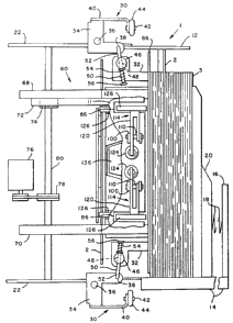
FIG. 1 represents a fragmented, top view of the envelope offset apparatus.
FIG. 2 represents a fragmented, side view of the FIG. 1 apparatus.
FIG. 3 represents a fragmented, cross-sectional top view of the apparatus.
Fig. 4 represents a fragmented, top view of the apparatus receiving a mail
piece.
Fig. 5. represents a side view of the apparatus receiving a mail piece.
Description Of The Preferred Embodiment
FIG. 1 illustrates a preferred embodiment showing a top perspective
view of an envelope offset apparatus 1 having a lower deck 10 which has
fixably mounted thereto, in vertical alignment, transversely spaced apart side
walls 12 and 14. The side walls serve principally as a lateral registration
abutment for each envelope 2 in the envelope stack 3. Lower deck 10 has a
guiding edge 15 for guiding an envelope 2 into the stacker 1. The lower deck
10 is fixably attached to a rear wall 16. A spring 18, having one end fixedly
attached to the rear wall 16, and the other end thereof fixedly attached to a
plate 20, supplies a biasing force which causes the plate 20 to remain in
contact with a forwardmost envelope in the envelope stack 3. The plate 20
-2-
serves principally as a longitudinal registration abutment for the envelope
stack 3 and secondarily as an obstructing mechanism which halts the forward
movement of the envelope stack 3.
Still referring to FIG. 1, pivotally mounted to a frame 22 of the
envelope stacker 1 is a normal force roller assembly 30 which comprises a
plate 32 and a bracket 34 having a pivot pin 36 and an aperture 38. The
bracket 34 further has an arm 40 with a shaft 42 extending therefrom. An idler
roller 44 is mounted to shaft 42.
A hub 46 rotatably mounted to plate 32 has a slot 48 through which
extends a generally L-shaped pin 50. A first end portion 52 of the L-shaped
pin 50 engages aperture 38 of bracket 34. A spring 54 is coiled around the L-
shaped pin 50 between a second end portion 56 of the pin 50 and the hub 46.
Referring now to FIGS. 1 and 2 concurrently, a vertically aligned
pusher 60 is fixably attached to plate 32. Pusher 60 is comprised of a base
62 supported by guides 64, a forward wall 66, and side walls 68 and 70 in
transversely spaced apart parallel alignment. Side wall 68 has mounted
thereon a rack gear 72. Pinion gear 74 is operatively connected to the rack
gear 72. A motor 76 is in drive communication with idler gear 78 which shares
a common shaft 80 with pinion gear 74 whereby rotation of the motor 76
thereby rotates the pinion gear 74.
Referring to FIGS. 1 and 3, the lower deck 10 and an upper deck 11
contain a plurality of slots 82, 84, 86, and 92. Fixably mounted to the
underside of the lower deck 10 and upper deck 11 are a plurality of
substantially U-shaped mounting blocks 100. Each mounting block 100 has a
plurality of apertures 108 for receiving a pivot pin 110. Input gates 112 are
connected to blocks 100 mounted to the underside of the lower deck 10.
Output gates 114, 116 are connected to blocks 100 mounted to the underside
of upper deck 11 and lower deck 10 respectively. The gates 112, 114, and
116 include a yoke-shaped end portion 120 pivotally connected to the
mounting block 100 by means of pin 110 such that the end portion 120 is
-3-
~~~2335
oriented parallel to the decks 10, 11. In order to retain the gates 112, 114,
and 116 in a home position, a spring 124 is secured to the deck 10 or 11. The
spring 124 has a free end which engages the end portion 120 of gates 112,
114, and 116 thereby biasing the gates 112, 114, and 116 toward the home
position.
Referring to FIGS. 2 and 3, each gate 112, 114, and 116 further has a
front portion 126 having an angled surface 130. The front portion 126 of each
gate 112, 114, and 116 extends generally perpendicular to the end portion
120 so that in the home position, the angled surface 130 extends through the
slots 82, 84, 86 in the deck 10, 11.
Still referring to FIG. 3, mounted to the underside of the lower deck 10
is a motor 132 having a shaft 134. A generally conical shaped elastomer
roller 136 is mounted onto the shaft 134 of the motor 132. The roller 136
extends above the lower deck 10 through slot 92 in deck 10. Roller 136 will
rotate in a clockwise or counterclockwise direction depending upon the
direction of rotation of motor shaft 134.
Referring now to FIGS. 2 and 3 concurrently, driving means for driving
an envelope 2 into the envelope stacker 1 comprises feed rollers 140, 142,
144, 146 rotated by a motor 148 coupled thereto by suitable means such as a
pulley drive 150, 152, or 154 entrained about rollers 140, 142, 144, 146.
Roller 156 is in drive communication with roller 140 by means of pulley 158.
PRACTICAL OPERATION
In the operation of our envelope stack offset apparatus 1, it is
desirable to provide indicating means to the operator collecting the envelopes
from the stacker to indicate separate groups of envelopes including, but not
limited to, those envelopes which are sealed or unsealed, different mailing
jobs, or changes in the zip code.
Turning now to FIG. 1, the operation of a specific embodiment of the
present invention is illustrated. In the home position depicted in FIG. 1, the
-4-
21~~~3~
pinion gear 74 is in rearmost engagement with the rack gear 72. Accordingly,
the pusher 60 is at a forwardmost position so that the forward wall 66
maintains contact with the last fed envelope of the stack of envelopes 3. In
the forwardmost position, the pusher 60 applies pressure to the last fed
envelope to further assist adhesion of the envelope flap to the envelope body
if the envelope was moistened before entering the stacker 1. In home
position, the idler roller 44 remains disengaged from feed roller 156.
When the stacker 1 receives a signal that an envelope is being
transported to the stacker 1, the motor 76 begins to rotate thereby moving the
pinion gear 74 forward within rack 72. This results in the pusher 60 traveling
in a rearward direction thereby causing the L-shaped pin 50 engaged with
bracket 34 to pivot the idler roller 44 into contact with feed roller 156. The
output gates 114 in conjunction with the spring biased plate 20 hold the stack
of envelopes 2 in an upright, vertical position to prevent the envelopes from
falling back and into the path of an incoming envelope in the absence of
pusher 60 (see FIG. 2).
Referring to FIGS. 2 and 4, upon receiving an appropriate signal, the
driving means drive an incoming envelope 2 into the stacker 1. A vertically
fed envelope 2 is guided between the nip of rollers 140 and 144 by the
guiding edge 15 of the lower deck 10. The envelope 2 is transported
vertically thereby engaging the angled surface 130 of the input gates 112.
The driving force of the envelope 2 against the input gates 112 will cause the
gates 112 to pivot in a direction perpendicular to the vertical path of travel
of
the envelope 2 thereby permitting the envelope 2 to engage the nip formed
by feed roller 156 and idler roller 44. After the bottom edge of the envelope
2
clears the input gates 112, the spring biased gates 112 will return to the
home position and the driving means will cease driving the envelope 2.
Referring to FIG. 5, the pinion gear 74 will rotate so as to move the
pusher 60 forward thereby causing the L-shaped pin 50 engaged with bracket
34 to pivot the idler roller 44 out of contact with feed roller 156. Pivoting
the
-5-
~1~~33~
idler roller 44 will cause the envelope 2 to drop vertically onto the top of
the
input gates 112. The motor 76 will momentarily discontinue forward motion of
the pinion gear 74 as the envelope 2 settles on the input gates 112.
Still referring to FIG. 5, after pausing for a predetermined time, the
motor 76 will resume driving the pinion gear 74 so that the pusher 60 moves
forward, displacing the vertically oriented envelope 2 in a substantially
horizontal direction. As the pusher 60 moves forward, the forward wall 66
drives the envelope 2 into contact with the surface of the elastomer roller
136. The forward motion of the pusher 60 causes the envelope 2 to bend
thereby providing additional normal force for driving the envelope 2 forward,
across the elastomer roller 136. As the envelope 2 is driven forward, the
roller 136 begins to rotate in a predetermined direction. The rotation of the
elastomer roller 136 in a predetermined direction will drive the envelope 2
laterally against a side registration edge 12 or 14 to either offset the
envelope
2 or register and align the envelope 2 with a common group of envelopes.
The pusher 60 continues to drive the envelope 2 forward and into contact
with the angled surface 130 of the output gates 114. As the pusher 60 moves
forward, the top edge and bottom edge of the envelope 2 causes the output
gates 114 to rotate in a direction perpendicular to the horizontal path of
travel
of the envelope 2.
The foregoing description of the preferred embodiment of the present
invention has been presented for purposes of illustration and description. It
is
not intended to be exhaustive or to limit the invention to the precise form
disclosed. Obviously, many modifications and variations will be apparent to
practitioners skilled in this art. The embodiment was chosen and described in
order to best explain the principles of the invention and its practical
application thereby enabling others skilled in the art to understand the
invention for various embodiments and with various modifications as are
suited to the particular use contemplated. It is intended that the scope of
the
invention be defined by the accompanying claims and their equivalents.
-6-