Note: Descriptions are shown in the official language in which they were submitted.
2~~3~~9
Medical svrinae
The invention relates to a medical syringe with a needle
attachment at the mouthpiece of the syringe cylinder, closed
until the syringe is to be used by a plug which may be in the
s form of a tip cap, the needle attachment being designed to
receive a cannula and secured to the mouthpiece of the
cylinder and sealed against the cylinder by a screw cap; the
screw cap is locked on to the mouthpiece of the cylinder by a
retaining ring pushed home on to it, while the retaining ring
io carries a firmly attached but detachable safety cap which
surrounds the needle attachment and the plug and consists
essentially of a hollow cylinder which is at least partially
closed at the end distant from the syringe cylinder by an end
plate.
15 A syringe of this type is known for example from
EP 0 397 951 and has proved very satisfactory in practice.
However, under certain circumstances it may happen that the
breaking point formed between the retaining ring and the
safety cap may already release or be damaged even when the
2o syringes are being assembled, if pressure from the safety cap
forces the retaining ring on to the needle attachment.
An object of the invention is to design a syringe of the
type referred to at the outset in such a way that it cannot
suffer damage of this kind.
= 2s According to one aspect of the present invention, there
is provided a medical syringe comprising a syringe cylinder
provided with an outlet, the syringe having a needle
attachment positioned at the outlet of the syringe cylinder
that is kept closed, until the syringe is used, by a plug, the
3o attachment being designed to receive a cannula and being
retained at the outlet and sealed against the syringe cylinder
by a screw cap, and the screw cap being locked on to the
outlet by a retaining ring pushed home around the outlet; the
retaining ring carries a firmly attached but detachable safety
35 cap, which surrounds the needle attachment and the plug and
2183389
comprises a hollow cylinder closed at least in part by an end
plate at a forward end not adjoining the syringe cylinder,
such that the safety cap and the retaining ring form a ring
slot between them and are connected through a number of
connecting pieces, while between each pair of connecting
pieces there is at least one spacer firmly attached to the
safety cap or the retaining ring and with its free end resting
against the retaining ring or the safety cap or facing the one
or the other with a small gap.
io The advantage of the invention is essentially the fact
that, when the retaining ring is pushed on to the needle
attachment the spacers transmit the force exerted through the
safety cap to the retaining ring without imposing loads on the
connecting pieces which could cause them to separate. But as
the spacers do not form a firm connection between the safety
cap and the retaining ring only the connecting pieces serve to
ensure retention of the safety cap before the syringe is used,
and they can be designed to ensure adequate retention of the
safety cap without making it necessary to use excessive force
2o to remove the safety cap. By separating the functions, that
is, by providing the connecting pieces as a detachable
connection between the safety cap and the retaining ring and,
on the other hand, having the force transmitted through the
spacers without loading the connecting pieces, it is possible
2s to optimize the characteristics of each without having the one
affect the other.
In case it proves necessary, especially because of
production considerations, to narrow the slot between the
spacers and the adjoining part, that is the retaining ring or
3o the safety cap, a preferred embodiment of the invention places
the connecting pieces obliquely along an imaginary helix.
This gives the connecting pieces adequate elasticity to ensure
that they will prevent damage if the spacers, when pressure is
applied, are temporarily displaced so that they rest against
35 the adjoining part.
-2-
2183389
For the purposes of the invention it is also advantageous
if the connecting pieces are distributed uniformly over the
circumference. In addition, it has been found advantageous to
taper the connecting pieces towards the retaining ring. In
s this connection it is advantageous to give the connecting
pieces an essentially pyramidal shape.
It is useful to design the spacers with a trapezoid
cross-section and to taper them towards the retaining ring.
An additional useful embodiment of the invention provides
io for the retaining ring to fit exactly around the cap and to be
retained along the line of the axis by a stop intervening
between the retaining ring and the screw cap. In a very
simplified embodiment the stop may take the form of a
projection on the inner surface of the retaining ring; this
i5 projection catches in a ring groove in the screw cap and
engages the screw cap at its rear end adjoining the syringe
cylinder.
In order to permit a check as to whether an assembled
syringe has a tip cap on its needle attachment the invention
2o provides for the safety cap to have an axially aligned hole on
its face the inside diameter of which is less than the
exterior diameter of the tip cap. Moreover, if, as is
advantageous, the inner side of the face of the safety cap
rests against the tip cap, this will ensure that the tip cap
2s cannot work itself loose from the needle attachment.
Finally, it is also possible to have the safety cap
tapered towards its forward end in the form of a truncated
cone.
An embodiment of the invention is described in detail in
3o the following with reference to the accompanying drawings, in
which:-
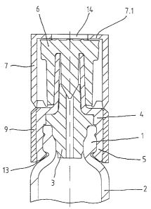
Fig. 1 is a longitudinal section of a syringe in
accordance with a preferred form of the invention;
Fig. 2 is side elevation of the embodiment of Fig. 1
3s showing the safety cap with the retaining ring; and
-3-
2183389
Fig. 3 is a section through the embodiment shown in
Fig. 2 taken along the line A-A.
The syringe of the preferred embodiment, which is only
partially illustrated in the drawings, is intended for medical
s purposes and consists of a cylinder 2 with a cylinder
mouthpiece 1 to which a needle attachment 3 is secured. The
rear end of this needle attachment 3 engages in the mouthpiece
1 with clean cut lamellas and, if used with pre-filled
syringes, is closed until it is to be used by a plug 6 which
io may take the form of a tip cap. The syringe cylinder,
moreover, has the usual refinement of finger support, not
shown in detail here, and at least one stopper activated by a
piston rod. If the syringe is designed to have two chambers,
the cylinder also has a bypass and an additional stopper which
i5 separates the pharmaceutical preparation, inserted before use
in freeze-dried form, from the solvent, which before the
syringe is used is fed through the bypass into the forward
chamber adjoining the cannula.
The needle attachment 3 is fitted with a cone to receive
2o a cannula, the needle attachment 3 being retained at the
cylinder mouthpiece 1 and sealed against the syringe
cylinder 2 by a screw cap 4. In the version illustrated, the
screw cap 4 also surrounds the needle attachment 3 in the
vicinity of the cone.
2s The screw cap 4 is locked on to the mouthpiece 1 by a
retaining ring 9 which is pushed home on to it. The retaining
ring 9 carries a firmly attached but detachable safety cap 7,
which surrounds the needle attachment 3 and the tip cap 6 and
consists essentially of a hollow cylinder.
ao The safety cap 7 and the retaining ring 9 form between
them a ring slot 8 (see Fig. 2) and are connected with each
other through a number of connecting pieces 10. Between each
pair of connecting pieces 10, a spacer 11 is placed, which is
firmly attached to the safety cap 7 and whose free end faces
35 the retaining ring 9 with a small gap.
-4-
2183389
The connecting pieces 10 form a rated breaking point
making it possible, for the purpose of attaching the cannula,
to easily break off the safety cap 7 which ensures that the
syringe will remain undamaged until it is to be used.
On the other hand, when the syringe is assembled, with
the retaining ring 9 being pushed on to the needle attachment
3 or the screw cap 4 so that the force is transmitted through
the safety cap 7, the spacers 11 ensure that the connecting
pieces 10 are not so loaded that any one or even all of them
io break off, as the force is transmitted essentially through the
spacers 11. The spacers 11 can therefore be designed to
permit an optimal transmission of force, while the connecting
pieces 10 can be optimized both to ensure that the safety cap
7 is adequately secured and to be detachable without
significant difficulty before the syringe is used.
As it is not as a rule possible, for reasons associated
with production technology, to provide a slot between the
spacer 11 and the retaining ring 9, the connecting pieces 10
are aligned obliquely along an imaginary helix. The
2o connecting pieces 10 are moreover uniformly distributed around
the circumference. As can be seen from Fig. 2, the connecting
pieces 10 are tapered towards the retaining ring 9 and are
essentially pyramidal in shape.
The spacers 11, on the other hand, have a trapezoidal
cross-section and they too are tapered towards the retaining
ring 9.
The retaining ring 9 fits exactly around the screw cap 4
and the alignment of its axis is maintained by a stop 13
engaging with the screw cap 4. This stop 13 is formed by a
3o projection on the interior surface of the retaining ring 9
which engages with the screw cap 4 at its rear end adjoining
the syringe cylinder 2.
In order to make it possible to check the assembled
syringe to see whether the plug 6, that is, the tip cap, is
placed on the needle attachment, the safety cap 7 has an
-5-
2183389
axially aligned hole 14 on its forward side, whose inner
diameter is less than the exterior diameter of the tip cap 6,
so that the latter cannot be separated from the needle
attachment 3 until the safety cap 7 is detached. In addition,
s to prevent the tip cap 6 from working loose it is advantageous
to place the safety cap with the inner side of its forward
side 7.1 resting against the tip cap. For this purpose, it is
also useful to have the safety cap 7 tapered towards its
forward end in the form of a truncated cone, in order to
io ensure that the tip cap 6 is centred.
-6-