Note: Descriptions are shown in the official language in which they were submitted.
i
MOTOR VEHICLE HEADLAMP
1. Field of the invention.
The present invention relates to electric lamps, and in
particular vehicle headlamps. Still more particular, the
invention relates to headlamps having compound optical
elements.
2. Description of the Background Art.
Headlamps are designed to accomplish several goals at
once. They must illuminate both near and far regions in
front of a driver, without detrimentally effecting the
vision of other drivers. This is accomplished at a minimum
by forming a beam pattern that complies with automotive
lighting requirements. At the same time, styling,
aerodynamics, size, weight and cost are factors that must
also be dealt with. Beam patterns are then constructed with
variety of considerations at once. The beam pattern
includes a region of high intensity called a hot spot that
is normally built by effectively overlaying numerous
reflected images from the light source. Reflectors with
relatively long focal lengths, have small source images that
can be grouped in an angularly narrow region to form the hot
spot. At the same time, a headlamp high beam for example,
must spread some light right, left, above and below the hot
spot to broaden the driver's view. Reflectors with short
focal lengths, have large source images that can be spread
over a broad area. The conflict between short and long
- 1 -
~2~ ~i ~u
focal lengths is apparent. Further, headlamps should
efficiently use the available light, so the source may be
designed for longevity, or energy efficiency. Lamp
efficiency is achieved by intercepting and reflecting a
S greater portion of the light from around the light source.
Capturing more of the light by reflecting it from more of
the surrounding spherical area, means the light is
necessarily captured at a greater variety of angles. It
also means relatively less spherical area is available to
direct the light through to the field to be illumiated. All
these factors complicate the design.
In a typical prior art sealed beam headlamp with a
parabolic reflector and refractive cover lens, the light
source is disposed near the focus of the reflector, so rays
emitted from the light source are reflected forward,
parallel to the axis of the paraboloid. The parallel beams
are then refracted by the prisms and lenses of the cover
lens to form a predetermined beam pattern. The design
relies on a relatively large focal length to form the
necessary hot spot in the beam, while beam spread is
achieved by the lens optics. For efficiency, a relatively
large reflector area is used to gain the necessary solid
angle. The design is not particularly adaptable to fit with
styling variations in the surrounding vehicle body. The
reduction of the overall height for styling, and inclination
of the lens surface for aerodynamics cause a significant
reduction in the overall headlamp efficiency. The reduced
height can, to a degree, be offset by increased width, but
only with diminishing returns. Usually the total frontal
area is increased in this trade off, and the large frontal
- 2 -
~2U ~i ~U
area is of itself a styling and aerodynamic detriment. It
is then not practical to make an efficient, parabolic
reflector type headlamp with a small frontal area.
Currently, there is a trend to move the beam forming
optics from the cover lens to the reflector. The headlamp
then has a reflector with a complex surface, such as a
compound-curvature or multifaceted surface, and a clear
cover lens. Since, the clear cover lens has little or no
optical effect on the beam pattern, it can be configured to
carry all the styling and aerodynamic constraints. The
problems with focal length tradeoffs and the degree of
enclosure are approximately the same in both the parabolic
reflector/refractive lens, and the complex/clear lens type
headlamps. The later then still require a relatively large
frontal area.
To increase efficient use of the light from the filament
and at the same time allow for a small frontal area, one
method is to use a projector type lamp. FIG. 1 shows a
schematic side view of a projector type headlamp. These
headlamps use an elliptical reflector to intercept a large
portion of the light from around the light source. The
large amount of collected light is then directed to a
converging lens that collimates and spreads the available
light. The light source is placed to coincide with one
focal point of the elliptical reflector to thereby project
light through a narrow region approximately at a second
focal point. A mask is usually placed in the vicinity of
the second focal point to block light and thereby helps
define some of the beam pattern edges (cut off). The mask
- 3 -
CA 02201205 2004-03-22
77332-143
removes available light from being usefully projected. The
light is then passed through a small reflector opening to
concentrate the flux on the converging lens. The image of
the filament produced by the elliptical reflector is then
located at the second focal point, coinciding with the first
focal point of the positive converging lens (between the
reflector and lens). The rays from the filament image are
then refracted by the converging lens to form the beam
pattern. An optically clear cover lens may be placed in
front of the converging lens for styling and aerodynamics.
A typical projector headlamp design requires a
relatively long axial dimension to span the distance between
the two focal points and include the reflector behind the
one focal point and the lens in front of the other. The
headlamp then extends deep under the hood and competes for
valuable internal space. There is then a need for a
headlamp forming a beam pattern including hot spot, and
spread regions wherein the headlamp has a relatively small
frontal area, and a relatively short axial extension.
Summary Of The Invention
According to one aspect the invention provides a
vehicle headlamp comprising: a light source; a divergent
lens having a first focal point, and a lens axis passing
through the light source and the first focal point of the
lens; and a reflector having a reflective surface facing in
a forward direction to the light source and the lens to
reflect light from the light source towards the lens, the
reflective surface having, at least a first region
comprising a portion of a type 1 surface, being an ellipsoid
of revolution with a respective first and second focal
point, the first reflector region being oriented with the
4
CA 02201205 2004-03-22
77332-143
first respective focal point located at the light source,
and the second respective focal point located at the first
focal point of the lens; and at least a second region
comprising a portion of a type 2 surface having an
elliptical vertical axial cross section with associated
first focal point and second focal point; and having a
horizontal axial cross section with associated first focal
point and second focal point, the second reflector region
being oriented to locate the first focal point of the
vertical cross section, and the first focal point of the
horizontal cross section at the light source, and the second
focal point of the vertical cross section at the first focal
point of the lens, and the second focal point of the
horizontal cross section axially offset from the first focal
point of the lens.
According to another aspect the invention provides
a vehicle lamp providing a hot spot and beam spread portions
comprising: a light source sufficient to meet automotive
headlight lumen requirements; a divergent, concentric
Fresnel lens having a first focal point, an axis of rotation
passing through the light source and the first focal point
of the lens, the lens having a dimension orthogonal and
through the lens axis, and a reflector with a reflective
surface, the reflector being axially offset from the lens,
and wherein the lens has an active portion having a
dimension that is less than a dimension measured across a
forward most, active portion of the reflector, with both
dimensions being orthogonal through the lens axis, and
parallel to each other, the reflective surface further
having at least a first region, a second region and a third
region each comprising a portion of a type 1 surface, the
type 1 surface being an ellipsoid of revolution with a
respective first and second focal point, the first region,
5
CA 02201205 2004-03-22
77332-143
second region and third region being oriented so that each
respective first focal point is located at the light source,
and each respective second focal point is located at the
first focal point of the lens; and at least a fourth region
and a fifth region each comprising a portion of a type 2
surface, each type 2 surface having an elliptical vertical
axial cross section with respectively a first focal point
and a second focal point; and having a horizontal axial
cross section with respectively a first focal point and a
second focal point, the fourth region and the fifth region
being oriented to locate respectively the first focal points
of the vertical cross sections, and the first focal points
of the horizontal cross sections at the light source, and
the second focal points of the vertical cross sections at
the first focal point of the lens, and the second focal
points of the horizontal cross sections displaced from the
first focal point of the lens; whereby light from the light
source reflected from the first region, from the second
region and third region enters the lens to be refracted and
then exits the lens along substantially axially parallel
lines, and whereby light from the light source reflected
from the fourth region and the fifth region enters the lens
to be refracted and then exits the lens in substantially
horizontally parallel planes.
Brief Description Of The Drawings
FIG. 1 shows a schematic drawing of a prior art
projector type headlamp with an elliptical reflector, shadow
mask, converging lens, and clear cover lens;
FIG. 2 shows a schematic cross section of a
preferred embodiment of a headlamp with a diverging lens and
a clear cover lens;
5a
CA 02201205 2004-03-22
77332-143
FIG. 3 shows a side cross sectional view of the
divergent lens;
FIG. 4 shows a front view of the divergent lens of
FIG. 3;
FIG. 5 shows a side cross sectional view of a
preferred divergent Fresnel lens;
FIG. 6 shows a front view of the divergent lens of
FIG. 5;
FIG. 7 shows a portion of a type 1 surface;
FIG. 8 shows an axial cross section of a schematic
optical system;
5b
FIG. 9 shows a portion of a type two surface.
FIG.s 10, 11, 12, and 13, show axial cross sections of
schematic optical systems;
FIG. 14 shows a front view of a reflector;
FIG. 15 shows a cross section, top view, of a preferred
embodiment of a headlamp light source, reflector
and a diverging Fresnel lens; and
FIG. 16 shows a sample angular luminous intensity
distribution from the present invention
(isocandella beam pattern).
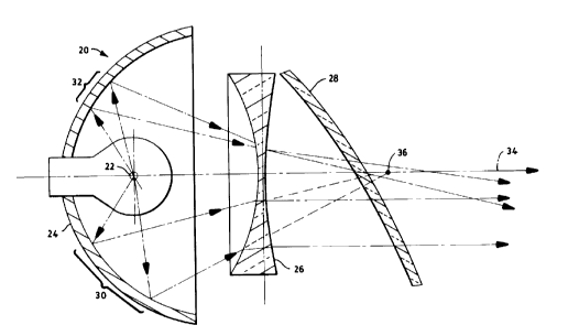
FIG. 2 shows a schematic cross section of a preferred
embodiment of a vehicle headlamp 20. The headlamp 20 may be
formed with a light source 22, a reflector 24, and a
diverging lens 26. Additionally a cover lens 28, housing,
sealing, aiming and adjustment, attachment and support
mechanisms (not shown) may be applied according to design
choice as may be necessary and appropriate, as is generally
understood in the art of lamp making.
The light source 22 may be any small optical light
source, for example one typical of those commonly used in
automotive designs. Tungsten filaments are commonly used as
headlamp light sources, but electroded and electrodeless
high intensity discharge sources may also be used. The
preferred light source 22 provides the necessary total
number of lumens from a small volume to conveniently form a
beam pattern. Useful light sources would include the
- 6 -
~~UI~v~
typical 9004, 9005/6, 9007 and D1 type tungsten halogen lamp
capsules. It is understood that a real light source is not
a point source, so there is necessarily small spread of
light around each ideal ray depending on the source size.
FIG. 3 shows a side cross sectional view of the divergent
lens 26, and FIG. 4 shows a front view of the same divergent
lens 26 of FIG. 3. The preferred lens material is
transparent, inexpensive, and has good optical and thermal
properties, such as glass, acrylic, or one of a variety of
high temperature plastics. Plastic may be accurately and
inexpensively formed with relatively high quality optics.
While it is possible to form a diverging lens 26 from glass,
the preferred lens material is a clear polycarbonate
plastic. For manufacturing simplicity, the preferred
diverging lens 26 is rotationally symmetric about a central
axis 34. Asymmetrical lenses may also be used.
The diverging lens 26, (FIG. 2) has a first focal point
36 as understood and defined in the art of lens making. The
first focal point 36, for a diverging lens 26 is imaginary,
and for a rotationally symmetric lens is located along the
lens axis 34, and on a side of the lens 26 away from the
light source 22, meaning here in the region on the forward
side of the lens 26.
As is known in the lens making art, there are numerous
forms of diverging lens that may be appropriate for use in a
headlamp. The lens may be a solid plate concave on one or
both sides. The lens may have more of an overall bowl
shape. It may have a smooth surface, or a stepped surface.
FIG. 5 shows a side cross sectional view of a preferred
_ 7 _
~2UI~~~
divergent Fresnel lens 38. FIG. 6 shows a front view of the
divergent Fresnel lens 38 of FIG. 5. The preferred Fresnel
lens 38 includes a smooth, concave surface 40 on a side
facing the light source 22, and the reflector 24. On the
side 41 facing away from light source 22, and the reflector
24, the side facing in the forward direction, the lens 38
includes several stepped, refractive regions, rotationally
symmetric about a central axis 42 (concentric, divergent
Fresnel lens).
The reflector 24, (FIG. 2) may be made of an aluminized,
molded plastic as is commonly done. The reflective surface
is aligned to face the light source 22 and the lens 26 to
reflect light from the light source 22 through the lens 26
in a forward direction. The reflector 24 includes at least
a first region 30, and a second region 32. Additional
regions may also be included.
The reflector 24 is formed with at least a first region
30 taken from an ellipsoid of revolution (type 1 surface).
FIG. 7 shows a portion of an ellipsoid of revolution 46.
The vertical axial cross section 48 (XZ plane) is elliptical
with a first focal point 50. A second focal point 52 is
located along the X axis 54, forward of the first focal
point 50. The horizontal axial cross section 56 (XY plane)
is also elliptical with a the same first focal point 50, and
the same second focal point 52. Axial cross sections taken
between the vertical and horizontal are similar. Light rays
emitted at the first focal point 50 are then reflected
towards the second focal point 52.
- s -
'7
If a light source is positioned at the first focal point
50, and a diverging lens is positioned so that the second
focal point 52 of the reflector is the same as the first
focal point of the lens, then light emitted from the light
source is substantially collimated. FIG. 8 shows a
schematic diagram of an optical system arranged with these
conditions. For an ellipsoid of revolution, the vertical
and horizontal cross section are similar, so only one is
discussed. Ray 58 emitted at the first focal point 60 is
reflected on one side of the reflector 62 towards the second
focal point 64 of the reflector 62. Ray 58 is refracted by
the lens 66, similar to the way an incoming axial ray 68
(presented as a comparison standard) is refracted. Ray 58
is therefore axially collimated, bringing ray 58 into
parallel with the axis 70. Collimated rays, such as ray 58,
can then be use to build the hot spot. An elliptical
reflector section taken from an ellipsoid of revolution with
a second focal point at the first focal point of a diverging
lens, then yields a collimated beam that can be used for
building the hot spot of a headlamp beam.
The reflector 24 (FIG. 2) further includes at least one
region 32 taken from a second surface type. FIG. 9 shows a
portion of a type 2 surface 72. The vertical axial cross
section 74 (XZ plane) is elliptical with a first focal point
76. A second focal point 78 is located along the X axis,
forward of the first focal point 76. The horizontal axial
cross section 80 (XY plane) also has a first focal point
located at the same first focal point 76. The horizontal
axial cross section 80 has a second focal point 82 located
along the X axis, but not at the same position as the second
- 9 -
?2~i~~5
focal point 78 associated with the vertical axial cross
section 74. Second focal point 82 is then axially off set
from the second focal point 78. The horizontal axial cross
section 80 may be elliptical, parabolic, or hyperbolic.
Axial cross sections taken between the vertical and
horizontal may have forms with second focal points located
between points 78 and 82.
By ,~~sitioning a light source at the first focal point
76, an,ci positioning a diverging lens so that the second
focal point 78 of the reflector is the same as the first
focal point of the lens, then light emitted from the light
source is substantially directed in planes parallel to the
horizontal. This is similar to the ellipsoid of revolution
surface. However, rays in horizontal planes are diverged to
the sides, and are generally not parallel to the vertical
axial plane 74.
The preferred embodiment of the type two surface is
defined by the following the equation:
aX' + bXY2 + cXZ2 + dXz + eYz + f Z2 + gX = 0
where
X = the lamp axis dimension
Y = the horizontal dimension
Z = the vertical dimension
a = be = (1 + KZ) (1 + Ky)
b = (1 + KZ)
c = (1 + Ky)
d = bf + ce = (-2) (Ry(1 + KZ) + RZ(1 + Ky) )
a = (-2) (RZ)
- 10 -
220i~05
f = (-2) (Ry)
g = ef = 4 (RZ) (Ry) .
Ry and RZ are positive constants representing radii of
curvature at the axial intersection of the surface (vertex)
in the horizontal and vertical axial planes respectively.
Ky and KZ are constants for the horizontal and vertical
sectional curves, respectively, with KZ greater than -1.
By selecting a value of KZ greater than -1, the vertical
axial cross section is then elliptical. The horizontal
cross section, depending on the value of Ky can be
elliptical, parabolic or hyperbolic. Since a reel light
source has real dimension, Ry and RZ need not be exactly
equal but may, for example, differ by approximately the size
of the light source.
FIG.s 10, 11, 12 and 13 show schematic diagrams of
optical systems regarding the horizontal axial plane of FIG.
9. In FIG. 10, ray 84 emitted at the first focal point 86
of the horizontal axial cross section is reflected on one
side of the reflector 88 towards the second focal point 90
of the reflector 88 that is positioned between a light
source at point 86 and the first focal point 92 of the lens
94. Ray 84 is refracted by the lens 94, less than an amount
sufficient to bring the ray 84 parallel to the axis 96.
Light from the reflector 88 is then directed across the axis
96, and not parallel the axis 96.
In FIG. 11, ray 98 emitted at the first focal point 100
of the reflector 102 is reflected on one side of the
reflector 102 towards the second focal point 104 of the
- 11 -
~2U ~ X05
reflector 102 that is positioned beyond the first focal
point 106 of. the lens 108. Ray 98 is refracted by the lens
108, more than an amount sufficient to bring the ray 98
parallel to the axis 110. Light from the reflector is then
directed away from the axis 110, and not parallel the axis
110.
In FIG. 12, ray 112 emitted at the first focal point 114
of the reflector 116 is reflected on one side of the
reflector 116 with a parabolic horizontal cross section
towards a second focal point (not shown) located at
infinity. Ray 112 is then diverged by the lens 118. Light
from the reflector is then directed away from the axis 120,
and not parallel the axis 120.
In FIG. 13, ray 122 emitted at the first focal point 124
of the reflector 126 is reflected on one side of the
reflector 126 with a hyperbolic horizontal cross section
away from a second focal point 128 (imaginary) located
behind the reflector 126. Ray 122 is then diverged by the
lens 130. Light from the reflector is then directed away
from the axis 132, and not parallel the axis 132.
In any case, (FIG. 10, 11, 12, or 13 regarding FIG. 9)
the rays 84, 98, 112 and 122 in the horizontal axial plane
86, are not collimated, and spread away from the lens axis.
An ellipsoidal, parabolic or hyperbolic reflector section
with a horizontal axial cross section whose second focal
point is not at the first focal point of the lens, yields a
spreading beam that can be used for building portions of the
beam away from the hot spot. Portions from the type 2
- 12 -
'2~~~0~
surface are then useful for forming blend and spread
portions of the beam pattern.
Vehicle beam patterns are irregularly shaped with some
light needed low on the driver's side, little or no light
high on the driver's side, good light in the center low,
maximum light in the center just below straight on, and so
forth. No single, simple surface provides a correct beam
pattern. It is then the art of lamp building to construct
beam patterns piecemeal from useful sections of reflectors.
Headlamp design here is then carried out by forming one or
more type 1 surfaces, and one or more type 2 surfaces, and
then selecting sections of the each type and piecing them
together to built a satisfactory beam pattern.
FIG. 14 shows a front view of a preferred embodiment of a
reflector 134. The reflector 134 shows a region 136
extending from the horizontal midline at the reflector
center, symmetrically, upwards to the top edge of the
reflector 134. A similar region 138 extends from the
horizontal midline to two points along the lower edge of the
reflector 134. Formed respectively to the right and to the
left of the two type 2 regions 136 and 138, are two type 1
regions 140 and 142. A third type 1 region 144 is formed in
a segment along the bottom edge of the reflector 134.
Regions 140, 142, and 144 are type 1 regions, portions of an
ellipsoid of revolution. Regions 136 and 138 are type 2
regions.
In the preferred embodiment, the reflector and lens are
fixed relative to each other. The fixed relation is easily
accomplished by extending a rigid connection between the
- 13 -
~'2~ ~ ~Q5
two, for example by extending a flange from the reflector,
and a flange from the lens, and then rigidly linking the two
flanges, for example by studs and bolts.
FIG. 15 shows a top cross sectional view of a preferred
embodiment of a headlamp subassembly 146 with a light
source, a reflector with type 1 and type 2 regions and a
diverging lens. This is the same reflector 134 as seen in
FIG. 14. A 9005 type head lamp capsule 148 with an axially
aligned filament light source 150 is coupled through the
rear of a reflector 134. The reflector 134 has two type two
regions 136 (not shown) and 138 and three type 1 regions,
140, 142, and 142 within its reflective area. A reflector
flange 152 extends transverse to the lens axis. Attached to
the reflector flange 152 are of forward projecting, screwed
in place studs 154. The forward most ends of the studs 154
are in turn attached to a lens flange 156. The lens flange
156 also extends transverse to lens axis. The lens flange
156 supports a lens 158 that includes a smooth, concave
inside surfaced 160 facing the filament light source 150.
The lens 158, on the forward facing side, includes a stepped
surface 162 with six, concentric stepped refractive rings.
The lens 158 is then a diverging, Fresnel type lens. The
lens is located forward of the forward most portion of the
reflector 134. The active portion of the lens 158 has a
dimension 164 that is less than a dimension 166 measured
across the forward most, active portion of the reflector
134, with both dimensions being orthogonal through the lens
axis, and parallel to each other. The lens 158 is then
smaller than the reflector 134 opening, while receiving all
of the light reflected by the reflector 134.
- 14 -
X20 l ~~5
The lamp may be enclosed with a cover lens that may be
any clear, and lens free (optically neutral), or nearly lens
free cover. The preferred cover is made from a clear
polycarbonate or similar material coated with abrasion
resistant, and other protective coating as are generally
known in the art. The cover lens may be conveniently formed
to meet chosen styling and aerodynamic requirements of the
vehicle under design.
In operation, the light source is positioned to be at or
near the locus of first focal points of the reflector
regions, so light emitted from the light source strikes the
reflector in the type 1 regions) and the type 2 region(s).
Light is then directed from the type 1 regions) towards the
first focal point of the lens to be axially collimated.
Light reflecting from the type 2 regions) is directed
horizontally, but either crosses or spreads away from the
vertical axial plane. Light from the reflector type 2
region may then used to form the blend and spread regions of
the beam.
FIG. 16 shows a sample angular luminous intensity
distribution from the present invention (isocandella beam
pattern). The beam pattern was the result of a headlamp
with the structure shown in FIG.s 14 and 15.
It is also common practice to set up an initial lens
prescription using ideal geometric forms, such as the
segments of the base reflector used to form the complete
reflector. In practice, seams are formed along the
interfaces of the various segments. The over lap in the
final beam pattern from light reflected from adjacent
- 15 -
~2(J j ~~.fi
reflector regions may be sufficient to mask any seam lines.
In other instances, these seams may cause light or dark
streaks in the illuminated field. It is known in practice
to submit such ideal prescriptions to computer processing
that smoothes out the interface regions, yielding a smooth
surface, for example one with continuous first and second
derivatives. In this processing the ideal geometric forms
are no longer ideal, but only approximations of the ideal.
It is also common, for an optical designer to sculpt,
according to his preferences, within the limits permitted by
a standard, the elements of an optical system to enhance or
reduce the amount of light delivered to sections of the
illuminated field. Such tweaking of the reflector or lens
elements also makes the final optical surfaces difficult to
prescribe, in simple terms. It is also understood that
exact geometric forms may be approximated by closely similar
curves that are not exactly elliptical, parabolic or
hyperbolic, the functional result is nonetheless
substantially the same. The terms elliptical, parabolic and
hyperbolic are then intended here to encompass such
approximating forms.
In a working example some of the dimensions were
approximately as follows: The reflector was made from a
bulk molding plastic compound (BMC), and had a 113.3
millimeter (4.46 inch) inside diameter and a 46.5 millimeter
(1.83 inch) axially dimension. The focal length of a type 1
region of the reflector was 25.0 millimeters (0.98 inches).
The focal length of a type 2 region of the reflector varied
from 23.2 millimeters (0.91 inches) to about 28.5
millimeters (1.12 inches). The light source was a 65 watt
- 16 -
~~2U ~ ~~~
halogen bulb (9005 vehicle bulb) with a tungsten filament
positioned parallel to the optical axis of the lens. The
Fresnel lens had the shape of a circular dome molded from
optical grade polycarbonate with a circular disk with two
S sideways extending flanges used for mounting. The lens had
an outer diameter of 90 millimeters (3.54 inches)'. The
inside surface facing the reflector was a smooth, concave
spherical surface having a radius of 100 millimeters (3.94
inches). The axial depth of the lens was 13.4 millimeters
(0.53 inches). The outer lens surface (forward side, facing
away from the reflector) had six concentric refractive
diverging zones formed as torodial surfaces. They were
arranged concentrically around the center of the lens. The
lens thickness varied from 2.0 millimeters (0.08 inches) to
5.4 millimeters (0.21 inches). The geometrical definition
of the refractive zones was as follows:
zone RLZ (mm) hmin (mm) hmaX (mm)
#
1 170 0.0 18.5
2 10,000 18.5 23.5
3 10,000 23.5 28.5
4 10,000 28.5 33.5
5 241.9 33.5 38.5
6 146.7 38.5 45.0
The zones refer to the refractive diverging rings and are
numbered from the inside ring 1 to the outside ring 6. Rr,2
is the radius of curvature of respective torodial surface in
the median section plane measured in millimeters. The h",in
is the minimum radial dimension measured in the median plane
- 17 -
L2U I ~~S
in millimeters. The hm~ is the maximum radial dimension of
the zone measured in the median plane millimeters.
The lens was aligned to be normal to the reflector axis
with the lens center positioned 61.4 millimeters in front of
the light source. The axial length of the lamp from the
apex of the reflector to the outermost surface of the lens
was 88.2 millimeters (3.47 inches), while the weight of the
unit was 0.26 kilograms. The diverging lens had a negative
focal length of approximately 110 millimeters, so that the
axial dimension of the lamp was smaller than a projector
type headlamp using a converging lens with a positive focal
length of 110 millimeters. The difference was approximately
twice the focal length, or 220 millimeters (8.7 inches).
The reflector had five regions defined by the equation
disclosed above and the following respective coefficient
values:
region RZ mm Ry mm KZ Ky
1 44.15 44.15 -0.587 -0.587
2 44.15 44.15 -0.587 -0.587
3 44.15 44.15 -0.587 -0.587
4 49.67 47.00 -0.550 -1.050
5 42.27 42.00 -0.600 -0.450
Each region elliptical vertical
had axial cross sections.
Regions 2, 3, d 5 had ellipticalhorizontalaxial cross
1, an
sections. Region had a hyperbolic horizontalaxial cross
4
section.
The intensity of the hot spot was above 44,500 candelas
and the spread of the light was from -19 to + 19 degrees
horizontally and from -9 to +12 degrees vertically. The
- 18 -
?2~ ~ ~y5
total luminous flux in the output beam was measured to be
770.5 lumens, which corresponds to an efficiency of 45.3
percent for the lamp. assembly. FIG. 16 shows a sample
angular luminous intensity distribution (isocandella beam
pattern) for the lamp assembly using the present invention.
The beam pattern as shown in FIG. 16 meets all of the
existing required beam pattern limitations (FMVSS 108). The
disclosed dimensions, configurations and embodiments are as
examples only, and other suitable configurations and
relations may be used to implement the invention.
While there have been shown and described what are at
present considered to be the preferred headlamp embodiments
of the invention, it will be apparent to those skilled in
the art that various changes and modifications can be made
herein without departing from the scope of the invention
defined by the appended claims. In particular, the design
may be adapted to other projector type lamp applications.
- 19 -