Note: Descriptions are shown in the official language in which they were submitted.
CA 02202288 1997-04-09
1
LENS DEVICE AND AN OPTICAL PICKUP APPARATUS
USING TIEIE LENS DEVICE
Technical Field
The present invention relates to a lens device and method of making same,
a method of obtaining a stable focus servo signal, an optical pickup adopting
the
same, a method of discriminating discs having different thicknesses and a
method
of reproducing/recording information fr~m/onto the 'discs.
Background Art
An optical pickup records and reproduces information such as video or
audio data onto/from recording media, e.g., discs (or disks). A disc has a
structure
that an information-recorded surface is formed on a substrate. For example,
the
substrate can be made of plastic or glass. In order to read or write
information
from a high-density disc, the diameter of the optical spot must be very small.
To
this end, the numerical aperture of .an objective lens is generally made large
and a
light source having a shorter wavelength is used. However, in case of using
the
shorter wavelength light source, a tilt allowance of the disc with respect to
optical
axis is reduced. The thus-reduced disc tilt allowance can be increased by
reducing
the thickness of the disc.
Assuming that the tilt angle of the disc is B, the magnitude of a coma
aberration coefficient RT31 can be obtained from:
- d n 2(n 2-1)sin8 cos9 NA 3
s
(n 2 - sin29) Z
where d and n represent the thickness and refractive index of the disc,
respectively.
As understood from the above relationship, the coma aberration coefficient is
proportional to the cube of the numerical aperture (NA). Therefore,
considering
that the NA of the objective lens required for a conventional compact disc
(CD) is
0.45 and that for a conventional digital video disc or digital versatile-disc
(DVD)
is 0.6 (to accommodate the higher information density), the DVD has a coma
CA 02202288 1997-04-09
2
aberration coefficient of about 2.34 times that of the CD having the same
thickness
for a given tilt angle. Thus, the maximum tilt allowance of the DVD is reduced
to about half that of the conventional CD. In order to conform the maximum
tilt
allowance of the DVD to that of tine CD, the thickness d of the DVD could be
5 reduced.
However, such a thickness-reduced disc adopting a shorter wavelength (high
density) light source, e.g., a DVD, cannot be used in a recording/reproducing
apparatus such as a disc drive for the conventional CDs adopting a longer
wavelength light source because a disc having an non-standard thickness is
10 influenced by a spherical aberration to a degree corresponding to the
difference in
disc thickness from that of a normall disc. If the spherical aberration is
extremely
increased, the spot formed on the disc cannot have the light intensity needed
for
recording information, which prevents the information from being recorded
precisely. Also, during reproduction of the information, the signal-to-noise
(S/N)
15 ratio is too low to reproduce the recorded information exactly.
Therefore, an optical piclcup adopting a light source having a short
wavelength, e.g., 650nm, which is compatible for discs having different
thicknesses, such as a CD or a DVD, is necessary.
For this purpose, research into apparatuses capable of recording/reproducing
20 information on either of two disc types having different thicknesses with a
single
optical pickup device and adopting a shorter wavelength light source is under
progress. Lens devices adopting a combination of a hologram lens and a
refractive
lens have been proposed in, for example, Japanese Patent Laid-Open Publication
No. Hei 7-98431.
25 FIGS. 1 and 2 show the focusing of zero-order and first-order-diffracted
light onto discs 3a and 3b having different thicknesses, respectively. In each
figure, a hologram lens 1, provided with a pattern 11, and a refractive
objective
lens 2 are provided along the light path in front of discs 3a and 3b. The
pattern
11 diffracts a light beam 4 from a light source (not shown) passing through
30 hologram lens 1, to thereby separate the passing light into first-order-
diffracted
light 41 and zero-order light 40 each of which is focused to a different point
on the
optical axis with a different intensity by the objective lens 2. The two
different
CA 02202288 1997-04-09
3
focal points are the appropriate focus points on the thicker disc 3b and the
thinner
disc 3a, respectively and thus enable data read/write operations with respect
to
discs having different thicknesses.
However, in using such a lens system, the separation of the light into two
beams (i.e., the zero order and first order light) by the hologram lens 1
lowers the
utilizing efficiency of the actually used (reflected and partially twice
diffracted, 1st
order) light to about 15 % . Also, during the read operation, since the
information
is riding on one of the beams while the other beam is carrying no information.
the
beam that is carrying no information is likely to be detected as noise.
Moreover,
the fabrication of such a hologram lLens requires a high-precision process
used in
etching ~, fine hologram pattern, which increases manufacturing costs.
FIG. 3 is a schematic diagram of another conventional optical pickup device
as disclosed in U.S. Patent No. 5,281,797. This optical pick-up device
includes
a variable diaphragm la for varying the aperture diameter, so that data can be
recorded onto a longer wavelength disc as well as a shorter wavelength disc,
but
with the discs having the same thickness, and information can be reproduced
therefrom. The variable diaphragm la is installed between the objective lens 2
and
a collimating lens 5. The variable diaphragm la controls a beam 4 emitted from
a light source 9 and transmitted through a beam splitter 6, by appropriately
adjusting the area of the beam passing region, i.e., the numerical aperture
(NA).
The diametral aperture of the variable diaphragm la is adjusted in accordance
with
the spot size required by the disc to be used and always passes the annular
beam
' 4a of the central region but selectively passes or blocks the beam 4b of the
peripheral region. In FIG. 3, a reference numeral 7 denotes a focusing lens
and
a reference numeral 8 denotes a photodetector.
In the optical device having the above configuration, if the variable
diaphragm is formed by a mechanical diaphragm, its structural resonance
characteristics change depending on the effective aperture of the diaphragm.
The
installation of the diaphragm onto an actuator for driving the objective lens
becomes
difficult in practice. To solve this problem, liquid crystals may be used for
forming the diaphragm. This, however, greatly impedes the miniaturization of
the
system, deteriorates heat-resistance and endurance and increases manufacturing
CA 02202288 1997-04-09
1
4
costs.
Another approach is disclosed. in U.S. Patent 5,496,995. As disclosed, a
phase plate in placed in a light path of an objective lens. The phase plate
creates
first and second light sources of different phases such that the amplitudes of
the
lateral sides of a main lobe of an image of the first light source are
cancelled by
the amplitude of the main lobe of an image of the second light source by
superimposition. In one embodiment, annular opaque rings separate grooves of
different depths, the grooves providing the phase difference. A problem
inherent
to this approach is the need to carefully control the groove depth and light
amplitudes, for example, to create the proper phase change and lobe
cancellation.
Alternatively, a separate objf:ctive lens for each disc may be provided so
that a specific objective lens is used for a specific disc. In this case,
however,
since a driving apparatus is needed for changing lenses, the configuration
becomes
complex and the manufacturing cost increases accordingly.
Disclosure of the Invention
It is an object of the present invention to provide a lens device which is
inexpensive and easily fabricated, a method of obtaining a stable focus servo
signal,
an optical pickup adopting the sanne, a method of discriminating discs having
different thicknesses and a method for reproducing/recording information
from/onto
the discs.
It is another object of the present invention to provide an objective lens
whose light utilizing efficiency is enhanced and which can form aberration
reduced
spots, a method of obtaining a stable focus servo signal, an optical pickup
adopting
the same and a method for reproducing/recording information from/onto the
discs.
To accomplish the above objects, there is provided lens device including a
lens focussing light into a focal zone and having a predetermined effective
diameter; and light controlling means provided in a light path of the lens for
preventing light in an intermediate axial region of the light path from
reaching the
focal zone, the intermediate axial region being located between a near axial
region
which includes a center of the light path and a far axial region located
radially
outward from the intermediate region, the light controlling means permitting
light
CA 02202288 1997-04-09
in the near and far regions of the light path to reach the focal zone.
Also, according to another aspect of the present invention, there is provided
an optical pickup device comprising:
a light source;
5 an objective lens provided along a light path from the light source
projecting
light onto a disc, the objective lens focussing light into a focal zone and
having a
predetermined effective diameter; and
light controlling means provided in the light path of the lens for rreventing
light in an intermediate axial region of the light path from reaching the
focal zone,
the intermediate axial region being located between a near axial region which
includes a center of the light path and a far axial region located radially
outward
from the intermediate region, the light controlling means permitting light in
the
near and far regions of the light path to reach the focal zone.
Also, according to still another aspect of the present invention, there is
provided a method for reproducing information from at least two discs having
-different thicknesses, comprising the steps of:
providing an objective lens ifor focussing light in a light path into a focal
zone;
preventing light in an intermediate axial region of the light path from
reaching the focal zone, the intermediate axial region being located between a
near
axial region which includes a center of the light path and a far axial region
located
radially outvivard from the intermediate region;
permitting light in the near and far regions of the light path to reach the
focal zone;
placing one of the at least two discs having different thicknesses in the
focal
zone;
converting light in the near and far axial regions which is reflected from the
disc into electric signals in an inner photodetector and in a outer
photodetector
surrounding the inner photodetector;
using electric signals corresponding to both near and far axial regions
converted in both the inner and outer photodetector when the light is
reflected from
a relatively thin disc; and
CA 02202288 1997-04-09
6
using electric signals corresponding to near axial region converted in only
the inner photodetector when the light is reflected from a relatively thick
disc.
providing an objective lens for focussing light in a light path into a focal
discs having different thicknesses, comprising the steps. of:
zone;
zone;
Also, there is provided a method for recording information on at least two
placing one of the at least two discs having different thicknesses in the
focal
preventing light in an intermediate axial region of the light path from
reaching the focal zone, the intermedliate axial region being located between
a near
axial region which includes a center of the light path and a far axial region
located
radially outward from the intermediate region; and
Further, there is provided a method for discriminating discs having different
focal zone .
thicknesses, comprising the steps of:
zone;
permitting light in the near and far regions of the light path to reach the
providing an objective lens :for focussing light in a light path into a focal
preventing light in an intermediate axial region of the light path from
reaching the focal zone, the intermediate axial region being located between a
near
axial region which includes a center of the light path and a far axial region
located
radially outward from the intermediate region;
placing one of the at least two discs having different thicknesses in the
focal
focal zone;
zone;
permitting light in the near and far regions of the light path to reach the
converting light in the near and far axial regions and reflected from the disc
into electric signals using a quadrant photodetector;
obtaining at least one of a sum signal and a focus error signal from the
quadrant photodetector by increasing and decreasing focus current controlling
an
axial position of the objective lens a predetermined number of times;
comparing the at least one of the sum signal and the focus error signal with
CA 02202288 1997-04-09
7
a first reference value corresponding to a thin disc;
determining that the disc is thin if the at least one of the sum signal and
the
focus error signal is greater than the first reference value;
comparing the at least one of the sum signal and the focus error signal with
a second reference value which is smaller than the first reference value only
if the
at least one of the sum signal and the focus error signal is smaller than the
first
reference value; and
determining that the disc is thick if the at least one of the sum signal and
the
focus error signal is greater than the second reference value.
Additionally, there is provided a method for manufacturing a lens
comprising the steps of:
providing a first mold part having a lens surface pattern on an inside surface
of the first mold part;
forming an intermediate axial region in the lens surface pattern, the
intermediate axial region being located between a near axial region which
includes
a center of the lens and a far axial region located radially outward from the
intermediate region, the intermediate axial region for preventing light
incident onto
the intermediate region of a molded lens from reaching a focal region of the
molded lens;
providing a second mold pa~~t corresponding to the first mold part;
placing lens material between the first and second mold parts; and
forming the lens having an intermediate portion between the first and second
mold parts.
Also, there is provided a lens mold for forming a lens, the lens configured
to focus light into a focal zone, the lens mold comprising:
a first mold part for forming one surface of the lens and having a lens
surface pattern on an inside surface of the first mold part,
the lens surface pattern including an intermediate axial region located
between a near axial region which includes a center of the lens and a far
axial
region located radially outward from the intermediate region, the intermediate
axial
region including at least a surface irregularity of a predetermined pattern,
the
surface irregularity forming a light controlling means in the lens for
permitting light
CA 02202288 1997-04-09
8
in corresponding near and far regions of a light path, but not light in a
corresponding intermediate region of the light path, to reach a focal zone of
the
lens; and
a second mold part for forming an opposing surface of the lens.
Frief Description of the Drawings
FIGS. 1 and 2 are schematic diagrams of a conventional optical pickup
device having a hologram lens, showing the states where a light beam is
focused
onto a thin disc and a thick disc, respectively;
FIG. 3 is a schematic diagxam of another conventional optical pickup
device;
FIGS. 4 and 5 show the states where a light beam is being focused onto a
thin disc and a thick disc, respectively, by a common objective lens without
using
a hologram Iens;
FIG. 6A is a graph showing the change in spot sizes in cases when an
objective lens according to the present invention is adopted and is not
adopted, and
FIG. 6B is an enlarged view of a part "A" shown in FIG. 6A;
FIG. 7A is a schematic diagram of an optical pickup according to the
present invention showing the states where a light beam is being focused onto
two
discs of different thicknesses, and FIGS. 7B and 7C are enlarged views of the
focal
points shown in FIG. 7A for thin discs and thick discs, respectively;
FIG. 8 is a perspective view of an objective lens of the optical pickup shown
in FIG. 7A, according to the present invention;
FIG. 9 is a schematic diagram of an objective lens according to an
embodiment of the present invention adopted for the optical pickup shown in
FIG.
7A, showing a state where a light beam is being focused onto a disc;
FIG. l0A is a section view of an objective lens having a light controlling
film on the surface thereof, according to another embodiment of the present
invention; FIG. lOB is a section view of an objective lens according to still
another embodiment of the present invention;
FIG. 11 is a plan view of an objective lens having a square light control
groove, according to another embodiment of the present invention;
CA 02202288 1997-04-09
9
FIG. 12A is a schematic diagram of an objective lens according to another
embodiment of the present invention, showing a state where a light is being
focused
onto a disc, and FIG. 12B is a cross-sectional view of an objective lens
according
to still another embodiment of the present invention;
FIG. 13 is a perspective view of the objective lens shown in FIG. 12A;
FIGS. 14A and 14B are a plan view and a partially enlarged view,
respectively, of the objective lens shown in FIG. 12A;
FIG. 15A is a side view of a mold for manufacturing an objective lens
according to an embodiment of the present invention, FIG. 15B is a plan view
showing the inside of the lower frame of the mold shown in FIG. 15A, FIG. 15C
is a side view of a mold for manufacturing an objective lens according to
another
embodiment of the present invention, FIG. 15D is a plan view showing the
inside
of the lower frame of the mold shown in FIG. 15C, FIGS. 15E through 15G are
enlarged view of a portion K shown in FIG. 15C, illustrating various
embodiments
of the present invention, FIG. 15H and 15I show a manufacturing process of an
objective lens according to the present invention, and FIG. 15J is a side view
of the
objective lens manufactured by the processes shown in FIGS. 15H and 15I;
FIG. 16 is a plan view of an objective lens according to still another
embodiment of the present invention;
20 FIGS. 17 and 18 are schematic diagrams of an objective lens according to
still yet another embodiment of the present invention, showing states where a
light
beam is being focused by a plane lens onto two discs of different thicknesses,
respectively;
FIGS. 19 and 20 are three-dimensional plots showing the states where the
light is focused onto a thick disc and a thin disc, respectively, by the lens
device
according to the present invention;
FIGS. 21 and 22 are plan views of each photodetector in the case of using
a thick disc and a thin disc in the optical pickup according to the present
invention,
showing the states where light is incident to the photodetector from a l.2mm
disc
and from a 0.6mm disc, respectively;
FIG. 23 is a plan view of an eight-segment photodetector adopted for the
optical pickup according to the present invention;
CA 02202288 1997-04-09
FIGS. 24-26 and 27-29 are plan views showing the light receiving region
formed on the eight-segment photodetector, by an objective lens position
relative
to a thin disc and a thick disc, respectively;
FIG. 30 shows the focus signals obtained from the eight-segment
5 photodetector shown in FtG. 23;
FIG. 31 is a graph for comparing the change of the focus signals detected
by the photodetector in the optical pickup according to the present invention
adopting two discs having different thicknesses;
FIG. 32 is a flowchart showing the sequence of driving the optical pickup
10 according to the present invention;
FIG. 33 shows the position where the focus signal is generated in a current-
versus-time graph depending on the focus current variation, in the flowchart
of
FIG. 32;
FIGS. 34 and 35 are current-versus-time graphs comparing the focus signal
with the first and second reference values used in the flowchart of FIG. 32,
respectively; and
FIG. 36 is a block diagram of a digital equalizer used in the optical pickup
according to the present invention.
Best mode for carryingLout the Invention
In the present invention, the light in an intermediate region around an axis
in the center of a light travelling path is blocked or shielded. The
intermediate
region is located between a region near the axis ("near axial region") and a
region
farther from the axis ("far axial region"). Blocking the light in the
intermediate
region permits the light from the near and far axes regions to form a small
light
spot while minimizing side lobes around the light spot formed in a focal zone
of the
lens by suppressing interference of light otherwise present in the
intermediate
region.
Here, the near axis region represents the region around the central axis of
the lens (i.e., the optical axis) having a substantially negligible aberration
and
focussing on a region adjacent to the paraxial focal point. The far axis
region
represents the region which is relatively farther from the optical axis than
the near
CA 02202288 1997-04-09
11
axis region and forms a focus region adjacent to the marginal focus. The
intermediate region is the region between the near axis region and the far
axis
region.
Alternately, a near axis region and a far axis region can be defined by the
optical aberration amount in a thick disc. An objective lens must have very
small
amount of optical aberration (e.g., spherical aberration, coma, distortion,
etc.).
Generally, an objective lens should :have average aberration below around 0.04
(where A denotes the wavelength of light transmitted to the lens) in order to
use in
an optical pickup device. An objective lens having optical aberration greater
than
10 0.07 is considered as unacceptable for use in an optical pickup device. As
the
thickness of the disc increases, the; optical aberration increases. Thus, if
the
objective lens having optical aberration below 0.04A is used for a pre-defined
or
thin disc (e.g., DVD), it produces a large amount of optical aberration
(mainly
spherical aberration) for a thicker disc (e.g., CD).
15 Furthermore, the unwanted peripheral light (B) shown in FIG. 5 occurs
where the optical aberration is between 0.04 and 0.07A. In order to compensate
the large optical aberration in a thick disc, the near axis region is defined
where the
optical aberration is below 0.04. And, the far axis region is defined where
the
optical aberration is greater than 0.07A. Thus, the intermediate region is
defined
20 between 0.04A and 0.07 to suppress the interference occurred by the
spherical
aberration. More explanation of FIG. 5 is provided below.
To this end, in the intermediate region between the near axis and the far
axis regions along the incident light path, there is provided light
controlling means
of an annular shape or a polygonal shape such as a square shape for blocking
or
25 scattering light. This invention utilizes the fact that the light of the
far axis region
does not affect the central light portion of the light spot but the light of
the
intermediate region between the near axis and the far axis does.
FIG. 4 shows a state where a light having a wavelength of 650nm is focused
onto a disc having a thickness of 0.6t0.lmm and a refractive index of 1.5 by
an
30 objective lens having a refractive index of 1.505. As shown, the light spot
has a
diameter of 0.85p,m at a point of l.lez ( ---13 % of the light intensity).
FIG. 5 shows a state where a light is focused onto a disc having a thickness
CA 02202288 1997-04-09
12
of 1.2 t0. lmm under the same conditions as above. lZeferring to FIG. S, the
light
the spot, which has a diameter 2~,m, is relatively focused in a central part
(A) but
is also focused in other parts (B). At 'this time, the light intensity of the
other parts
(B) is 5 --10% that of the central part (A). This is because the light which
is
incident onto a region far from an optical axis is affected by spherical
aberration,
the degree of which depends on different disc thicknesses.
As described above, the light spot formed on a thick disc is larger than that
formed on a thin disc, which is due to the spherical aberration. Also, since
the
light incident onto a far axis region, i.e., a region relatively far from the
optical
10 axis, is focused onto an area different (surrounding), from the optical
axis and is
scattered, the light of the far axis region does not affect the focusing of
the light
spot of the central part (A). However, as described above, since the light
present
between the near axis and the far axis interferes with the focusing of the
light of
S
the near axis, the amount of the peripheral light (B) of the focused light
becomes
15 greater. In other words, the light in the intermediate region between the
near axis
region and the far axis region experiences interference when the present
invention
is not employed, so that peripheral light beams (B) are generated around the
central
light beam (A), as shown in FIG. 5. Such peripheral light beams generally have
about 6 -- 7 % intensity of the central light beam, thereby increasing j
fitter during
20 light detection and thus making accurate data recording and reproduction
difficult.
FIG. 6A shows graphs (a) through (d) illustrating the change in the light
spot sizes in cases when the light: controlling means according to the present
invention is adopted and is not adopted. In FIG 6A, graphs (b) and (c) are
obtained when the light controlling means is adopted and graphs (a) and (d)
are
25 obtained when the light controlling means is not adopted. At this time, an
objective
lens having a numerical aperture of 0.6 and an effective radius of 2mm is
used.
As an example of the light controlling means for blocking or scattering the
light,
an annular shaped light controlling film having a central height of 1.4mm from
the
optical axis and a width of 0.25mm is adopted.
30 Under the above conditions, graphs (c) and (d) are curves showing the
change in light spot sizes in case of adopting a 0.6mm disc and graphs (a) and
(b)
are ones in case of adopting a 1.2mm disc. Here, graphs (b) and (c) show the
spot
CA 02202288 1997-04-09
13
state present when the present invention is adopted.
It is understood that the difference in spot size at central portion "A" of
FIG. 5 is within 3 % depending on the presence or absence of the light
controlling
film in a case of adopting a 0.6mm disc. However, the size of a portion "B"
shown in FIG. 5 is noticeably reducedl by using the light controlling film in
the case
of adopting a l.2mm disc.
Therefore, as described above, according to the present invention, the light
passing through the intermediate region between the near axis and the far axis
regions is controlled. For this purpose, there is provided along the light
path a
light controlling means for controlling (e.g., blocking, scattering,
diffracting,
absorbing or refracting) the light in the intermediate region, thereby
suppressing an
increase in the size of the peripheral light of the light spot and reducing
the
spherical aberration which would otherwise occur.
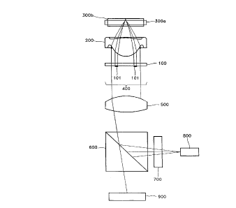
FIG. 7A as a schematic diagram of an optical pickup device adopting the
objective lens device according to a first embodiment of the present
invention,
where the light focused states with respect to thin and thick discs are
compared.
FIGS. 7B and 7C are enlarged views of the focal points shown in FIG. 7A for
thin
discs and thick. discs, respectively. As shown in FIGS. 7B and 7C, the
objective
lens 200 is moved to focus the light on either thin or thick disc.
FIG. 8 is a perspective view of an objective lens 200 and a light controlling
member 100 as .light controlling means.
In FIG. 7A, a reference numeral 300a represents a comparatively thin
information recording medium, e.g., 0.6mm thick disc, and a reference numeral
300b represents a comparatively thick disc, e.g., l.2mm thick disc. It should
be
noted that the diameter of thin and thick discs can be same. Also, the bottom
surfaces 'of the discs can be located in either a different plane or in the
same plane
depending on the disc holder mechanism (not shown) for supporting and rotating
the discs 300a and 300b during operation. The drawing has been modified to
show
the difference in the thickness. The laser light passes through an aperture in
the
disc holder, as is conventional.
A general objective lens 2~~0 is positioned in front of disc 300a or 300b.
The objective lens 200 having a predetermined effective diameter focuses an
CA 02202288 1997-04-09
14
incident light 400 from a light source 900 and receives the light reflected
from disc
300a or 300b. As shown in FIG. 9, there is provided a light controlling member
100 in the rear of the objective lens 200, which is a feature of the present
invention. The light controlling member 100 is transparent and has a light
controlling film ,101 of an annular shape for suppressing, such as blocking or
scattering, the incident light on its surface. The outer diameter of light
controlling
film 101 is smaller than the effective diameter of objective lens 200. The
light
controlling member is made of glass or plastic. Cr, CrO, or Ni, for example,
can
be used as the light controlling film 101. Alternatively or additionally, any
of the
surface irregularities discussed below with reference to FIGS. 12-17 could be
used
on the light controlling member.
A collimating lens 500 and a beam splitter 600 are provided between light
controlling member 100 and light source 900, as shown in FIG. 7A. A focusing
lens 700 and a photodetector 800 are provided along the travelling path of the
light
reflected from beam splitter 600. Here, the photodetector 800 is basically a
quadrant structure.
In the optical pickup device having the aforementioned configuration
according to the present invention, the light controlling film 101 suppresses
among
the incident light beams 400, the light beam 402 of the intermediate region
passing
through the region between the near axis and the far axis regions, thereby
transmitting only the light beams 401 and 403 passing through the near and far
axes
regions, as shown in FIG. 9. For example, a light controlling film 101 made of
Chromium ~ (Cr) would block the light beam 402 from passing through the light
controlling member 100. Moreover, the light beam 402 can be scattered,
reflected,
diffracted or refracted depending on the surface roughness of the light
controlling
film 101.
The light controlling film 101 having the above-described function is
directly coated on one surface of objective lens 200, as shown in FIG: 10. As
shown in FIG. 11, the light controlling film 101' may be modified, in its
shape to
have a polygonal shape such as a square shape or a pentagonal shape as shown
in
FIG. 16, rather than a circular shape. Moreover, an additional light
controlling
film 101 or 101' can be provided to define the near axis region depending on
the
CA 02202288 2000-03-29
thickness of a disk. For example, the objective lens is optimized to a thin
disk and a
corresponding near axis region should be defined. Therefore, additional light
controlling film
or groove can be provided to define an appropriate intermediate region for the
thin disc
according to its thickness. In FIG. l OB, an additional annular light
controlling groove 102'
5 is added in order to optimize a disc having a thickness of 0.9mm. Thus, the
objective lens 200
can be used for discs having thickness of 0.6mm, 0.9mm, or 1.2mm, for example.
FIGS. 12A and 12B illustrate an objective lens according to a still another
embodiment of the present invention. FIGS. 13 and 14A are a perspective view
and a front
view of the objective lens shown in FIG. 12A, respectively. In these
embodiments, there is
10 provided a light deflecting means 102 as the light controlling means in
objective lens 200'.
In other words, a structural pattern, i.e., a light controlling groove 102a of
an annular shape,
for partially blocking, diffracting, refracting, or scattering the incident
light, is provided in the
initial light receiving side (FIG.12A), or on the light emitting side (FIG.
12B) of the obj ective
lens 200'. Moreover, the grooves 102a can be provided in both sides of the
objective lens
15 200'. Alternatively, the light deflecting means 102 can take the form of a
projection or
wedge-shaped rib 102b as shown in FIG. 15K, for instance. The wedge-shaped rib
102b can
also be placed on either side, or both sides, of the objective lens 200'. The
outer diameter of
light controlling groove 102a or light controlling wedge-shaped rib 102b is
smaller than the
effective diameter of objective lens 200'.
Like the aforementioned light controlling film 101, the light controlling
groove 102a
or wedge-shaped rib 102b is provided in the light region between the near axis
and the far axis
and functions to redirect (e.g., reflect, refract or scatter) the incident
light in a direction
irrelevant to the light focusing or suppress (e.g., block) the incident light.
The objective lens 200' can be manufactured by a general high-pressure
injection
molding method (not shown) or a compression molding method, as shown in FIGS.
15H through 15K, using a mold having a pattern corresponding to the wedge-
shaped rib
102a.
The lower mold 1002a has a pattern having one or multiple grooves 103a formed
in
correspondence with the light controlling rib 102b for dispersing the light in
the intermediate
CA 02202288 2000-03-29
16
region, as shown in FIGS. 1 SA and 15B, so that the fabricated lens is
provided with a stepped
or wedge-shaped light controlling means protruding on the surface of the lens,
but was
receded as a groove in the description of FIG. 12A above or a light
controlling means having
a diffraction lattice. The groove 103a is formed at the intermediate region
between the near
axis region and the far axis region. Also, the light controlling means 102 may
in the
alternative be engraved, etched or scratched on the surface of the lens. As
shown in FAGS.
1 SC and 15D, an uneven surface formed by an erosion or etching treatment in
the portion K
comprises the light controlling means 102 of the lens according to another
embodiment of
the present invention.
FIGS. 15E through 15G illustrate various examples of the uneven surfaces
(rough,
toothed, jagged surfaces) for forming the light controlling means 102, which
may be
composed of just one form of surface unevenness or combination of types.
In FIG. 15F, the light controlling means 102 may have an evenly-stepped shape
forming grating pattern to diffract the incident light in the intermediate
region. The grating
pattern has a pitch S which is less than approximately 200 ,um for a laser
wavelength
of 650nm.
FIG. 15H shows a lens material 200m such as glass or plastic is interposed
between
the upper mold 1001 and the lower mold 1002a. As shown in FIG. 15I, the upper
mold 1001
and the lower mold 1002a are brought close to each other to compressively mold
the lens
material 200m. Then, as shown in FIG. 1 SJ, the upper mold 1001 and the lower
mold 1002a
are separated and the objective lens 200n is obtained.
The light controlling groove 102a is preferably formed for the bottom surface
of the
objective lens 200' to be oriented by a predetermined angle B with respect to
perpendicular
of the optical axis, as shown in FIG. 14B. The light of the intermediate
region, reflected from
light controlling groove 102a, is preferably scattered or reflected in a
direction not parallel to
the optical axis.
FIG. 16 is a front view of an objective lens having a light controlling groove
as a light controlling means, where a light controlling groove 102' of a
CA 02202288 1997-04-09
17
square shape is formed in objective lens 200' according to still another
embodiment
of the present invention.
Light controlling groove 102" can be formed of a polygonal shape such as
a square shape. Moreover, the objective lens can be modified to have more than
one light controlling groove to control the incident light. It is also
possible to use
any of these surface irregularities (e.g., groove, rib, toothed, rough and
jagged) on
a separate transparent member such as the light controlling members 100.
In the above embodiments, a convex lens was used as the objective lens 200
or 200', which might be replaced by a planar lens using a diffraction theory,
such
as a hologram lens or a Fresnel lens. Specifically, when the lens is provided
with
light controlling means, an annular or square light controlling groove 102" is
formed in a plane lens, as shown in FIG. 17, or a separately fabricated light
controlling film 101 having an annular or square shape is fixed or coated, as
shown
in FIG. 18. Light controlling groove 102" transmits the light 402 of the
intermediate region without diffraction. Otherwise, light controlling groove
102"
reflects light in the intermediate region in a direction irrelevant to the
light
focusing. Thus, the light 402 of the intermediate region is prevented from
reaching
the light spot of a disc.
A light controlling film lOl. shown in Fig. 18 absorbs, scatters and/or
reflects the light, 402 of the intermediate region, which is incident onto
plane lens
200", prevents the light 402 of the intermediate region from reaching the
light spot
of a disc. For example, when a dark color paint is used as a light controlling
film,
the film absorbs the light. Also, the light controlling groove or the light
controlling
film shown in FIGS. 17 and 18 can be modified to have more than one annular
groove or film depending on the thickness of a disc.
It should be noted that the lens device structure described above is not
limited to an objective lens used in an optical pickup device.
FIG. 19 shows the size of the light spot on a l.2mm thick disc, as obtained
by the above embodiments. The objective lens adopted herein has an effective
diameter of 4mm, a diameter of the near axis region of 2mm and that of the far
axis region from 2.4mm to 4.Omm. Thus, the light controlling means blocks the
light beams ranging from 2.Omm to 2.4mm in diameter: The inner diameter of
CA 02202288 1997-04-09
18
light controlling means having annular shape can be changed to be in the range
of
2.0 to 3.Omm to optimize the focusing spot in the disc. Also, the inner
diameter
and the width of the light controlling means can also be between 1.1 to l.4mm
(such as l.2mm) and between 0.1 and 0.25mm (such as O.lSmm), respectively.
Other ranges are possible depending on system considerations.
In the light spot formed under the above conditions, as the result of the
measurement, the diameter of the llight spot at a point of 1/e~ ( ~ 13 % ) of
the
central light intensity was 1.3~cm. Compared to the device shown in FIG. 5,
which
does not adopt a light controlling film, the light amount of the portion "B"
shown
in FIG. 5 is reduced by more than i'0% in the case of the device according to
the
present invention, which adopts a light controlling filin.
FIG. 20 shows the size of the light spot on a comparatively thin disc, i.e.,
a 0.6mm disc, under the above-described conditions. According to the
measurement, the diameter of the light spot at a point of 1/e2 ( ~ 13 % ) of
the
central light intensity was 0.83~cm.
As described above, according to the present invention, a light spot can be
formed on a disc at an optimal state. As shown in FIG. 7A, the light reflected
from disc is transmitted through the objective lens 200, the light controlling
member 100 and the collimating lens 500 and is reflected from the beam
splitter
600 to then be transmitted through the focusing lens 700 to reach the
photodetector
800 where it is detected and convert~.d to an electric signal. The
photodetector 800
is for obtaining a focus error signal by astigmatic aberration and is a
generally a
quadrant detector.
Hereinbelow, the characteristics of the photodetector 800 in the optical
pickup device according to the present invention will be described in detail.
As shown in FIGS. 21 and 22, a spot formed in the center of the
photodetector 800 has central regions 901a and 90Ib corresponding to the light
of
the near axis region and peripheral regions 902a and 902b corresponding to the
light of the far axis region. The "a" and "b" designations signify a light
spot on
a thick disc and on a thin disc, respectively. Specifically, FIG. 21 shows the
case
of a comparatively thick disc, e.g., a l.2mm disc, and FIG. 22 shows the case
of
a comparatively thin disc, e.g., a 0.6mm disc. The change in diameters is
CA 02202288 1997-04-09
19
insignificant in the central region 901a by the light of the near axis region,
irrespective of the disc thickness. However, the change in diameters is
significant
in the intermediate region 903a, non which the light is blocked by the light
controlling member 100.
First, referring to FIG. 21, the central region 901a corresponding to the
near axis region is in the center of the photodetector 800 and the peripheral
region
902a surrounds the photodetector 800. The intermediate region 903a between the
central region 901a and the peripheral region 902a is the portion from which
the
light is eliminated by a light controlling member. Since the peripheral region
902a
and the intermediate region 903a are substantially enlarged by spherical
aberration
in this example where the reflective surface of the disc is near the paraxial
focus,
only the light of the near axis is used in reproducing information from a
l.2mm
thick disc.
Referring to FIG. 22, both the central (i.e., near axis) region 901b and the
peripheral (i.e., far axis) region 902b are formed on the detection surface of
the
photodetector 800 because, in this example, the reflective surface of the thin
disc
is near the minimum circle of.the beam focus. In other words, all of the light
of
the near and far axes regions are used in reproducing information from a thin
(0.6mm) disc, excluding the light of the intermediate region which is
eliminated by
a light controlling member. Here, the diameter of the near axis region 901b,
being
paraxial, maintains a relatively constant value irrespective of a disc type.
As described above, in order to read information from discs having different
thicknesses, the optical pickup device according to the present invention
adopts a
photodetector 800 devised so as to receive only the light of the near axis
region in
reading information from a thick disc and receive the light of the near and
far axes
regions in reading information from a thin disc. Therefore, when a thick disc
is
used, a signal corresponding to the light of the near axis region is obtained.
When
a thin disc is used, a relatively higher intensity signal, corresponding to
the light
of the near and far axes regions, is obtained. ,
FIG. 23 shows another type of photodetector 810, which has an octahedron
or eight-segment structure wherein a second detection region 812 is provided
around a first detection region 811 which is centrally located and equivalent
to the
CA 02202288 1997-04-09
quadrant photodetector shown in FIG. 21. Here, first detection region 811
consists
of four square first-light-receiving elements A 1, B 1, C 1 and D 1, and
second
detection region 812 consists of four L-shaped second-light-receiving elements
A2,
B2, C2 and D2.
5 A focus error signal obtained by using the octahedron photodetector 810 is
shown in FIG. 30, when information is read from a thick disc. Here, the signal
from the first light receiving region 811 only is indicated by a solid line A
and that
received from both the first and second light receiving regions 811 and 812 is
indicated by a dotted line B.
10 FIGS. 24 - 26, and 27 - 29 show .the light receiving states of the
photodetector, when a thin disc (digital video disc) is used, and when a thick
disc
(compact disc) is used, respectively.
The first detection region 811 has dimensions such that the size of the first
region 811 should be optimized to receive the light from the near axis region
15 without loss when information is read from a thick disc, and not to receive
the light
from the far axis region. Additionally, the first and second detection regions
811
and 812 have dimensions such that the light beams of the near axis and far
axis
regions are all received when inforniation is read from a thin disc, as shown
in
FIG. 24. When information is read from a thick disc, the light of the far axis
20 region impinges on the second light receiving region 812, as shown in FIG.
27.
FIGS. 24, 25 and 26 show the light receiving states when an objective lens
is in focus with respect to a thin disc, when the objective lens is positioned
too far
from the disc, and when the objective lens is positioned too near the disc,
respectively. Similarly, FIGS. 27-29 show the light receiving states when an
objective lens is in focus with respect to a thick disc, when it is positioned
too far
from the disc, and when it is positioned too near the disc, respectively.
In the photodetector 810 having the aforementioned structure, the entire
signal, i.e., that from both the first and second Iight receiving regions 811
and 812,
is used in reading information from a thin disc, and only the signal from the
first
light receiving region 811 is used in reading information from a thick disc.
FIG. 30 shows the focus error signal changes by the signal from the first
light receiving region (solid line A) and by the entire signal from the first
and
CA 02202288 2000-03-29
21
second light receiving regions (dashed line B) when information read from a
thick disc. The
difference between the shapes indicated by the solid line A and the dotted
line B comes from
the amount of scattered light in a thick disc. In the octahedron photodetector
810, scattered
light that is originated from a large spherical aberration of the thick disc
in detected mainly
by the outer photodetector 812. The scattered light detected by the outer
photodetector 812
causes increase in the amplitude of the focus error signal which resulted an
unstable focus
error signal as shown in the dotted line B. And in turn, when only the
detected light
impinging on the inner photodetector 811 is used, it can be possible to reduce
the effect of
the scattered light on the S-curve as shown by the solid line A. In practical
use, the focus
error signal as denoted by A is better than B since it has a single zero-cross
point for the focus
error signal and the symmetry of the signal at the zero-cross point are
important characteristics
to identify the on-focus position of a objective lens.
As understood from the above, when information is read from a thick disc, the
focus
error signal components are obtained by using only the light of the near axis
region, thereby
obtaining a stable focus error signal as shown in FIG. 30.
As described above, in the focus controlling method of the objective lens
device and
optical pickup device adopting the same according to the present invention
which has a size
reducing effect of the light spot, i.e., the light amount of the portions "B"
of FIG. 5, and a
focus error signal stabilizing effect, since only a single focus error signal
is generated
irrespective of a disc thickness, an additional focus control means is not
required in order to
use the different thickness discs.
Also, the magnitudes ofthe detected focus error signals are different
depending on the
disc thickness. In other words, as shown in FIG. 31, all of the light of the
near and far axes
regions reach a photodetector in the case of a thin disc, and only the light
of the near axis
region reaches the photodetector in the case of a thick disc, thereby easily
discriminating the
disc type.
The operation of discriminating the disc type will now be described in detail
with
reference to the flowchart of FIG.32.
If a thin or thick disk is inserted (step 500), focus current (which controls
CA 02202288 2000-03-29
22
the position of the objective lens relative to the disc) is increased or
decreased to discriminate
the range of an objective lens, i.e., the type of a disc, as shown in FIG. 33.
The objective lens
is moved up and down m times (m=1, 2, 3,...) within its range of focus
adjustment, thereby
obtaining a sum signal from the photodetector (adding together all signals
from each of the
S eight quadrants) and a focus error signal (Sf) (step SO1). Since a quadrant
photodetector is
used, the focus error signal is obtained by a conventional astigmatic method
such as disclosed
in U.S. Patent No. 4,695,158 to Kotaka et al, for example. Being conventional,
an
explanation thereof will not be belabored. Experimentally it has been shown
that the
amplitude of the focused error signal for a thin disc reproduction is four
times that for a thick
disc reproduction, that the light intensity is enough for compatibility with
both disc types and
that a focus error signal stabilization is realized.
The amount of spherical aberration is reduced by the above-described method to
reproduce a signal recorded onto a disc. However, the spherical aberration is
larger than that
of the optical pickup for the conventional compact disc player, thereby
resulting in the
1 S deterioration of a reproduction signal. Therefore, it is preferable that a
digital waveform
equalizer is used, as shown in FIG. 36, which, assuming an input signal fi(t),
produces an
output signal fo(t) in accordance with
fo(t) = fi(t+T) -K[fi(t) +fi(t+2T)]
where T i s a predetermined delay time, and K is a predetermined amplitude
divider, as shown
in FIG. 32 (steps 506 and 517).
Once the focus error signal Sf and the sum signal are obtained (step 501 ), it
is
determined whether the focus error signal S f is greater than a first
reference signal for a thin
disc (step 502). At this time, the sum signal may be also compared with the
first reference
signal in accordance with the design conditions.
As shown in FIG. 34, if the first reference value is less than the focus
signal Sf or the
sum signal, it is determined that the disc is thin (step 303) and focusing and
tracking are
continuously performed (step 104) in accordance with this determination,
thereby obtaining
a reproduction signal (step 305). The reproduction signal passes through a
waveform
equalizer (step 506) for a thin disc to obtain a waveform equalizing signal
(step 507).
CA 02202288 2000-03-29
23
However, if the first reference value is greater than the focus error signal S
for the sum signal,
it is then determined whether the focus error signal is greater than the
second reference value
corresponding to the thick disc (step 513).
As shown in FIG. 35, if the first reference value is greater than the focus
error signal
Sf or the sum signal and the focus error signal S f or the sum signal is
greater than the second
reference value (step 513), it is determined that the disc is thick (step 514)
and focusing and
tracking are continuously performed (step 515), thereby obtaining a
reproduction signal (step
516). The reproduction signal passes through a waveform equalizer (step 517)
for a thin disc
to obtain a waveform equalizing signal (step 518).
If the focus error signal Sf or the sum signal is smaller than a second
reference signal,
an error signal is generated (step 523). The focus error signal and the sum
signal can be used
to discriminate the disc type clearly and this method using both signals
reduces the
discrimination error.
As described above, the lens device according to the present invention has
various
advantages as follows.
The lens device according to the present invention adopts a light blocking or
scattering
means which is simple and easy to fabricate, instead of a complex and
expensive hologram
lens. Also, since the light can be used without being separated by a hologram
lens, the lens
device has a higher light utilizing efficiency than that of the conventional
device. In addition,
since a very small beam spot is formed, the performance of recording and
reproducing
information can be enhanced. Since the lens device with a light blocking,
refracting,
diffracting or scattering means has a single objective lens, it is very simple
to assemble and
adjust the optical pickup adopting the lens device. Also, since a signal which
can
discriminate the disc type is always obtained regardless of the thickness of
the discs,
additional means is not required for discriminating the disc type. In
contrast, the
conventional device using hologram has to adopt additional means to
discriminate some
signals because the device generates multiple signals. Among xhe multiple
signals, one is
used for thin discs and another is used for thick discs.
While the invention has been particularly shown and described with
CA 02202288 1997-04-09
24
reference to a preferred embodiments thereof, it will be understood by those
skilled
in the art that various other changes in form and details may be made therein
without departing from the spirit and scope of the invention. For instance,
the
relative position of the discs in the light path can be altered, thereby
changing the
spot patterns and consequently the details of .the various methods using the
electrically converted spot patterns.
Industrical ApplicabilitX
The present invention can be utilized in an optical system adopted in the
fields of recording media for record.inglreproducing video or audio, data.