Note: Descriptions are shown in the official language in which they were submitted.
CA 02211268 1997-07-23
WO 96J23154 PCT/US95/14212
COMPRESSOR VALVE
Bacl~ I ~ulld of the Invention
The present invention pertains to valves which may be used for intake or
eYh~-lct of gases from con-p~ssc)l~, and more sre~ifit~lly, to ~wi~rocaLing
CO111~ 5CIl~. The operative portion of such a co~ )r~ssor ineludes at least one piston
and cylinder assembly, and the intake and eYh~llst valves are typically located at or
near the cylinder head. It is known to use the same form of valve for both intake and
h~llst, simply reversing the position of the valve for the two uses, res~ ely.
One such valve is tli.cçlosed in ~cci~nP~'s prior U.S. Patent No. 3,536,094.
This valve has two annular valve elementc arranged conc~ntri~lly with respect toeach other and to the valve as a whole, and each reciprocating between stop surfaces
and valve seating surfaces formed"es~;li~rely, on opposed plates forming the valve
case. Each valve elemPnt is biased closed, i.e. toward its seating surfaces by aplurality of springs cil~;ulllft;lclllially spaced thereabout. In an ~lte~n~t~ emboflimçnt
the two annular valve çlçmPntc are i.~ ge~t~cl by h~ ol-nPcting them with small
radially eYt~Pn~lin~ webs.
In some of ~cci~nPe~s more recent commercial emb~imP-nt~ of this valve, the
plate defining the seating surfaces has a plurality of tabs or flanges ç~tPn~ling
inwardly ~ ent the outer fli~mPter of each ,~s~Li~e set of seating surfaces, andcircumferentially spaced thereabout, to guide the seal rings in their reciprocatory
movement.
In such prior valves, it is very preferable that the valve elements be formed
of a hard plastic m~teri~l, rather than metal, for reasons more fully explained in the
prior patent srecific~tion.
Although ~Cignpe~s prior valves according to U.S. Patent No. 3,536,094
continue to be highly succes~ful, they tend to be directed primarily to specialty
Illalkt;ls. One reason for this is that the hard plastic m~teri~l of which the valve
elements are formed must be of a relatively expensive, high impact, heat, and
~ chemical resistant m~tçri~l, and the valve elemPntc are of such various sizes that they
3~ must be custom made; the sizes of the valve çkPmPnts must be tailored to various size
valves.
CA 02211268 1997-07-23
W O96/23154 PCTnUS95/14212
There have been suggestions in the prior art to utilize a plurality of poppet-
type valves, inco")o~dled in a single valve case, for such colllp.essor intake and
eYh~11ct An PY~mr1e is described in U.S. Patent No. 4,489,752 to DeminQ1~i
~i~oriç~11y, poppet valves have only been succeccful in low dirrercn~ial
prt;s~ur~ applic~tions (300-400 psi) at relatively low speeds (30~400 cGll,pressor
strokes/minute). The valve PJemPntc of tr~lition~1 poppet valves are more or less
mushroom ch~ped, with the head of the mushroom defining the sealing surface for
engagement with the valve seat, and the stem of the mushroom being utilized for
g11i(l~nce of the valve element in its reciprocatory movement.
It is desirable, in these valves, to minimi7P ples~ulc drop and dirrere"lial
pr~ssule. High ~lirrc.cnLial pr~s~. le can cause extrusion of the valve e1emPnt into the
seat flow holes. Achieving low p,cssu,c drop typically r~uilcs a relatively high"lift" or ,eci~,ocal~ry stroke of the poppet. The high lift can work with the seat flow
hole di~mPtP.r to provide a relatively large available flow area for the gases.
~PAucin~ the seat flow hole ~ mPter can help to prevent such extrusion, but only at
a penalty of loss of efflcie~ncy. Thus, relatively large rli~mPtPr seat flow holes are
typically used, and even then, they must be acco",p~l-iecl by a relatively high poppet
lift, as reductions in lift likewise tend to decrease efficiency. In short, there is a
balancing act involved in l1ti1i7.ing poppets for this type of application, and it has
traditionally been b~l~nce~ sllcce~fully only in the aforementioned low differential
pres~u,e and low speed applications.
The Demin~l~i patent seeks to address some of these problems by reducinp the
overhang of the tr~lition~l mushroom form and by a special aerodynamic shape of
the upper part of the poppet or valve e1ement
The current and a~parellt future trend in the colllpr~ssor art toward higher
operational speeds would appear to further militate against the use of poppet-type
valves with such co,~ c~so,~.
S~ ry of The I~ liJll
However, in accord with the present invention there has been devised a unique
form of multiple poppet type valve which can be produced much less expensively than
.~s~iPnee~s prior valves, can be used in high speed coll-pr~ssol~, and allows the
CA 02211268 1997-07-23
W O 9612315~ PCTnUS9~14212
poppet lift to be reduced to one-half of what would norrn~lly be required (with
conventional prior art yoppel~) in order to obtain a given flow area for the gases.
More sper~ ly, a co"l~lessor intake or r~}~ valve according to the
present invention compri~s a seating plate and a guard plate releasably ~ rhYl in
5 opposed relation to make up the valve case. The seating plate has a plurality of
clusters of holes e~t~.n(lin~ from an outer side of the seating plate thereinto. The
holes of each cluster are arranged along a ~ eclive ring-~h~peA, pr~f~ldbly circular
or annular, locus, and col,l-llun,cate with lc;~ ;Live seating surf~ces opening through
the inner side of the seating plate. The clusters are spaced from one another
10 ~ ;ul~fwtilllially and/or radially relative to the case as a whole; they are not
conrPntric .
The guard plate defines a r~eeLive stop surface generally opposed to but
spaced from the seating s~ r~ associated with each such cluster of holes. The
guard plate also has flow passages th~ç~Lhr~ugh from the inner to the outer side15 thereof and co".~ i~ting with the spaces between the stop surfaces and the seating
s~ res. A ~s~cLive valve elçm~nt or poppet is ~oci~t~A with each cluster, and
is collespolldingly ring-shaped, preferably annular. These po~L~ or seal rings are
reciprocable between the stop surfaces and the respective opposed seating surfaces
and have sealing surfaces sized and shaped to engage and seal against the le~ec;Li~e
20 seating surfaces. A plurality of springs carried by the guard plate each engages a
respective one of the seal rings to bias the seal ring toward the respective sealing
surf~
Rer,~ e,, when the valve is open, i.e. when the seal rings are against their stop
surfaces and spaced from their seating surfaces, gases can flow both interiorly and
25 exteriorly of the seal ring, a given flow area can be provided with a~p,. ,~imately half
the normally required lift or travel.
The seal rings need not be fully customized, but can be off the shelf items, or
m~rllin~i from off the shelf items, thereby decreasing production costs.
Furthermore, a single size of seal ring can be used not only throughout a given valve,
30 but for a range of valves of dirrelent sizes, simply adding additional poppets to larger
sized valves in the range.
Rec~llse gases can flow along both the inner and outer ~ m~tçrs of the seal
CA 02211268 1997-07-23
W O96/23154 PCTrUS95/14212
rings, they tend to be self C~ te~;ng, and will not or~inalily require positive gui~n~
in their ~;iplocdl~l~ movement. However, the ~ e spring for each seal ring,
which is plereldbly eoaxial thelGwiLh, ean provide additional me~h~nic~l g~ n~-eFurthermore, in some elllb~l;~ nt~, guide flanges may extend inwardly adjacent the
S seating surfaces to provide posilive mech~nic~l gui-l~n~-e for the seal rings throughout
their entire travel or stroke. If the seating surfaces and guide flanges are formed on
se~ lp seat members IllJunLed in the seating plate, the seal rings will be self
ce~ -g with respect to their seats, even if the seat ,llenlbel~ should become laterally
pl~rerl with respect to the main body of the seating plate. This ~ a~es one of
the problems previously encounlel~d in aLL~ Lillg to provide replaceable seat
members in poppet-type valves. Such a sP~ seat member can be firmly fixed in
the longit~ in~l directional mode by use of a resilient loading device collll,lessed
beLween each seat member and the guard plate to urge the seat member tightly into
a respective recess in the seating plate.
Various objects, features and advantages of the invention will be made
~enl by the following det~ d description, the drawings, and the claims.
BFUllEF DESCEU[lrrION OF 'l'Hh' DR1~VV~GS
Fig. 1 is a lon~it~ldin~l cross-section~l view of a first embodiment of the
present invention taken along the line 1-1 in Fig. 2.
Fig. 2 is a top plan view of the device of Fig. 1.
Fig. 3 is a bottom plan view of the device of Pigs. 1 and 2.
Fig. 4 is a partial longitllriin~l cross-section~l view of a second embodiment
of valve according to the present invention.
Fig. 5 is a partial top plan view of the embodiment of Fig. 4.
Fig. 6 is a detailed view of a modific~tion of the embodiment of Figs. 1-3
showing a removable seat member.
Fig. 7 is a view similar to that of Fig. 6 showing a second embodiment of the
modified seat member, and colr~ ding changes in the guard plate.
Fig. 8 is a view taken along the line 8-8 of Fig. 7 with the spring and seal
ring removed.
CA 02211268 1997-07-23
WO 96/23154 PCT/US95/14212
DETAILED DESCRIPIION
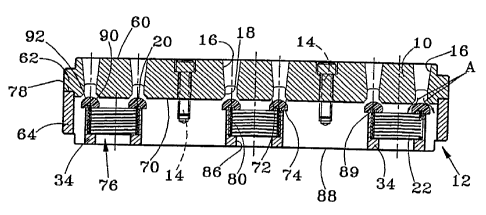
Figs. 1-3 ill~lstr~te a first embo~im~nt of co~ cssor valve accor~ g to the
present invention. As shown, this, and all the other e~ nt~ osçd herein,
is nriPnt.oA for use as an intake valve. However, it would be possible to use precisely
5 the same form of valve as an eYh~llst valve by simply l~ g its on~nt~tion,
vertically as shown in the drawings, as is well known in the art. The valve comprises
as seating plate 10 and a guard plate 12 secured lo~ell,rr in o~ ing relation byscrews 14 to form the valve case. Plate 10 has its thi~kn~ss reduced at the periphery
of its outer side 60 to form an annular, radially projecting flange 62. Similarly, plate
10 12 has its thickn~-ss reduced ~ nt the ~li~hely of its outer side to form an
abutting radially projecting annular flange 64 of like width as flange 62 and aligned
therewith. Thus, the flanges 62 and 64, in the assembly, jointly form a flange
whereby the valve case may be mounted in, for PY~mrle, the cylinder head of a
reciprocating gas col-lp~ssor, as is well known in the art.
Col.lpaliilg Figs. 1 and 2, it can be seen that the seating plate 10 has a
plurality of clusters of holes 16 ~Lelldillg longit~lflin~lly into the plate from its outer
side 60. More specifically, each such cluster compri~es three holes 16 in the form
of arcuate slots lying along a common circular or annular locus. There is a central
cluster 66. Spaced radially ou~w~dly from cluster 66, and circumferentially from20 one another, are other clusters 68. The slots 16 are not only arcuate, when viewed
in plan, but, as viewed longit~ in~lly in Fig. 1, have their widths t~ring inwardly
from the outer side 60 of plate 10 toward its inner side 70. The slots 16 ~~ ,nale
short of inner side 70, and the slots 16 of each cluster intel~ecl a common annular
a~c;llur~ 18 which opens through the inner side 70 of plate 10, and the inner portion
25 of which defines seating surfaces, more spe~-ific~lly, an inner annular seating surface
72 and an outer annular seating surface 74, ~dj~nt the inner and outer ~ mP~ters~
respectively, of annular al)~llu-~ 18. These seating sllrf~çs are preferably tapered
away from each other as they progress toward the inner side 70 of plate 10. Theymay, for example, define either spherical or conical loci. However, they could be
30 flat, downwardly facing surfaces.
The guard plate 12 includes a plurality of cylin~lric~l guides 34. The interior
of each guide 34 provides a port 76 generally aligned with a respective one of the
CA 02211268 1997-07-23
W O96/231S4 PCTrUS95/14212
clusters of slots 16 and its re~ e annular apelLule 18. The inner side 78 of rim35 of plate 12 abuts the inner side 70 of plate 10, but guides 34 do not. Except for
guides 34 and s~-fficient h~t~,co~ cting members 36 to connect cylinders 34 to the
plate rim 35, plate 12 is completely open.
Each of the ports 76 has two sections or portions: a relatively large ~ , . .ele~
portion 80 sized to slideably receive a helical coil spring 22, and a smaller ~ m~r
portion 86 opening oulwal-lly through the outer side 88 of plate 12. Between portions
80 and 82, there is formed a shoulder on which spring 22 rests, and which serves as
a spring reaction shoulder. The top of guide 34 provides an annular stop surface 89
spaced from the inner side 70 of plate 10.
An annular seal ring 20 is lccipr~cable b~lween each of the annular stop
surf~ces 89 and the r~s~cli~e seating surfaces 72 and 74. The side of ring 20 which
faces and, when the valve is closed, abuts seating s--rf~ees 72 and 74, has sealing
surfaces 90 and 92 ~ljacent its inner and outer ~ respectively, and inclined
toward each other, to generally COllt; .~nd to the taper of seating surfaces 72 and 74.
Plerel~bly, if ~.ulr~ces 72 and 74 define spheric~l loci, sllrf~res 89 and 92 define
mating spherical loci; if sulr~ces 72 and 74 define conical loci, surfaces 89 and 92
preferably define mating conical loci; etc. However, other arrangemellls are possible.
For example, surfaces 72 and 74 could define conical loci, with surfaces 89 and 92
defining spherical loci tangent to the lcs~e.;live conical loci.
The other side of ring 20 is generally planar for abutment with stop surface
89. However, approximately midway between its inner and outer ~ meters~ that side
of ring 20 is provided with an annular recess which receives one end coil of therespective spring 22. Ring 22 can travel b~Lw~n a closed position Pn~ging seating
surfaces 72 and 74, and an open position en~gin~ stop surface 89. As is known inthe art, spring 22 will normally urge ring 20 into its closed position. However,whenever the pres~ulc; in the ~ r~nt end of the colllpl~ssor cylinder, and thus in the
ports 76, is lower than the ple~ul~ of the gas being taken in, i.e. the ~les~uI~; in
slots 16 and ape,lules 18, to a s--fficient degree to overcome the springs 22, the
valves will open. When these pl~ssul~ conditions are reversed, the valves will again
be closed by their springs 22.
The sealing rings or valve elem~ont~ 20 can be m~rhin~d from off the shelf
CA 02211268 1997-07-23
W O961231S4 PCTAUS9~14212
rings of hard plastic, and more sper-ific~lly, of a polymeric m~t~ri~l which is high
impact rP~ t~nt as well as chPmi~l and heat rP~ t~nt All of the rings 20 are of the
same size, and if there is a range of valves similar to that shown in Figs. 1-3, but of
dirl~ L sizes, it is only ~Pce~-y to increase or dec~ease the number of clusters,
S seal rings, etc. to allow for larger and smaller sizes in the valve range. Thus, the
ring size can be standardized not only for a given valve, but for the entire size range.
Other than from its spring 22, each ring 20 lcceives no positive mPrh~nir~l
gui~l~n~e in its travel. However, it is self ~lignin~ with its l~s~~ e seating surfaces
72 and 74 for several reasons. First, because of the construction of guard plate 30,
incoming gas can flow along both the inner and outer ~ m~ters of ring 20 and guide
34, as shown by the arrows A in Fig. 5. This helps to center the ring 20.
Furthermore, as mt~.nti~mP~, there is a substantial amount of g~ nre from spring 22,
which in turn is guided by the inner ~ me.ter of the enclosing portion of cylinder 34.
Finally, once the ring 20 begins to move into ~lignm~nt with its seating surfaces 72
and 74, the tapers of the seating sllrf~es and the sealing sllrf~cçs on the ring 20, will,
so to speak, cam the ring 20 into proper ~lignm~nt with its seating surfaces.
Referring next to Figs. 4 and 5, there is shown a second embodiment of the
invention, which is generally the same as the first embo lim~-nt, except that the holes
40 of the various clusters are cylin~lri(~l, rather than arcuate, and their sides do not
taper along their lengths. The bottom plate 12, spring 22, and seal ring 20 are the
same as in the first emborlim~nt
Fig. 6 shows a mo(~ifir~tif)n which could be applied to any of the above
embo limlqnt~ or other embo-~im~nt~ of the invention, but which, as shown, is applied
to the embodiment of Figs. 1-3. Sp~ifi~lly, the seating plate of Fig. 6 includ~s a
met~llic main body 94, with a plurality of lecesses 96 in its inner side, each recess
being generally aligned with a respective cluster of the arcuate slots 16. Within each
recess 96 is fitted a seat member 50, e.g. of plastic, which defines the inner portions
of the slots 16, as well as the annular a~llule 18, inclutling its seating sllrf~s.
Together, the main body 96 and seat members 50 define a seating plate generally of
the same configuration as that of Figs. 1-3. However, ~ ent the outer ~ m~ter
of its inner side, each seat member 50 has an undercut which receives a resilient
loading device such as an o-ring 52, which is oversized for the depth of the undercut.
CA 02211268 1997-07-23
W O96/23154 PCTrUS95114212
Thus, when the seating and guard plates are fixed togGl}lGl, the o-ring 52 is
co,l,plessed beLween the seat member 50 and the guard plate 12 to firmly urge the
seat member 50 into its recess 96. An advantage of this motlifi~ ~tion is that, if the
seating ~ulr~ces become worn or ~1~m~ged, they can be replaced by repl~ing the seat
5 members 50, without the need to discard the entire seating plate.
Another morlifit~tion of Fig 6 is that three ci,~;w"rtrellLially spaced tabs, one
of which is shown at 100, ~Yten~ l inwardly from the end of guide 34 to plat 10.Tabs 100 are sized to slidably engage the O.D. of ring 20 to provide positive
mPrh~nic~l g~ nce for its travel.
Figs. 7 and 8 show a further modifi~tiQn of the conce~L generally disclosed
in Fig. 6. The main body 94 of the seating plate is identic~l to that of Fig. 6, except
that its seat receiving rGcesses have been widened to receive a modified form 50' of
the seat member. This member is not only wider, but inçludes three flanges or tabs
54 eYten(ling inwardly past the outer seating surface 74. These are positioned to
15 slidably engage the outer fli~met~r of ring 20 to provide m~ch~ni~l guid~n-e
therefor. By placing these guides on the seat Illtlllber 50', it can be ensured that the
ring 20 will always PÇOPG11Y align with its seating surfaces on the member 50', even
if the latter should shift slightly laterally in its recess.
While the forGgoing l~lcsGnt exemplary and cullGnlly prGrelred embo-1im~nt~
20 of the present invention"lulllerous modifications will suggest them~olves to those of
skill in the art. Accordingly, it is int-~nded that the scope of the invention be limited
only by the following claims.