Note: Descriptions are shown in the official language in which they were submitted.
-
CA 022128~4 1997-08-13
W 096/25570 PCTnB96/00236
pAp~RR~n FOR PROTECTING DRYWALL CORNERS
BACKGROUND OF THE lNv~-NllON
The present invention relates to drywall corner-
beads, particularly drywall corner beads having an outer
paper layer. Current building construction techniques
frequently call for the use of drywall sheets, otherwise
called wallboard, to form the surfaces of interior walls.
Sheets of drywall are made by encasing sheets of plaster
with heavy construction paper. The paper provides extra
strength and resistance to tearing and prevents crumbling
of the enclosed plaster. The sheets of drywall are
typically produced in sizes of four feet by eight feet or
four feet by twelve feet. These sheets can be installed
intact or can be cut to custom fit specific interior wall
sizes. When cut, the inner plaster is exposed and is
particularly w lnerable to crumbling or other damage
unless the severed edges can be protected. An exposed
corner, exterior or in'erior, formed by two interfacing
drywall sheets not in the same plane is also susceptible
to damage. Damage can be particularly severe when these
corners involve cut or exposed edges. To overcome this
vulnerability to injury and further reinforce the exposed
corner formed by two interfacing drywall sheets, a
drywall corner bead will generally be installed at that
corner. The corner being reinforced can be either an
interior or exterior corner.
Two types of drywall corner beads are typically
used in reinforcing drywall corners, a paper faced bead,
or paperbead type, and a non-paper faced bead, or nail-on
type. Both the paperbead type and the nail-on type
typically include a strip of metal formed or extruded
into a desired shape, although molded plastic can also be
used. One common example involves forming the metal
strip into a core shape having two flanges and a center
. 35 rib positioned between them. This form of corner bead
will be called a rib-type of corner bead. Another common
type of corner bead has two flanges and a larger curved
CA 022128~4 1997-08-13
W O 96/25570 PCTAB96/nO236
portion or bullnose positioned between them. This type
of corner bead will be called a bullnose corner bead. A
third type of corner bead is an L-shaped type having one
flange longer than the other and an offset rib between
the flanges. Other types of corner beads include a J-
shaped type, a splay-bead type, and a shadow-mold type.
Nail-on corner beads are attached to drywall by
driving nails through the flanges, securing the drywall
trim with the heads of the nails. A joint compound is
then applied to cover the flanges and nail heads. The
compound is sanded and feathered to provide a smooth and
continuous sur~ace from the drywall sur~ace to the center
rib of the formed metal strip.
Paperbeads provide several advantages over
nail-on corner beads. For instance, both paint and joint
compound adhere significantly better to the surface of a
paperbead than to the exposed metal surface of a typical
nail-on corner bead. }~oreover, paint applied directly to
a metal surface is easily chipped after drying. Drywall
corners covered with nail-on corner beads are also more
susceptible to cracking along the edges of the flanges.
Thus, a paperbead provides a better sur~ace ~or paint
adkesion and helps reduce plaster cracking.
Paperbeads differ from nail-on type corner
beads in several respects. First, the paperbead has a
paper strip attached to an outer surface of the formed
metal or plastic core previously discussed. Generally,
portions of the paper strip extend beyond the edges of
the metal or plastic core ~orming wings. The paperbead
is attached to drywall corners by applying a joint
compound to the drywall sur~ace and embeading the formed
metal strip and the paper wings in the compound. A
second, exterior layer o~ joint compound is subsequently
applied on top of the paperbead and allowed to dry. This
exterior layer of joint compound is then sanded and
feathered to form a smooth and continuous surface between
the drywall and the corner bead. The steps o~ applying,
CA 022128~4 1997-08-13
W 096/2~570 PCTnB96/00236
sanding and feathering the exterior layer of joint
compound can be repeated until a smooth surface is
created. Throughout this process, the portion of the
paper strip covering the corner bead, i.e. the center
rib, the bullnose, or the offset rib, is left exposed or
uncovered by joint compound.
The paper surface left exposed on a typical
paperbead may be scuffed, or completely removed during
the sanding and feathering process, thus exposing the
metal surface beneath. Scuffing makes it more difficult
to later obtain a smooth painted surface at the corner
bead because the paper becomes frayed or fuzzy. Also, as
stated previously, paint does not adhere as easily to the
exposed metal surfaces. Therefore, paint applied to any
exposed metal surface will be more easily chipped after
it dries. Moreover, a scuff in the paper surface
produces a break in the line of the corner bead and
reduces the aesthetic benefits of having such a bead.
Joint tape made from paper strips is also used
to cover the joint between two abutting sheets of
drywall. The joint tape is applied to a thin layer of
joint compound covering the joint, covered with an
exterior layer of joint compound and sanded and ~eathered
to form a smooth and continuous surface. As with corner
beads, the joint tape can be subjected to abrasive
contact that can scu~f and tear the joint tape, making it
difficult to obtain a smooth surface ~or painting.
To overcome the problems of scuffing, some
paperbeads provide a surface coating at the exposed
center portion o~ the corner bead to improve the paper's
resistance to abrasion and avoid the problems caused by
scuffing. This type of surface coated paperbead is
disclosed in United States Patent No. 5,131,198. A
surface coatin'g, however, only provides extra resistance
to abrasion at the outer surface of the paper strip. If
this coating is penetrated or removed by the sanding
process, the underlying paper is exposed and is again
,
CA 022128~4 1997-08-13
W 096/25570 PCT~B96/00236
made susceptible to scu~ing. Consequently, the problems
o~ paint adhesion, unsmooth sur~ace finishes and paint
chipping are not avoided. Moreover, the application of a
surface coating at a particular location involves an
additional manufacturing step thereby increasing the cost
of making the product.
Therefore, in view of the above it is an object
of the present invention to provide an arrangement
wherein the paperbead is resistant to abrasion without
the need for a coating.
SU ~ ARY OF T~IE lNv~;N~LloN
The present invention provides an improved
paperbead that eliminates the need to provide a localized
surface coating while immllnizing any and all exposed
paper to scu~ing or other abrasive damage. In
accordance with present invention, the improved paperbead
includes an elongated core having an outer sur~ace. A
paper strip is bonded to the outer surface of the core.
The paper strip is made from a stock paper impregnated
with a latex to a relatively uni~orm concentration
throughout its thickness.
The paper strip discussed herein maintains a
uni~orm and increased strength throughout its thickness,
thereby making it resistant to scuffing even if its outer
layers are removed by sanding or other abrasive contact.
This uniform strength is obtained by uniformly
penetrating the entire thickness o~ the paper with a
latex. In a pre~erred embodiment, the paper strip
includes a stock paper impregnated with a latex which is
cross-linked. The resulting paper is substantially
stronger than papers currently used in drywall corner
beads. Furthermore, the increased resistance to abrasion
is a property~of the paper itself, rather than just a
localized shield as provided by surface coatings.
There~ore, even i~ the surface o~ the paper strip is
sanded away, the inner layers continue to resist
CA 022128~4 1997-08-13
W 096/25570 PCTnB96/00236
abrasion. A smooth surface is therefore maintained as
the paper strip resists scuffing. The paper strip also
provides an excellent surface for paint adhesion.
The present invention also provides a method
' 5 for joining abutting sheets of drywall by utilizing the
paper strip disclosed herein as joint tape. First, the
paper strip is applied to a layer of joint compound, such
as joint cement or spackle. A second layer of joint
compound is then applied, covering the outer surface of
the paper strip. Excess joint compound is removed and
the compound is allowed to dry. The joint compound is
then sanded and feathered to form a smooth and continuous
surface between the abutting sheets of drywall. Due to
its increased strength properties, the paper strip is
thinner than other currently available joint tapes.
Consequently, the installation process requires less
joint compound. As a result, the joint compound dries
faster and less sanding is required to finish the joint.
The paper strip which forms the joint tape can be
subjected to adverse abrasion during the sanding process.
The added strength of the paper strip prevents it from
being scuffed by this adverse abrasion at all levels o~
the paper's thickness.
2 5 BRIEF DESCRIPTION OF DRAWINGS
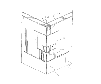
FIG. 1 is a perspective o~ an exterior corner
with a preferred embodiment of the invention applied
thereto and with portions broken away and in section.
FIG. 2 is a preferred embodiment of the
invention showing a cross section through an exterior
corner with a rib type of paperbead applied thereto.
FIG. 3 is a preferred embodiment of the
- invention showing a cross section through an exterior
corner with a bullnose type o~ paperbead applied thereto.
FIG. 4 is a preferred embodiment of the
invention showing a cross section through a corner with a
L-shaped type of paperbead applied thereto.
CA 022128~4 1997-08-13
W 096/2S570 PCT~B96/00236
FIG. 5 is a preferred embodiment of the
invention showing a cross section through an interior
corner with a bullnose type of corner bead applied
thereto.
FIG. 6 is a cross section of two abutting
sheets of drywall and a paper strip applied thereto.
FIG. 7 is a perspective of a preferred
embodiment of the invention showing a J-shaped type of
paperbead.
FIG. 8 is a perspective of a preferred
embodiment of the invention showing a splay-bead type of
paperbead.
FIG. 9 is a preferred embodiment o~ the
invention showing a shadow-mold type of paperbead.
DET~TT~T~n DESCRIPTION OF THE PRESENTLY PREFERRED
EMBODIMENTS
Referring now to the drawings in detail, and
more particularly to FIGS. 1 and 2, a rib-type embodiment
of the invention is illustrated. A paperbead 1 is shown
covering an exposed drywall corner 24 ~ormed by two
sheets o~ drywall 8. The paperbead 1 has an elongated
core 3 and a paper strip 4 bonded to the core as shown in
FIGS. 1 and 2. The core 3 is preferably made out of
galvanized steel which meets or exceeds ASTM 525 zinc
coating specifications. However, other materials such as
plastic can ~unction as the core element. In an
exemplary embodiment, the core 3 has a thickness of about
0.012 to 0.013 inches thickness. In the rib-type
embodiment, the core 3 is roll ~ormed into a rib shape
having ~langes 3a, a center rib 3c and a pair o~
shoulders 3b connecting the center rib 3c and the flanges
3a. The core 3 also has an outer surface 3d. The
flanges 3a are commonly positioned at an angle o~ ninety
degrees relative to each other, but other angular
variations may be utilized to accommodate the relative
positioning of the drywall sheets 8 and/or the desired
CA 022128~4 1997-08-13
W 096/25570 PCTAB96/00236
shape of the corner. In the rib-type embodiment shown in
FIGS. l and 2, the ~langes 3a are about 1 inch wide. The
center rib 3c is generally about 0.0625 inches high and
0.125 inches wide.
The paperbead can be used to protect exterior
corners, as shown in the embodiments o~ FIGS. 1, 2, 3 and
, or to protect interior corners as shown in the FIG. 5
embodiment. For example, FIGS. 3 and 5 illustrate,
respectively, an exterior and interior bullnose
embodiment o~ the invention.
A bullnose paperbead 2 has a pair o~ ~langes
5a, a bullnose 5c, a pair of shoulders 5b and an outer
surface 5d. The outer sur~ace 5d is de~ined as that
sur~ace ~acing away from the corner 14, independent o~
whether that outer sur~ace ~orms a concave or a convex
surface as shown in FIGS. 3 and 5. The ~langes 5a are
generally about l inch wide and are positioned, in this
embodiment, at an angle o~ ninety degrees relative to one
another. Other angular variations can be implemented.
The radius o~ the bullnose 5c is typically in the range
o~ about 3/4 inches to 1 1/2 inches. In the pre~erred
embodiment shown, each o~ the shoulders 5b is about 0.125
inches wide and has a drop of 0.0625 ~rom the sur~ace o~
the bullnose 5c to the sur~ace o~ the ~lange 5a.
A third embodiment o~ the paperbead is the L-
shaped paperbead shown in FIG. 4. In this embodiment,
the core 7 has a long ~lange 7a, a short ~lange 7b, an
o~set rib 7c, a shoulder 7d positioned between the
o~set rib 7c and the long flange 7a, and an outer
sur~ace 7f. In this embodiment, the long ~lange 7a is
about l l/2 inches to 2 inches long, while the short
~lange 7b is about 3/4 inches long. The long flange 7a
is positioned in this embodiment at about 90 degrees to
the short ~lange 7b ~orming an L-shap.e. In an exemplary
embodiment, the o~set rib 7c is about 0.0625 inches high
and about 0.125 inches wide.
-
CA 022128~4 1997-08-13
W O 96/25570 PCT~B96/00236
A ~ourth embodiment o~ the paperbead is the J-
shaped paperbead 21 shown in FIG. 7. In this embodiment,
the core 18 has a long ~lange 18a, a short ~lange 18b,
and/a center portion 18c positioned between the ~langes.
The core 18 also has an outer sur~ace 18d. The long
~lange 18ais typically about 1 inch long. The short
~lange 18bis typically about 1/2 inches long. The
center portion 18cis typically about 3/8 inches to 5/8
inches wide. An o~Eset rib 18dis also shown in this
embodiment as positioned between the center portion 18c
and the long Elange 18a. However, the offset rib can
also be positioned between the center portion 18c and the
short ~lange 18b, positioned between the center portion
18c and the short ~lange 18b and the long i~lange 18a, or
excluded all together. In an exemplary embodiment, the
center rib 18dis about 0.0625 inches high and about
0.125 inches wide.
A ~i~th embodiment o~ the paperbead is the
shadow-mold paperbead 22 shown in FIG. 9. In this
embodiment, the core 19 has a first ~lange l9a, a second
~lange l9d, a center portion l9b, and an o~set rib l9c.
The core 19 also has an outer sur~ace l9e. The ~irst
~lange l9a extends ~rom the o~set rib l9c ~orming an
angle o~ about 90~. The center portion l9bis positioned
between the o~set rib l9c and the second ~lange l9d.
The second f~lange l9d extends ~rom the center portion l9b
at an angle o~ about 90~ in a direction opposite ~rom the
~irst :E~lange l9a. In an exemplary embodiment, the
~langes l9a and l9d are generally about 3/8 inches to 1
inch in length, but are not necessarily of equal length.
The center portion l9b is about 3/8 inches to 1 inch in
width.
A sixth embodiment is the splay-bead paperbead
23 shown in FIG. 8. In this embodiment, the core 20 has
two strips 20a and an outer sur~ace 20b. In an exemplary
embodiment, the strips 20a are about 1/2 inches to 3/4
inches in width.
CA 022128~4 1997-08-13
W 096/25570 PCT~B96/00236
Drywall paperbeads typically include the
process of bonding a paper strip 4 to the outer surface
3d of the core element as shown in FIG. 2. In the rib-
type embodiment, the paper strip 4 typically extends
t 5 beyond the edge of each of the core flanges 3a about
inch to form a pair of wings 4a. In making the L-shaped
paperbead 6, the wing 4a extending beyond the short
flange 7b is wrapped around the flange and bonded to an
inner surface 7e of the short flange 7b. In the splay-
bead paperbead 23 embodiment of the invention, the two
metal strips 2 Oa are bonded to the paper strip leaving a
space between them. The space may be, for example, 0.050
inches. This spacing allows the strips 2 Oa to rotate
relative to each other. The strips 20a, there~ore, can
be positioned at different angles relative to each other.
Accordingly, the splay-bead paperbead 23 can accommodate
a variety of wall angle combinations. In an exemplary
embodiment, the paper strip 4 extends beyond the metal
strips 20a about 3/4 inches to 1 1/4 inches.
In making the J-shaped paperbead 21, the paper
strip 4 can be bonded to the outer surface 18d of the
core 18 in a number o:~ ways. For instance, in the
embodiment shown in FIG. 7, one wing 4a extends beyond
the long flange 18a about 3/4 inches and a second wing 4a
wraps around the short ~lange 18b about 0.125 inches. In
other J-shaped paperbead 21 embodiments, the wings 4a may
extend beyond or wrap around the long flange 18a and
short flange 18c in any number of combinations. In yet
another J-shaped paperbead 21 embodiment, the paper strip
4 ends at the edge o~ the ~langes 18a and 18b. In the
shadow-mold paperbead 22 embodiment, one wing 4a extends
beyond the ~irst flange l9a about 1/2 inches to 1 inch.
- The second wing 4a wraps around the second flange l9d
about 0.125 inches as shown in FIG. 9.
The paper strip 4is made from a stock paper,
preferably a softwood and hardwood fiber Kraft stock
paper commonly used in the wall covering industry.
CA 022128~4 1997-08-13
W 096/25S70 PCT~B96/00236
However, synthetic fiber products can also be used To
obtain high wet and dry strength properties, the stock
paper is impregnated with a latex. However, other
strengthening compounds may also be used to impregnate
and strengthen the paper. Generally, a latex consists of
a stable colloidal dispersion of a polymeric substance in
an aqueous medium. There are a large number of
commercial latices. For example, rubber latices,
including a styrene-butadiene rubber, and resin latices,
including acrylic resins, may be used to impregnate the
stock paper. In a preferred embodiment, the stock paper
is impregnated to about 5~ to 15~ based on the weight of
the paper. The stock paper is uniformly penetrated with
the latex, resulting in the same concentration of latex
throughout the paper. In addition, the latex is cross-
linked. As a result, the paper has a good internal bond
and exhibits excellent Z-direction tensile strength
properties. Cross-linking can be accelerated by heating
or superheating the latex impregnated paper. One
suitable type of paper, designated WALLSTRIP~ and
produced by Thorold Specialty Papers (formerly Noranda
Forest Recycled ~apers), of Etobicoke, Ontario, Canada,
is a latex impregnated paper superheated to 300~F. The
process of impregnating the paper and cross-linking the
latex does not increase the thickness of the paper yet
increases its strength properties and its ability to
resist abrasion. The paper also provides an excellent
surface ~or paint adhesion. The thickness of the paper
may be generally about 0.004 to 0.010 inches. In a
pre~erred embodiment, the paper is about 0.005 inches in
thickness.
Most types of metal paperbeads, exterior and
interior, are produced by feeding a roll of paper strip
and a flat metal strip into a paperbead rollformer. The
metal strip is roll ~ormed into its respective core
shape, whether it be a bullnose type, a~center rib type,
an L-shaped type or any other type of corner bead. Metal
CA 022128~4 1997-08-13
W 096/25570 PCTnB96/00236
11
cores can also be made by extrusion. As noted
previously, plastic cores can also be utilized. In an
exemplary embodiment, the paper strip is covered with a
hot melt glue. For example, several suitable fast-
setting hot melt glues are available from Nacan Products
Limited of Canada. This type of glue is typically a
formulated synthetic emulsion adhesive. The paper strip
is then bonded to the outer surface of the core by
applying pressure to the core and the paper strip with a
series of pressure rolls to ensure an even bond. The
paperbead is then cut to the desired length.
As shown in FIGS. 1, 2, and 3, a paperbead 1, 2
is installed by first applying a thin bonding layer 10 of
joint compound or joint cement of about 4 inches to 4 1/2
inches wide to the leading edges of two interfacing
drywall sheets 8. The corner beads 1, including the core
3, 5 and the paper wings 4a are then firmly embedded in
the bonding layer 10. Excess joint compound is removed --
by wiping the paper strip surface with a finishing knife.
An exterior layer 12 of joint compound is applied to the
top of the paperbead extending about 8 inches inward on
the drywall sheet 8, leaving only a paper covered center
rib 15 or a paper covered bullnose 16 exposed. The
exterior layer 12 o~ joint compound is allowed to dry and
-is then sanded and feathered to produce a smooth sur~ace
between the drywall sheet 8 and the paper covered center
rib 15 or the paper covered bullnose 16. J-shaped
paperbeads 21, shadow-mold paperbeads 22 and splay-bead
paperbeads 23 are installed in a similar fashion.
The paper strip is well suited to prevent
scuffing and other damage during this sanding and
feathering process. The uniform strength of the paper
strip provides protection against scuffing or tearing
even when the sur~ace of the paper is penetrated or
,~ 35 damaged. This provides improved protection over surface
coated papers while avoiding the extra manufacturing step
required by coatiny the paper. The process of adding and
CA 022128~4 1997-08-13
W 096/2S570 PCT~B96/00236
sanding the exterior layer 12 o~ joint compound can be
repeated as needed to produce a smooth sur~ace. A~ter
sanding and ~eathering, the paper covered center rib 15
and the paper covered bullnose 16 remain exposed or
uncovered by joint compound. The exterior layer 12 o~
joint compound and the exposed paper covered center rib
15 and paper covered bullnose 16 provide an excellent
sur~ace for paint adhesion.
As shown in FIG. 5, an interior paperbead is
also installed by embedding a paperbead 2 and paper wings
4a in a bonding layer 10 o~ joint compound. A~ter
drying, an exterior layer 12 o~ joint compound is
applied, sanded and ~eathered. Interior bullnose
paperbeads 2 will have an exposed paper covered bullnose
16. As with exterior corner beads, the paper's added
strength helps resist adverse scu~ing at all levels o~
the paper.
FIG. 4 shows a L-shaped paperbead 6 installed
by applying a thin bonding layer 10 o~ joint compound to
a drywall sheet 8 and the exposed end 8a o~ the sheet.
The L-shaped paperbead 6 is embedded in the bonding layer
10. An exterior layer 12 o~ joint compound is then
applied to cover a paper covered long ~lange 7a and wing
4a. This layer is sanded and ~eathered to provide a
smooth and continuous sur~ace between a paper covered
o~set rib 17 and the drywall sheet 8.
As shown in FIG. 6, a paper strip 4, made as
described above, can also be used as a joint tape to
cover a joint 13 ~ormed between a pair o~ abutting
drywall sheets 8. To cover and strengthen the joint 13,
a thin bonding layer 10 o~ joint compound, such as joint
cement or spackle, is spread about 2 inches wide on each
drywall sheet 8. A paper strip 4 is applied to the
bonding layer 10. An exterior layer 12 o~ joint compound
is then applied on top of the paper strip 4. A~ter
drying, the exterior layer 12 o~ joint compound is sanded
and ~eathered to provide a smooth and continuous sur~ace
CA 022l28~4 l997-08-l3
W O 96/25570 PCT~B96/00236
13
between the sheets of drywall 8. This method of joining
abutting sheets of drywall provides added resistance to
abrasion during the sanding and feathering process,
thereby avoiding a scuffed surface. In a preferred
embodiment, the paper's thickness is about 0.005 inches.
As other papers currently used for this application are
~ about 0.008 inches, less joint compound is required to
finish the joint. Because a thinner exterior layer 12 of
joint compound is applied, the joint compound dries
faster and the installation is expedited. Furthermore,
less sanding and feathering is required to finish the
olnt .
~lthough the present invention has been
described in detail by way of illustration and example,
various changes and modifications may be made without
departing in any way from the spirit of the invention and
scope of the appended claims. In addition, many of the
features and dimensions portrayed in the drawings have
been exaggerated for the sake of illustra~ion and
clarity.