Language selection

Search

Patent 2213208 Summary

Third-party information liability

Some of the information on this Web page has been provided by external sources. The Government of Canada is not responsible for the accuracy, reliability or currency of the information supplied by external sources. Users wishing to rely upon this information should consult directly with the source of the information. Content provided by external sources is not subject to official languages, privacy and accessibility requirements.

Claims and Abstract availability

Any discrepancies in the text and image of the Claims and Abstract are due to differing posting times. Text of the Claims and Abstract are posted:

  • At the time the application is open to public inspection;
  • At the time of issue of the patent (grant).
(12) Patent: (11) CA 2213208
(54) English Title: LOCKING DEVICE FOR DOORS
(54) French Title: DISPOSITIF DE VERROUILLAGE DE PORTES
Status: Deemed expired
Bibliographic Data
(51) International Patent Classification (IPC):
  • E05C 7/06 (2006.01)
  • E05B 15/10 (2006.01)
  • E05B 65/10 (2006.01)
  • E05B 47/00 (2006.01)
(72) Inventors :
  • STENDAL, JAN (Sweden)
(73) Owners :
  • STENDALS ELEKTRISKA AB (Sweden)
(71) Applicants :
  • STENDALS ELEKTRISKA AB (Sweden)
(74) Agent: NORTON ROSE FULBRIGHT CANADA LLP/S.E.N.C.R.L., S.R.L.
(74) Associate agent:
(45) Issued: 2006-04-18
(86) PCT Filing Date: 1996-02-12
(87) Open to Public Inspection: 1996-08-22
Examination requested: 2003-02-11
Availability of licence: N/A
(25) Language of filing: English

Patent Cooperation Treaty (PCT): Yes
(86) PCT Filing Number: PCT/SE1996/000166
(87) International Publication Number: WO1996/025578
(85) National Entry: 1997-08-15

(30) Application Priority Data:
Application No. Country/Territory Date
9500582-3 Sweden 1995-02-17

Abstracts

English Abstract


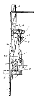
The present invention relates to a locking device for doors, intended for
connection between
the dead-bolt (1) of the door and the drive means (2) of the lock. The
invention is characterized in
that a hinged arm (6) is connected to the dead-bolt (1) or its extension (5),
a wheel (7) or pin being
arranged at the other end of the arm (6) and designed to tumble into a recess
(8) in a pivotable
cam-disc (9), or to be disengaged from this recess by means of a link
mechanism (11), whereupon
in the latter position the cam-disc (9) is arranged to block the dead-bolt (1)
in the first position
and upon tumbling into the recess (8) to release it, and also that the dead-
bolt (1) has an inclined
surface (3) designed, upon pressure against the dead-bolt, to assist in the
opening process.


French Abstract

L'invention concerne un dispositif de verrouillage de portes conçu pour assurer la liaison entre le pêne dormant (1) de la porte et le moyen de commande (2) du verrou. Elle se caractérise en ce qu'un bras articulé (6) est relié au pêne dormant (1) ou à son extension (5), une roue ou une broche prévue à l'autre extrémité du bras (6) étant conçue pour culbuter dans un évidement (8) situé dans un disque à cames (9) pivotant ou pour être délogée de cet évidement par un mécanisme de liaison (11), le disque à cames (9) étant conçu, dans cette dernière position, pour bloquer le pêne dormant (1) dans la première position et le débloquer lorsqu'il culbute dans l'évidement (8), et en ce que le pêne dormant présente une surface inclinée (3) conçue, lorsqu'une pression est exercée sur ledit pêne dormant, pour faciliter le processus d'ouverture.

Claims

Note: Claims are shown in the official language in which they were submitted.


CLAIMS

1. A locking device for doors comprising:
a dead-bolt provided with an inclined surface arranged to be influenced by
pressure, being connected to drive means of the lock;
a hinged arm having one end pivotally connected to an extension of the dead-
bolt;
a wheel/pin being arranged at an other end of the hinged arm and designed to
tumble into a recess in a pivotable cam-disc upon pivoting of the cam-disc,
which
occurs when the dead-bolt is pushed in, and also to be disengageable from this
recess by means of a link mechanism; and
whereupon the cam-disc in the latter case is arranged to block the dead-bolt
and,
upon tumbling into the recess of the wheel/pin, release it, the dead-bolt upon
pressure assisting in the opening process.
2. The locking device as claimed in claim 1, characterized in that the
inclined surface in
the dead-bolt is arranged to be influenced by pressure from one among a group
consisting of a door frame in double doors and a rotating cam.
3. The locking device as claimed in any one of claims 1 and 2, characterized
in that the
cam-disc is arranged to be turned either with or against a force exerted by a
spring.
4. The locking device as claimed in any one of claims 1 to 3, characterized in
that the
cam-disc is provided with a blocking protrusion, designed to cooperate with a
locking surface in the extension of the dead-bolt in a locking position.
5. The locking device as claimed in any one of claims 1 to 4, characterized in
that the
link mechanism comprises a link arm connected at one end to the hinged arm
between its end pivotably connected to the extension of the dead-bolt and the
wheel/pin; the link arm having an opposite end connected to a swivel plate,
the
swivel plate being operatively connected to the drive means.
6. A door lock device comprising:
5


a dead-bolt having an extension with a blocking surface;
a hinged arm having one end connected to the dead-bolt extension;
a wheel/pin arranged at the other end of said hinged arm;
a cam-disc including a recess and a locking surface; and
pivoting means for pivoting the cam-disc into a first position where the dead-
bolt
is operative in a door opening position and said wheel/pin is tumbled into the
cam-disc recess; said pivoting means being capable of moving said wheel/pin
out
of the recess so that said cam-disc be pivoted into a second position where
said
dead-bolt is maintained in a locked position.
7. The device according to claim 6, wherein said pivoting means includes a
link arm, a
swivel plate, a spring and a spring bolt, the spring bolt cooperating with the
swivel
plate and the link arm when the spring bolt is actuated against the force of
the spring
to cause the locked position.
8. The device according to claim 7, wherein the spring bolt is released and
the force of
the spring moves the swivel plate, the link arm, the hinged arm and thus
allowing the
dead-bolt into the door opening position.
9. The device according to any one of claims 6 to 8, wherein the locking
surface of the
cam-disc is positioned against the blocking surface of the dead-bolt so as to
hold the
dead-bolt in the locking position.
10. The device according to claim 8, wherein the dead bolt has an inclined
surface which
aids in opening of a locked door when the pivoting means are moved to the
second
position.
11. A locking device for a door comprising:
a dead-bolt having an extension with a blocking surface;
a hinged arm having a first end connected to the dead-bolt extension and a
wheel/pin arranged at a second end of the hinged arm;
6


a pivotable cam-disc including a recess and a locking surface;
the wheel/pin being arranged to tumble into the recess upon turning of the cam-

disc so that the dead-bolt is held in an open position;
a spring bolt;
a link mechanism actuatable by the spring bolt, said link mechanism moving the
wheel/pin out of the recess and along a surface of the cam-disc, the cam-disc
locking surface being engaged with the blocking surface of the dead-bolt
extension, thereby holding the dead bolt in a locked position.
12. The locking device according to claim 11, wherein the link mechanism
includes a
swivel plate, a link arm having one end connected to the swivel plate, the
other end
being connected to the hinged arm and a spring being arranged so that the cam-
disc is
moved either with or against the force of the spring.
7

Description

Note: Descriptions are shown in the official language in which they were submitted.


CA 02213208 2005-02-14
LOCKING DEVICE FOR DOORS
Field of the invention
The present invention relates to a locking device for doors, intended for
connection
between the dead-bolt of the door and its drive means (door-frame or rotating
cam, such
S as an electrical strike plate).
Background of the invention
It is important in different locking constructions that the lock has distinct
positions,
locked and unlocked. There is a risk when unlocking a door, for instance
during
emergency evacuation of premises, that a door cannot be opened although it has
been
unlocked in the normal manner. In critical situations this may have disastrous
results.
Both security and fire-protection aspects must be respected. The locked
position shall be
firm and unlocking shall not be made more difficult, for instance when a crowd
of people
are pushing towards the exit, thereby unintentionally preventing its opening.
Summary of the invention
The object of the invention is a solution of these and other similar problems.
One aspect of the invention provides a locking device for doors comprising: a
dead-bolt
provided with an inclined surface arranged to be influenced by pressure, being
connected
to drive means of the lock; a hinged arm having one end pivotally connected to
an
extension of the dead-bolt; a wheel/pin being arranged at an other end of the
hinged arm
and designed to tumble into a recess in a pivotable cam-disc upon pivoting of
the cam-
disc, which occurs when the dead-bolt is pushed in, and also to be
disengageable from
this recess by means of a link mechanism; and whereupon the cam-disc in the
latter case
is arranged to block the dead-bolt and, upon tumbling into the recess of the
wheel/pin
release it, the dead-bolt upon pressure assisting in the opening process.
One other aspect of the invention provides a door lock device comprising: a
dead-bolt
having an extension with a blocking surface; a hinged arm having one end
connected to
the dead-bolt extension; a wheel/pin arranged at the other end of the hinged
arm; a cam-
disc including a recess and a locking surface; and pivoting means for pivoting
the cam-
disc into a first position where the dead-bolt is operative in a door opening
position and
1

CA 02213208 2005-02-14
the wheel/pin is tumbled into the cam-disc recess; the pivoting means being
capable of
moving the wheel/pin out of the recess so that the cam-disc is pivoted into a
second
position where the dead-bolt is maintained in a locked position.
One other aspect of the invention provides a locking device for a door
comprising: a
dead-bolt having an extension with a blocking surface; a hinged arm having a
first end
connected to the dead-bolt extension and a wheel/pin arranged at a second end
of the
hinged arm; a pivotable cam-disc including a recess and a locking surface; the
wheel/pin
being arranged to tumble into the recess upon turning of the cam-disc so that
the dead-
bolt is held in an open position; a spring bolt; a link mechanism actuatable
by the spring
bolt, the link mechanism moving the wheel/pin out of the recess and along a
surface of
the cam-disc, the cam-disc locking surface being engaged with the blocking
surface of
the dead-bolt extension, thereby holding the dead bolt in a locked position.
Still another aspect of the invention is characterized in that a hinged arm is
connected to
a dead-bolt or its extension, a wheel or pin being arranged at the other end
of the arm and
designed to tumble into a recess in a pivotable cam-disc upon turning of the
cam-disc,
and also to be disengageable from this recess, whereupon the cam-disc in the
latter case
is arranged to block the dead-bolt and upon tumbling into the recess release
it, and also
that the dead-bolt has an inclined surface designed, upon pressure against the
dead bolt to
assist in the opening process. The arrangement of dead-bolt and drive means
normally
provides reliable locking and unlocking and the inclined surface assists in
ensuring
opening even in emergency situations arising out of pressure against the door
and thus
against the dead-bolt, since a force component is obtained in opening
direction of the
dead-bolt.
The invention can be used on double doors by applying it on the passive door,
where
pressure is obtained from a door-frame. The drive means comprises a spring
bolt
actuated by a door-frame.
The invention can also be applied on a single door, such as a fire-door, where
the
pressure is obtained from a rotating cam, e.g. an electrical strike plate. An
example of a
lock for a single door where the invention can be applied, is shown in Swedish
patent
2

CA 02213208 2005-02-14
application No. 8900988 or US Patent No. 5,195,792. The drive means is in this
patent
an electro-magnet, and the pressure is obtained from a rotating cam.
In a preferred embodiment the cam-disc is arranged to be turned either with or
against
spring force and the cam-disc is provided with a blocking protrusion, designed
to
cooperate in the locking position with a locking surface in the extension of
the dead-bolt.
Brief description of the drawings:
The invention will be described in more detail by way of example in the
accompanying
drawings in which:
Fig. 1 is a side elevation view of the locking device, in accordance with a
preferred
embodiment of the invention;
Fig. 2 is a front elevation view of the locking device of the present
invention; and
Fig. 3 is a top plan view, fragmented, of the locking device of the present
invention,
showing more particularly the spring bolt.
Description of the preferred embodiment
Figs 1 and 2 show the lock seen from two different directions, and Figure 3
shows a
detailed view of the spring bolt.
In Figs 1 and 2 a lock is shown having a dead-bolt (1) designed for engagement
in a
door-frame and to lock the passive door, in the case of double doors, to a
door-frame.
The dead-bolt (1) is shaped with an inclined surface (3) designed so that upon
pressure
against the door, a force component in the opening direction is produced. The
dead-bolt
has an extension (5) to which an arm (6) is hinged. A wheel (7) or pin
(wheel/pin) for
engagement in a recess (8) in a swivel cam-disc (9) is arranged at the outer
end of the
arm (6). This is the open position. To achieve locking, this wheel/pin (7) is
moved out of
the recess and up along the outer edge of the cam-disc so that the cam-disc is
pushed
inwards and a blocking surface (13) cooperates with a locking surface in the
extension
(14) of the dead-bolt. This is the locked position. The hinged arm (6) on
which the
wheel/pin is located, is connected to one end of a link arm (11), the other
end of the link
arm is connected to a swivel plate (10) which can be actuated by a spring bolt
(2). If the
3

CA 02213208 2005-02-14
spring bolt (2) is pushed out, the hinged arm (6) with the wheel/pin (7) is
actuated so that
the wheel/pin tumbles into the recess and the cam-disc swings out under the
influence
the force of a spring (12). This causes the blocking surface (13) to be
released and the
lock opens, partly due to influence from the inclined surface (3) which
receives pressure
from the door-frame. The cam-disc is moved either against or with the force of
the spring
(12). (4) denotes attachment means for the various link mechanisms. Fig. 3
shows a side
view of the spring bolt which constitutes the drive means of this lock.
The device according to the invention can be varied in many ways within the
scope of
the following claims.
4

Representative Drawing
A single figure which represents the drawing illustrating the invention.
Administrative Status

For a clearer understanding of the status of the application/patent presented on this page, the site Disclaimer , as well as the definitions for Patent , Administrative Status , Maintenance Fee  and Payment History  should be consulted.

Administrative Status

Title Date
Forecasted Issue Date 2006-04-18
(86) PCT Filing Date 1996-02-12
(87) PCT Publication Date 1996-08-22
(85) National Entry 1997-08-15
Examination Requested 2003-02-11
(45) Issued 2006-04-18
Deemed Expired 2016-02-12

Abandonment History

There is no abandonment history.

Payment History

Fee Type Anniversary Year Due Date Amount Paid Paid Date
Application Fee $150.00 1997-08-15
Maintenance Fee - Application - New Act 2 1998-02-12 $50.00 1997-08-15
Registration of a document - section 124 $100.00 1997-12-02
Maintenance Fee - Application - New Act 3 1999-02-12 $50.00 1999-02-10
Maintenance Fee - Application - New Act 4 2000-02-14 $50.00 2000-02-08
Maintenance Fee - Application - New Act 5 2001-02-12 $75.00 2001-01-16
Maintenance Fee - Application - New Act 6 2002-02-12 $75.00 2002-02-12
Maintenance Fee - Application - New Act 7 2003-02-12 $75.00 2003-01-20
Request for Examination $200.00 2003-02-11
Maintenance Fee - Application - New Act 8 2004-02-12 $100.00 2004-02-12
Maintenance Fee - Application - New Act 9 2005-02-14 $100.00 2005-01-12
Final Fee $150.00 2005-11-30
Maintenance Fee - Application - New Act 10 2006-02-13 $125.00 2006-01-27
Expired 2019 - Corrective payment/Section 78.6 $1,200.00 2007-01-23
Maintenance Fee - Patent - New Act 11 2007-02-12 $250.00 2007-01-31
Maintenance Fee - Patent - New Act 12 2008-02-12 $250.00 2008-01-30
Maintenance Fee - Patent - New Act 13 2009-02-12 $250.00 2009-02-05
Maintenance Fee - Patent - New Act 14 2010-02-12 $250.00 2010-02-01
Maintenance Fee - Patent - New Act 15 2011-02-14 $450.00 2011-01-28
Maintenance Fee - Patent - New Act 16 2012-02-13 $450.00 2012-01-16
Maintenance Fee - Patent - New Act 17 2013-02-12 $450.00 2013-02-07
Maintenance Fee - Patent - New Act 18 2014-02-12 $450.00 2014-01-23
Owners on Record

Note: Records showing the ownership history in alphabetical order.

Current Owners on Record
STENDALS ELEKTRISKA AB
Past Owners on Record
STENDAL, JAN
Past Owners that do not appear in the "Owners on Record" listing will appear in other documentation within the application.
Documents

To view selected files, please enter reCAPTCHA code :


To view images, click a link in the Document Description column. To download the documents, select one or more checkboxes in the first column and then click the "Download Selected in PDF format (Zip Archive)" or the "Download Selected as Single PDF" button.

List of published and non-published patent-specific documents on the CPD .

If you have any difficulty accessing content, you can call the Client Service Centre at 1-866-997-1936 or send them an e-mail at CIPO Client Service Centre.


Document
Description 
Date
(yyyy-mm-dd) 
Number of pages   Size of Image (KB) 
Representative Drawing 1997-11-14 1 4
Description 2005-02-14 4 165
Claims 2005-02-14 3 99
Drawings 2005-02-14 1 17
Cover Page 1997-11-14 1 46
Abstract 1997-08-15 1 43
Description 1997-08-15 3 115
Claims 1997-08-15 2 50
Drawings 1997-08-15 1 16
Representative Drawing 2006-03-21 1 6
Cover Page 2006-03-21 1 39
Assignment 1997-08-15 5 191
PCT 1997-08-15 9 341
Correspondence 1997-10-28 1 32
Assignment 1997-12-02 3 84
Prosecution-Amendment 2003-02-11 1 40
Prosecution-Amendment 2004-08-12 2 69
Prosecution-Amendment 2005-02-14 11 360
Correspondence 2005-11-30 1 40
Correspondence 2007-02-13 1 20
Prosecution-Amendment 2007-01-23 2 54
Fees 2007-01-23 2 59
Prosecution-Amendment 2007-02-26 1 25
Prosecution-Amendment 2007-06-05 1 11
Prosecution-Amendment 2007-06-08 4 105