Note: Descriptions are shown in the official language in which they were submitted.
CA 02231802 1998-04-15
1
AN AERATED CUSHIONING STRUCTURE WITH A VARIABLE
DENSITY THROUGHOUT
FIELD OF THE INVENTION
The present invention relates to a cushioning
structure suitable for use as a shoe sole or insole but
also as an insert structure for cushioning any obj ect
thal~ requires cushioning properties such as a seat
COVe ring, a bicycle seat or a mattress. More
part=icularly, it relates to a single flexible structure
including an aeration system and a variable density
throughout specifically selected according to the
variable pressure points of the structure.
BACKGROUND OF THE INVENTION
Commonly use in prior art for cushioning a car
se at, a chair, a mattress or any other object that
requires cushioning properties, there is the traditional
foam pad which consist of a uniform thickness pad having
a uniform density throughout absent of any particular
aeration system.
The prior art also teaches a number of structures
used as shoe soles and consisting of a single layer of
flee>ible material incorporating a plurality of asperity
dist=ributed thereon and acting as individual suspension.
Examples of such prior art shoe soles are given in U.S.
Pat.. No. 4,345,387; 4,541,185; 4,733,483; 4,831,749 and
4, 896, 441 .
Also disclosed in prior art, there are different
types of soles incorporating pumping means for aerating
the foot during the walking movement of the user.
Examples of such prior art shoe soles are given in U.S.
CA 02231802 1998-04-15
2
Pat. No. 4,215,492; 4,224,746; 4,468,869; 4,813,160;
4, 831, 749 and 5, 619, 809.
There are also a number of orthopaedic innersoles
disclosed in prior art which provide an adequate
con:Eormation to the particular shape of the bottom of
the foot in order for example to correct eventual
defects to the user's foot. Such innersoles are
disclosed in U.S. Pat. No. 4,345,387; 4,598,484;
4, 733, 483 and 4, 896, 441 .
The following documents are other examples of prior
art shoe soles: U.S. Pat. No. 4,223,455; 4,224,746;
4,468,869 and 4,776,109.
Although many developments have been made,
espE=_cially in the shoe industry, for providing
com:Eortable soles, there is still a need for a simple
universal cushioning structure that could provide in the
same time a real comfort adapted to the physical
cha~_acteristics of t:he user and an efficient aeration
system. There is also a need for that type of structure
for cushioning any object that requires cushioning
properties such as a seat covering, a bicycle seat, a
shoe sole or a mattress.
SUMMARY OF THE INVENTION
An object of the present invention is to provide a
cushioning structure that satisfies the above-mentioned
needs.
In accordance with the present invention, that
object is achieved with a cushioning structure
comprising a single central layer made of a flexible
material and having' an upper surface and a bottom
surface each provided with a plurality of comfort pins
integral with the central layer. Those comfort pins have
variable shapes, sizes and height to thereby vary the
' CA 02231802 1998-04-15
3
density of the cushioning structure throughout. The
shape, size and height of the comfort pins are
determined according to the specific pressure points of
the structure in use. The central layer also comprises
a plurality of air holes distributed between the comfort
pins. Each air hole extends across the central layer
frorn the upper surface to the bottom surface.
A non restrictive description of preferred
embodiments will now be given with reference to the
appended drawings.
BRIEF DESCRIPTION OF THE DRAWINGS
FIG. 1 is a bottom view of a preferred embodiment
of a cushioning structure according to the present
invention used as a shoe sole;
FIG. 2 is a cross-sectional side view of the
cushioning structure shown in FIG. 1 taken along line A
2 0 A; and
FIG. 3 is a cross-sectional side view of the
cushioning structure shown in FIG. 1 taken along line B-
B.
CA 02231802 1998-04-15
4
DESCRIPTION OF A PREFERRED EMBODIMENT
The cushioning structure according to the invention
is intended to be used as an insert structure for
cushioning any object that requires cushioning
properties such as a shoe sole or insole, a seat
covering, a bicycle seat or a mattress.
This cushioning structure is preferably thin and
comprises a central 7_ayer of flexible material having a
regular or a variable thickness. This layer comprises an
upper surface and a bottom surface each provided with a
plurality of comfort pins made of a flexible material.
These comfort pins may have variable shapes (cubic,
spheric, cylindric, ...), size, height and distribution
over the central layer, t:o thereby vary the density of
the cushioning structure throughout. The central layer
also comprises a plurality of air holes distributed
between the comfort pins. Each air hole extends across
the central layer from the upper surface to the bottom
surface.
The comfort pins may be made of the same material
as the central layer, or of a different material.
Preferably, the central layer and the comfort pins are
made of natural or synthetic rubber. The layer and the
pins can be full, hollow, or filled with a material
different from natural or synthetic rubber such as foam
or gel.
As stated previously, the shape, size, height and
composition of the comfort pins may vary and the choice
of these characteristics .is determined according to the
specific pressure points and the density required at
' CA 02231802 1998-04-15
specific locations of the structure in use. Of course,
the thickness of the central layer can also be adjusted.
By f=xample, if the cushioning structure is used in the
fabrication of a bicycle seat, the density may be
5 adjusted for providing an ergonomic and comfortable
seat. Such cushioning structure could also be used as a
shoe sole, the central layer and comfort pins having a
variable thickness providing an orthopaedic profile for
the shoe sole (see Figures 1 to 3).
The accompanying drawings illustrate one preferred
embodiment of the invention. In that case, the use of
the cushioning structure is a shoe sole or insole.
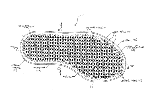
Referring to Figures 1 to 3, this insole (1) is
preferably thin and comprises a central layer (10) of
flexible material having a regular thickness. This layer
(10) comprises an upper surface (14) and a bottom
surface (12). In this preferred embodiment, the central
layer (10) further comprises on it's bottom surface (12)
an outline frame (11) shaped like a foot.
The upper surface (14) comprises a plurality of
small buttons (21) projeci~ing upwardly from the central
layer (10). These small buttons (21) can produce a
massage effect to the user. The bottom surface (12) is
provided with a plurality of comfort pins (20) extending
dowr~wardly from the central layer (10). The buttons (21)
and the comfort pins (20) are preferably made of a
flexible material and may have variable shapes (cubic,
spheric, cylindric, ...), size, height and distribution
over_ the central layer, depending on the density and
support required at specific locations of the insole. By
example, in the illustrated preferred embodiment, the
insole (1) comprises comfort pins (20) which are longer
CA 02231802 1998-04-15
6
in order to define the area under the arch of the foot
( 32 ) and under the toe grip ( 34 ) . The same insole ( 1 )
also comprises comfort pins (20) which are shorter in
order to define the area under the heel (36)(Figures 2
and 3). The variation in the characteristics of the
central layer (10), comfort pins (20) and buttons (21)
thus permit to provide an orthopaedic profile adapted
for an insole.
The comfort pins (20) may be made of the same
material as the central layer (10), or of a different
material. Preferably, the central layer (10) and the
comfort pins (20) are made of natural or synthetic
rubber . The layer ( 10 ) and the pins ( 2 0 ) can be ful l,
hollow, or filled with a material different from natural
or synthetic rubber such as foam or gel.
To promote air circulation over the upper surface
(14) of the insole (1) and also between the upper (14)
and bottom surface (12) of the central layer (10), the
central layer (10) also comprises a plurality of air
holes (18) distributed between the comfort pins (20) and
the buttons (21). Each air hole (18) extends across the
central layer ( 10 ) from the upper surface ( 14 ) to the
bottom surface (12). Thanks to the combination of
comfort pins (20), the buttons (21) and the air holes
(18), the insole (1) acts as an aerated air cushion.
When a pressure is applied on the insole ( 1 ) , the air
between the pins (20) is expelled through the air holes
(18). When the pressure is removed, the air returns back
through these air holes (18) thereby allowing the insole
(1) to be aerated. Although the holes (18) illustrated
in this preferred embodiment are the same size and are
distributed evenly over t:he surface of the insole (1),
CA 02231802 1998-04-15
7
it should be understood that these holes (18) may also
be distributed unevenly and be different in their size.
Although preferred embodiments of the invention
have been described in detail herein and illustrated in
the accompanying drawings, it is to be understood that
the invention is not limited to these precise
embodiments and that various changes and modifications
may be effected therein wii~hout departing from the scope
or spirit of the invention.