Note: Descriptions are shown in the official language in which they were submitted.
CA 02232755 2000-06-27
EMPLOYING CUSTOMER PREMISES EQUIPMENT
IN COMMUNICATIONS NETWORK MAINTENANCE
Field Of The Invention
The present invention is directed to a method and system for employing
customer premises equipment (CPE) as an agent in communication network
maintenance; and, in a particular embodiment, for employing CPE to aid in
measuring the effect of network loss on received sound quality so that such
loss may be compensated and sound quality thereby improved.
Background Of The Invention
TrueVoice~ is a telephone network sound enhancement technology
invented by AT&T Corp. TrueVoice provides AT&T customers with "closer,"
clearer sounding voice communications on telephone calls carried by the
AT&T network. TrueVoice applies both a frequency independent gain (a
constant gain across all frequencies in the telephone bandwidth) and a
frequency selective gain (sometimes referred to as "pre-emphasis") to
telephone connections. Technical features of TrueVoice are described in
United States Patents Nos. 5,195,132; 5,333,195; and 5,206,902.
Figure 1 is a diagram of a typical telephone network connection
employing TrueVoice. It includes CPE 20 and 21 at two end points for a
calling party and a called party, respectively, and analog and digital network
components in between. CPE 20, 21 is, e.g., a conventional telephone. CPE
20, 21 is connected to a conventional hybrid converter 22, 23 at telephone
central offices via local loops 31, 34. Each hybrid 22, 23 converts bi-
directional signal transmission in a two-wire telephone line to two
unidirectional signal paths (two wires each). The calling party's "transmit
path" includes local loop
CA 02232755 2000-06-27
2
31, network paths 35 and 36 and local loop 34. This transmit path is also the
called party's "receive path." The called party's transmit path includes local
loop 34, network paths 38 and 37, and local loop 31. This transmit path is
also
the calling party's receive path. (Local loops 31 and 34 are common to both
calling and called parties' transmit and receive paths.) The point of the
network
between paths 35 and 36 / 37 and 38 is said to be at 0 "TLP" (or transmission
level point). This point may be conveniently used as a reference for gain or
loss experienced at different points in the network.
Signals on the calling party transmit network path 35 are processed by a
D/A-A/D converter 24, which is conventional equipment located at the calling
party's local central office. (For clarity of presentation of the invention,
conventional switches associated with the local central offices are not
shown.)
A long-distance telephone network switch, e.g., a No. 4 Electronic Switching
System 26 (4ESS) in the AT&T Network, is connected to the D/A-A!D 24
converter of the local central office. The 4ESS 26 is then connected to a
special automatic volume control filter (AVC) 30 which, as shown in Figure 1,
includes, for example, TrueVoice~ elements 32 and 33. As a matter of general
background, automatic volume control filters are conventional, for example,
those described in 4,499,578 and 4,535,445. TrueVoice element 33 applies the
sound enhancement for speech signals spoken at CPE 20 for transmission to
CPE 21. Element 32 applies echo cancellation to diminish an echo of speech
signals (originally spoken at CPE 21) returning to CPE 21. As shown in Figure
1, similar connections are used in network path 36 to deliver speech from the
calling party. This path includes a -6 dB attenuator 29, intentionally
inserted
into the network, typically by the called party's Local Exchange Carrier
(LEC),
to further mitigate echo in a long distance connection (it is not needed in a
local connection). The Figure further illustrates similar connections for
network path 38 (which is like network
CA 02232755 1998-03-19
3
path 35) and network path 37 (which is like network path 36). (Although much
of the discussion which follows is presented from the point of view of the
calling
party's transmit path (which is the same as the called party's receive path),
such discussion has applicability to the called party's transmit path /
calling
party's receive path, with for example, the roles of elements 32 and 33
reversed.)
The part of the network which is digital - that part between and including
D/A-A/D converters 24, 25 - exhibits no unintentional loss (there are -6 dB
attenuators 28, 29, however, which are intentionally placed in the circuit).
The
analog part of the network - the balance of the network diagram of Figure 1 -
does suffer unintentional loss, however. This loss is variable depending on
the
length of the local loop 31, 34 between the CPE 20, 21 and the central office.
In addition, the level of a speech signal presented to the analog part of the
network is variable, depending on the CPE (telephone) 20, 21 microphone
efficiency, as well as how loudly a person is speaking into the microphone and
how close the person's mouth is to the microphone. As shown in the Figure,
the average loss on the analog portion of the calling party's transmit path -
referred to as TOLR (telephone + local loop loss) is -46 dB.
As discussed in greater detail in the referenced patents, TrueVoice~ 33
sound enhancement operates to mitigate the effect of signal loss in a
telephone
network connection for signals traveling from the calling party to the called
party. TrueVoice 33 sits in the middle of the digital network and adds gain of
a
fixed amount (4 dB) to a computed input power of a transmitted speech signal.
Figure 2 illustrates this. The power of the transmitted (input) signal is
computed
over a time interval. For example, the signal may have an average power over
the interval of -21 dB. TrueVoice will amplify the signal such that the signal
will
have an average power of 4 dB better (or -17 dB). If the average power of the
input signal is -17 dB, the output power will be raised to -14 dB. Through its
CA 02232755 1998-03-19
4
combination of pre-emphasis (base boost) and the AVC, TrueVoice 33
compensates some or all of the network path 31, 35 attenuation, as well as
CPE 20 efficiency variation, to improve how speech carried over the telephone
connection "sounds" to someone listening.
Although there is an optimal TrueVoice 33 output power level to which
the network signal could be adjusted, TrueVoice employs a conservative boost
of, e.g., a constant 4 dB, to compensate for attenuation suffered in the paths
31 and 35 of the network. Unfortunately, there are several variables related
to
the paths 34 and 36 of the network which affect the amount of signal loss a
speech signal may suffer in transmission over a telephone circuit. For
example, the attenuator 29 is not always present in a long distance
connection.
Network response variability is also caused by variation in local-loop 34
length
carrying received signals and variability in the efficiency of CPE 21's
electric-to-
acoustic transduction. This response variability can cause, among other
things,
variability of objective loudness as perceived by telephone customers.
Moreover, because TrueVoice~ 33 applies a conservative gain mapping (4 dB,
for example) when administering active volume control, called parties
connected on long loops or loops that cause great attenuation may not be able
to perceive all the benefits of TrueVoice~ 33. Since TrueVoice 33 does not
know what the loss will be on the paths 36, 34 of the network, it does not
compensate for such loss and, in fact, provides a relatively conservative
maximum gain because of this.
Summary Of The Invention
The present invention is directed to the use of CPE as an agent of the
network to assist in providing network maintenance. An illustrative embodiment
of the invention is directed to improving network sound enhancement systems,
such as TrueVoice. In this embodiment, the TrueVoice network element 41
CA 02232755 1998-03-19
(see Figure 3) emits a first signal at the beginning of an ordinary telephone
call
(where the reference numeral 41 has been used, rather than numeral 33, to
indicate a TrueVoice element employing features related to an embodiment of
the invention). This first signal is illustratively a sub-audible 25 Hz tone
referred
5 to as a "tag" signal (which the network otherwise uses with conventional
TrueVoice to indicate to other network components that TrueVoice is being
applied; see U.S. Patent No. 5,206,902). When the CPE senses the first
signal, it measures the loss in the signal (knowing a priori at what level the
signal was transmitted) and responds with a signal of its own -- a calibration
signal. This calibration signal represents a measure of the first signal loss
sensed by the CPE on the call. Illustratively, the calibration signal has the
loss
value encoded therein. The TrueVoice network 41 element decodes the
measured loss information and adjusts the transmitted telephone signal (which
is sent to the CPE 42) to account for the measured loss. In this embodiment,
the system assumes that the loss measured at 25 Hz is applicable at other
audible frequencies. Because signal loss is measured, network sound
enhancement can be tailored on a call-by-call basis.
Embodiments of the present invention may also employ a wide-band
signal (in addition to or instead of the tag signal) to allow measurement of
loss
at various frequencies in the audible range. The coded calibration signal then
represents loss at these various frequencies. TrueVoice network element 41
adjusts the transmitted signal level differently at different frequencies so
as to
obtain a more frequency-dependent enhancement to network sound. The
calibration signal may be of any suitable type and may include DTMF signals,
coded sub-audible signals, spread spectrum signals, data signals from a voice-
over-data modem signals, etc.
A further alternative embodiment is one in which the CPE does not
measure the first signal, but merely provides a "loop back" of such signal to
the
CA 02232755 2000-06-27
6
network. The loop back signal level is then measured by the TrueVoice
network element and loss is then estimated. In this embodiment, the loss
measured by the network includes loss suffered in both a receive and transmit
path (during both the transmission of the first signal, as well as the loop
back
transmission from the CPE). Therefore, loss in just the receive path must be
estimated as, for example half of the total loss measured by the network
element.
In these embodiments, the CPE is participating in the maintenance of
the telephone network - in this case, the maintenance of network sound
quality. This maintenance behavior shifts the paradigm of the "intelligent
network but'dumb' terminal" (CPE) to one which employs "smart" CPE
providing assistance to the network in performing network maintenance.
In accordance with one aspect of the present invention there is provided
a method for enhancing performance of a telephone network, the method
comprising: transmitting a first signal from a telephone network element to
customer premises equipment (CPE) via a telephone network path; receiving
from the CPE a second signal representing loss experienced by the first signal
due to transmission via the path; and adjusting gain applied to a speech
signal
transmitted from the network element to the CPE based on the second signal.
Brief Description Of The Drawings
Figure 1 is a diagram of a basic network connection.
Figure 2 is a graph of a prior art gain map for active volume control in
the basic network connection shown in Figure 1.
Figure 3 is a diagram of an illustrative network connection according to
the present invention.
Figure 4 is a diagram of the operation of the network connection in
Figure 3.
Figure 5 is an illustrative gain map for a TrueVoice system that
CA 02232755 2000-06-27
6a
assumes a prototypical loss between TrueVoice system and the listener at
CPE, in accordance with the present invention.
Detailed Description
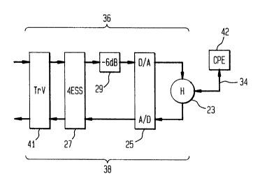
The present invention will now be described in accordance with an
illustrative embodiment presented in Figure 3. Figure 3 depicts a called
party's
half of a telephone network connection. The system depicted includes an
CA 02232755 1998-03-19
7
enhanced TrueVoice system 41, network attenuation element 29, a D/A-A/D
converter 25, a hybrid converter 23, and CPE 42. System 41 comprises
conventional digital signal processing hardware and software for performing
the
functions described below. As discussed above with reference to Figure 1,
Figure 3 includes portions of called party receive and transmit paths 36, 38,
respectively.
Gain Mapping
The illustrative embodiment of Figure 3 functions to adjust the overall
level of the signal transmitted to the called party. Steps carried out by the
salient elements of Figure 3 are illustrated in Figure 4. The TrueVoice
network
signal processor 41 emits a tag signal, for example, a 25 Hz tone (which is
also
provided by conventional TrueVoice~ 33), on the called party's receive path 36
to the CPE 42. Step 50. CPE 42, using conventional signal processing
techniques, detects the presence and level of the tag signal. Step 52. The
paper "Algorithms for Multi-Channel DTMF Detection for the WEDSP32
Family," Gay et. al., Proc. IEEE International Conf. on Acoustics, Speech and
Sig. Pro., pp. 1134-1137, 1989, sets forth illustrative signal processing
techniques for detecting tones in the subscriber loop (and is hereby
incorporated by reference as if set forth fully herein). The CPE 42 may
provide
a visual indication notifying a customer that TrueVoice 41 is present through
use of a lamp, LED, LCD display or other icon. The network enhancement
(TrueVoice~) can also be audibly branded by, for example, using a unique tone
or announcement.
In response to detecting the 25 Hz tag, CPE 42 issues a first calibration
signal. Step 53. The first calibration signal can be, for example, a tone,
white
noise, a spread spectrum signal, etc. This calibration signal represents the
amount of loss suffered by the tag in traversing the receive path 36, 34 to
the
CA 02232755 1998-03-19
8
CPE 42 from the TrueVoice processor 41. First, CPE 42 computes the
received tag signal power using any of the conventional techniques. For
example, a measure of signal power may be computed as the square of the
received signal voltage. Then, the loss is determined as the difference
between
received tag signal power and transmitted tag signal power (known a priors).
CPE 42 then encodes the measured loss using any of the available techniques.
For example, loss can be represented as a number of tone bursts, a duration
of a tone, or data transmitted as a spread spectrum signal.
Detection of the 25 Hz tag can be in the analog domain to avoid
problems incurred in signal conversion. This would allow detection for a
broader class of CPE that may not have digital signal processing capability.
However, tag detection, loss computation, and calibration signal generation
can
be readily performed with conventional techniques by CPE 42 (e.g.,
telephones) having signal processing capabilities.
The TrueVoice system 41 receives the calibration signal transmitted by
CPE 42 via path 38 and decodes the loss value represented by the signal using
a conventional detection process suitable to the encoding of the calibration
signal (such as counting tone bursts, measuring tone length, or receiving and
decoding a spread spectrum signal). Step 54. As a result of having this
measure of loss in the called party's receive path 36, 34, the TrueVoice
system
41 adjusts the gain on the signal it transmits on that path 36 to compensate
for
the measured signal loss. Step 56.
While loss is what is most likely, it may be that the local loop 34 of the
called party actually provides a gain. In such a case, the TrueVoice system 41
can scale back its gain to avoid overwhelming the called party. On a long or
weak local loop 34, a more aggressive gain can be applied to compensate for
loss. Because of this, the term "loss" can be generally construed in either
its
positive sense - signal level attenuation - or its negative sense - signal
boost -
CA 02232755 1998-03-19
9
experienced during transmission of the tag signal on the path 36, 34.
Similarly,
the term "gain" can be generally construed in either its positive sense -
signal
boost - or in its negative sense - signal attenuation. For purposes of
embodiment illustration, however, the terms "loss" and "gain" are used in
their
positive senses. Naturally, the inventive concepts go to either senses of
these
terms.
TrueVoice system 41 operates in accordance with a two stage process
to apply appropriate gain in accordance with the invention. First, the input
signal to element 41 on path 36 is processed in accordance with a gain map.
The gain map provides a signal gain, over a range of input power, that
appropriately compensates for variations in signal power introduced prior to
that
point in the connection (i.e., by elements 20, 31, and 35, see Figure 1) and
that
assumes a prototypical loss characteristic for the remainder of the circuit
(i.e.,
for elements 36, 34, and 42). This gain would be applied in accordance with
the gain map regardless of whether system 41 received any calibration signal
from CPE 42. An illustrative gain map is presented in Figure 5. If the
calibration signal is received by TrueVoice system 41, then further signal
processing is performed on the input signal to adjust it in accordance with a
level of gain (or loss) indicated by the calibration signal. That is, the
output
signal from the gain map stage (i.e., the input signal adjusted in accordance
with the gain map) is multiplied by a gain (or loss) value provided in
accordance
with the calibration signal. Thus:
So=S9m*9c
where So is the signal output from system 41, S9," is the signal from the
gain map stage of system 41, and g~is the gain determined in accordance with
the calibration signal. If no calibration signal is received (because of the
CA 02232755 1998-03-19
absence of CPE capable of participating in the calibration process, for
example), this second stage gain factor is unity (effectively providing no
adjustment beyond the gain map stage). Thus, with an appropriate gain
applied by system 41, callers on long loops receive sufficient gain to
perceive
5 the benefits of the TrueVoice~ enhancement. Further, the risk of over
driving
callers on shorter loops is eliminated.
Spectral Shaping
Spectral shaping is the process by which the level of a signal is adjusted
on a frequency-dependent basis so as to achieve a desired "sound" at the CPE
10 42. This is done by a process which determines the frequency response of
the
receive path 36, 34 and adjusts the level of the signal communicated over that
path so as to achieve a desired effect, such as a flat (i.e., equalized) over-
all
frequency response. Spectral shaping is achieved in accordance with the
illustrative embodiment of the present invention as shown in Figures 3 and 4
and may be performed instead of or in addition to the gain mapping discussed
above.
To perform spectral shaping, the TrueVoice system 41 issues a wide-
band signal to CPE 42. Step 58. This wide-band signal includes frequency
components across the band in which spectral shaping is desired. The wide-
band signal illustratively comprises sinusoids (tones) of equal amplitude
spaced
at 50 Hz intervals across the standard telephone bandwidth. The CPE 42
detects the tones and determines the loss at the tone frequencies with the use
of conventional tone detection techniques. Step 60. CPE 42 then encodes the
tone loss values and transmits a calibration signal back to the TrueVoice
system 33. Step 61. As discussed above, encoding of the measured loss of
the tones by CPE 42 can be done using any of the available techniques. For
example, loss at a tone frequency can be represented as a number of tone
bursts, a duration of a tone, or data transmitted as a spread spectrum signal.
CA 02232755 1998-03-19
11
The TrueVoice system 41 receives the calibration signal transmitted by
CPE 42 and decodes the tone loss values represented by the calibration signal
using a conventional detection process suitable to that signal (such as
counting
tone bursts, measuring tone length, or receiving and decoding a spread
spectrum signal). Step 62. The TrueVoice system 41 performs conventional
interpolation of tone loss values it determines from the received calibration
signal to approximate loss values at frequencies other than the tone
frequencies. As a result of having this measure of loss in the called party's
receive path 34, 36 at various frequencies, the TrueVoice system 41 adjusts
the gain on the signal it transmits on path 36 to compensate for the measured
signal loss. Step 64. In this case, the gain is variable with frequency, in
accordance with the calibration signals received from the CPE 42. Gain may
be applied as discussed above for each range of frequencies desired.
As an alternative to transmitting calibration signals back to the TrueVoice
system 41, whether relating to a single tone or a wideband signal, the CPE 42
can apply conventional equalization to the signals received from path 36 to
enhance the quality of sound reproduced at the CPE 42, rather than relying on
the network element to do so.
Loop Back
In both the gain mapping and spectral shaping discussions above, loss
caused by a signal's traversal of the receive path 34, 36 is measured by the
CPE and communicated back to the TrueVoice system 41 where compensation
for the measured loss is applied. However, a measure of gain mapping and/or
spectral shaping can be achieved through a "loop back" process. The loop
back process is one in which the CPE 42 does not measure and communicate
information relating to signal loss to the TrueVoice system 41, but rather the
CPE receives a tag or wide-band signal from the TrueVoice system 41 on path
CA 02232755 1998-03-19
12
36 and returns (or "loops back") the signal to the TrueVoice system 41 on
patf,
34, 38. The returned signal has thus traversed a loop from and to the
TrueVoice system 41 via the CPE 42 and any loss experienced by the signal is
the result of the signal traversing the two paths 34, 36, and 34, 38 (negating
the
effects of the CPE 42). Thus; the TrueVoice system 41 itself can determine
directly what type of gain mapping/spectral shaping to do, rather than involve
the CPE 42 in any computation of loss.
This loss as measured in accordance with the loop back technique is
caused by both paths 34, 36 and 34, 38. Consequently, the TrueVoice system
must approximate that portion of loss due to the receive path 34, 36 only.
Loss
could be apportioned evenly between the two paths, or, proportionately if a -6
dB attenuation is present in path 36.
Discussion
The present invention provides communication between the TrueVoice
system 41 and the CPE 42. This allows for a prescribed signal to be sent by
one device to the other such that the other device can estimate the effects of
the subscriber loop, i.e., signal loss, spectral shaping, etc. The embodiments
of
the present invention employ CPE as an agent of the network to assist in
providing network maintenance. In these illustrative cases, the CPE acts as an
agent to assist in the maintenance of network frequency response and volume
control. The principles of the present invention may be extended to other
situations where CPE can provide network elements with information about
network performance so that the network can adjust its operation to maintain,
e.g., service quality.
Although a number of specific embodiments of this invention have been
shown and described herein, it is to be understood that these embodiments are
merely illustrative of the many possible specific arrangements which can be
CA 02232755 1998-03-19
13
devised in application of the principles of the invention. Numerous and varied
other arrangements can be devised in accordance with these principles by
those of ordinary skill in the art without departing from the spirit and scope
of
the invention.
For example, while the first signal is described as being sub-audible
(e.g., the tag signal), an audible tone may be used.
As used herein, the term "wide-band" refers to a signal having more than
a single frequency component, as distinct from the term "tone," which refers
to
a signal having a single frequency component.
As stated above, the network enhancement (TrueVoice~) can may be
audibly branded by, for example, use of a unique tone or announcement. Such
a tone or announcement may be generated within the telephone network and
played at the CPE or it may be generated by the CPE in response to receipt of
a first signal.