Note: Descriptions are shown in the official language in which they were submitted.
CA 02243820 1998-07-23
Attorney Docket
No. 37077/53
CANADIAN
APPLICATION FOR LETTERS PATENT
INVENTOR: Melvin S. Mogil
TITLE: PACK STRUCTURE
20511449.1
CA 02243820 1998-07-23
1
PACK STRUCTURE
Field of Invention
This invention relates generally to portable packs that include a cooling
compartment. In particular it relates to a kind of portable pack that can be
used in a
number of outdoor activities, such as, for example, while golfing.
Background of the Invention
People enjoying outdoor activities often desire refreshment. In the summer the
usual desire is for something cool to drink. In the spring or fall a warm
beverage or snack
may be preferred. It may be that those persons wishing refreshment are a
considerable
distance from the nearest tea shop or refreshment stand. They may have hiked
some
distance, or, in the case of golf, have reached a point far out on the course.
In such
circumstances it is convenient to be able to take a supply of cooled or heated
refreshments
along, for use as desired.
Another related problem, particularly when golfing as a visitor, is that
secure
locker facilities may not be available. It is often uncomfortable to golf with
a wallet or set
of keys contained in one or another pants pocket. A golfer may wish to keep
his or her
valuables, such as a wallet and car keys, close at hand during a round of
golf, in a
container that is within the golfer's view. In recent times the growing
popularity of
cellular telephones has made it possible for golfers, hikers, cross country
skiers, picnickers
or others, to remain in touch with their business colleagues while enjoying
their outdoor
activities, often so smoothly that others may be scarcely aware that they are
not at the
office. A cellular telephone is another object that is uncomfortable to carry
when golfing
or skiing, for example. Cellular telephones are easily stolen and highly
marketable. For
both convenience of use and discouragement of theft they should be kept
relatively close
to the user. At the same time, the ability to carry, for example, extra golf
balls, chocolate
20507246
CA 02243820 1998-07-23
2
bars, or gum, and to carry a score card or map in a visible position, with
enhanced
accessibility are further common needs.
It may be uncomfortable, or cumbersome to having a multiplicity of objects to
carry. A number of items may fit within a golf bag, along with various clubs,
but the golf
bag may not be suil'lciently large to carry some items, and some items may
risk damage
if placed in the golf bag itself. A golf bag is not generally a convenient
place to have a
cooling medium, such as ice cubes. Further, the prospect of spilling lemonade,
carbonated
drinks, or beer, however much by accident, inside either the golf bag amongst
the woods
and irons, or in a pocket of the golf bag, is not one that would be greeted
with enthusiasm
by many golfers. A segregated auxiliary carrying case that is separately
washable, that is
mountable to the golf bag, and that can be carned with it is preferable. It
would be even
more advantageous to have a pack that can be mounted with the golf bag when
the bag
is carried on a wheeled carriage or in a golf cart. In this way a golfer's
hands are not
further encumbered.
Summar~of the Invention
In a first aspect of the invention there is a pack. It has an insulated
compartment,
an auxiliary compartment mounted next to the insulated compartment and a mount
for
attaching the pack to another object. The auxiliary compartment has a
receptacle of a size
for receiving a telephone handset, another receptacle of a size for receiving
a wallet, and
a closure securable in a closed position to conceal the contents of the
receptacles.
In an additional feature of that aspect of the invention, the pack has a
breadth
corresponding to the thickness of a golf bag. In another additional feature of
that aspect
of the invention, the pack has a second mount for inhibiting swaying of the
pack relative
to the other object. In a fi.uther additional feature of that aspect of the
invention, the pack
includes a see-through pocket mounted externally to the auxiliary compartment.
The see-
through pocket is of a size to receive a golf ball.
20507246
CA 02243820 1998-07-23
3
In another additional feature of that aspect of the invention, the pack has a
leading
panel for placement adjacent to the golf bag, a pair of side regions, a
trailing region, a
bottom and a top. A see-through pocket is mounted to one of said side regions.
The see-
through pocket has an access lip that has a leading portion and a trailing
portion. The
leading portion has a Beater attitudinal dimension relative to said pocket
than said trailing
portion.
In a further additional feature of that aspect of the invention, the pack has
a lid.
The lid has a handle. The handle has a reinforced attachment to the lid,
whereby, when
closed, the pack can be carned by the handle.
In a still further additional feature of that aspect of the invention, the
insulated
compartment has a substantially impermeable liner; and the liner can be
inverted to
facilitate washing. In yet another additional feature, the insulating
compartment has a
thermal transfer medium holder, and that holder is vented.
In still another fi~rther additional feature of that aspect of the invention,
the
auxiliary compartment includes a key holder. In a still further feature of
that additional
feature, the key holder includes a lanyard secured within said auxiliary
compartment.
In another aspect of the invention, there is an insulated pack. It has an
insulated
compartment. It has a first mount, for carrying the weight of the pack. The
first mount
is located on an upper region of the pack and is for attaching the pack to
another object.
The pack also lmse~ond mount located on a lower region of the pack for
attaching to the
other object at a different location than the first mount.
In an additional feature of this aspect of the invention, the pack is
reinforced at the
location at which the first mount is attached to it. In another additional
feature of the
invention, the pack is reinforced at the location at which the second mount is
attached to
20507246
CA 02243820 1998-07-23
4
it. In a further additional feature, the first mount is a quick release
hanging mount and the
second mount is a cinch strap.
In another additional feature of that aspect of the invention, the pack
further
comprises a soft shell wall having leading portion, a trailing portion, a pair
of side
portions, and a bottom portion. The soft shell wall has an opening in the
upper region. The
opening has a rim. The pack has a lid for closing the opening, and an upper
girth
reinforcement for reinforcing said rim. It also has a lower girth
reinforcement for
reinforcing the lower region. In a further additional feature, the lid has a
carrying handle,
is moveable to a closed position, and has a securable closure whereby, when
closed, the
pack can be carried by the handle. In a yet further additional feature of that
aspect of the
invention, the soft shell wall is an insulating wall and forms the boundary of
the insulated
compartment. The auxiliary compartment is mounted externally of the soft shell
wall.
In a yet further again additional feature of that aspect of the invention, the
pack
includes a see through pocket located externally on the soft shell wall and
has an access
opening that is tapered from a tall leading portion to a short trailing
portion. In again
another additional feature of that aspect of the invention, the soft shell
wall is an insulating
wall bounding the insulated compartment. The insulated compartment has a
substantially
impermeable liner mounted to the rim. The liner can be inverted to facilitate
washing.
In another aspect of the invention there is a pack for mounting to a golf bag.
It
has an insulated compartment and an auxiliary compartment having a closure for
concealing the contents thereof. It also has a first mount for carrying the
vertical load of
the pack located on an upper region of the pack for attaching the pack to the
golf bag.
There is a second mount located on a lower region of the pack for attaching to
the golf
bag at a dii~erent location than the first mount.
20507246
CA 02243820 2004-03-12
Brief Description of Drawing-s
Figure 1 is a general arrangement three quarter view of an example of a pack
5 according to the principles of the present invention.
Figure 2 is the opposite three quarter view to the view of Figure 1.
Figure 3 is a view of the example of Figure 1 taken on the opposite quattea-
of the
same side, and from above, with a lid of the pack in an open position.
Figure 4 is a three quarter view taken rearwardly and to the side of another
pack
according to the principles of the present invention.
Figure 5 shows the opposite three quarter view of the pack of Figure 4.
Figure 6 shows a top view of the pack of Figure 3, in an open stab withthe
pack of
Figure 4 partially nested therein.
Figure 7 shows a scab section of the pack of Figure 1 showing a detail of a
coolant pouch and a detail of the wall construction of the pack.
Detailed Description of the Invention
The description which follows, and the embodiments described therein, are
provided by way of illustration of an example, or examples of particular
embodiments of
the principles of the present invention. These examples are provided for the
purposes of
explanation, and not of limitation, of those principles and of the invention.
In the
description which follows, like parts are marked throughout the specification
and the
drawings with the same respective reference numerals. The drawings are not
necessarily to
scale and in some instances proportions may have been exaggerated in order
more clearly
to depict certain features of the invention.
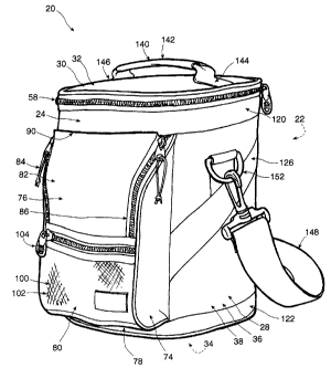
Referring to Figures 1, 2, and 3, an insulated pack having a
shapethatisgenerally
similar to a golf bag, but on a smaller scale, is shown generally as 20. It
has a leading
portion 22, a trailing portion 24, a pair of left and right hand side portions
26 and 28, a
top portion 30 having a lid 32, and a bottom portion 34. The major part of
pack20isan
CA 02243820 1998-07-23
6
insulated compartment 36 bounded by a modestly flexible soft shell insulating
wall, 38,
whose construction is shown in Figure 7. The breadth of pack 20, that is, the
overall width
when viewed from the leading or trailing directions, is about 8-v2" empty.
When
undeformed pack 20 has a gently bulging D-shaped cross section when seen from
above,
similar to a golf bag, although this may change somewhat when loaded. The
breadth is
roughly the same as the thickness of a middling to large size of golf bag.
Refernng briefly
to the detail of Figure 7, wall 38 has an outer covering 42 of webbed
construction, and
an internal closed cell foam layer 44 within covering 42.
Further, liner 46 is not, in the example illustrated, fixed to the bottom of
compartment 36, but can be pulled out of compartment 36 to an inverted
position (while
still remaining attached at rim 48) to facilitate washing with soap, and to
facilitate drying,
to discourage the grow of fungus and so on. Liner 46 has a single
circumferential seam
to join a bottom face, and a single wall seam running from the circumferential
bottom
seam to rim 48. In an optional alternative, liner 46 could be made from a
polymer that has
been impregnated with an antimicrobial compound prior to fabrication, a
desirable feature
for this kind of liner.
The top of compartment 36 is formed by generally D shaped lid 32. Lid 32 also
has a through section structure of a flexible reflective inner layer, 52, a
flexible skin in the
nature of a canvas or webbing covering, 54, and a flexible closed cell
insulation layer 55,
(similar to layer 44, above) captured inbetween. Lid 32 is joined to the main
body of pack
20, along the roughly straight side of the 'D' shape, by a hinge in the nature
of a flexible
fabric hinge 56, and a peripheral tracked closure in the nature of a zipper 58
having a pair
of opposed zipper cars.
Rim 48 has a resiliently spongy beaded lip 60 wrapped within the upper edge of
liner 46, adjacent to the set of zipper teeth 59 of zipper 58 that is mounted
to the main
body of pack 22. Lid 32 has a mating generally 'D' shaped peripheral lip 62
immediately
next to the set of zipper teeth 61 of zipper 58 mounted to lid 32. When zipper
58 is
20507246
CA 02243820 2000-11-16
7
closed, lip 62 is drawn down to bear on the outside surface of beaded hp 60,
encouraging
a sealing contact to be formed.
Within main compartment 36 a thermal transfer storage med~nn oolr>pattimernt
is
provided against a leading wall portion of insulating wall 38 by the use of a
sack 64 for
holding the thermal storage medium 66. Thermal storage medium 66 may be used
as a
source of heat to be transferred into the contents of compartment 36, that is,
to maintain
a warm temperature distribution in compartment 36. Alternatively, the thermal
storage
medium 66 can be used as a heat sink to maintain a cool, ck~illed, or fi»ng
temperature
distribution in the contents of compartment 36, as circumstances mayreqwr>r.
Saclc64has
an array of perforations 68 to allow air to circulate through sack 64 more
easily,
facilitating drying of sack 64 after washing.
The second major component of insulated pack 20 isanauxilia~ycompartment in
the nature of a valuables compartment 70, that is mounted to trailing portion
24,
externally of soft shelled insulating wall 38. Compartment 70 has a pair
ofleftandright
hand side portions 72 and 74 that are connected to and extend vertically
along, and
rearwardly from the trailing portion of insulating wall 38; and a single
piecehuilingwall
76 extending between the distal extremities of side portions 72 and 74. In the
preferred
embodiment wall 76 is, like the rest of cover 42, made of a 600
denierpolyfabric,
treated, as are all external surfaces of pack 20, to be stain and water .
Odl~wall
fabrics can be used, such as leather or leather-like vinyl.
Wall 76 has a lower or underside area 78 that meets, and is joinadto, the
trailing
portion of insulating wall 38. Underside area 78 forms the bottom of
oo~npartrner~ 70.
Wall 76 also has a medial, outer area 80 that extends roughly 2/5 of the way
up
compartment 70. An upper area 82 of wall 76, in the nature of a flap, is
oo~igt.~ous with
outer area 80 on one edge, and has closures on the remainder of its periphery.
Two of
those closures are left and right hand vertical zippers, 84 and 86, that join
with the
uppermost parts of the distal edges of side portions 72 and 74. The third is a
hook and
20824297.1
CA 02243820 2000-11-16
8
eye fabric closure 88 for releasably attaching end lip 90 of wall 76 to
insulated wall 38
just below rim 48.
Referring to Figure 3, in which closures 84, 86 and 88 are and tipper area
82 lies open, a first receptacle, in the nature of a soft sided, durable
fabric pocket 92 with
a covering flap 93 has a horizontal hook and eye fastener pact 95 rrlot>i~ed ~
its underside
just inside its lip, for mating with a vertically aligned mating hook and eye
fabric fastener
part 97, the combination of orientations providing an adjustable size, and
flexibility in
closure position. Pocket 92 is of a size for carrying a cellular
telephanehandset, having
a girth of roughly 5-tie" (roughly 1-n4" deep sides and 3" breadth) and a
depthof6-tie"
from bottom to lip. The interior of pocket 92 is lined with a cushioning
material. Pocket
92 can be used for other objects than cellular telephones such as for
s~glasses, a glasses
case, or other item.
An adjacent receptacle in the nature of a soft-sided, open top pocket 94,
without
cover, has a convenient size (roughly 4-n2" girth, 5-v2" depth) for holding a
deodorant
container, or other object of similar size. It can, for example, be used as a
sGo~a~ space
for a carrying strap. Adjacent to pocket 94 is a key holder in the nature of a
lanyard 96
having one end fastened within compartment 70 just below rim 48. At its other,
depending
end lanyard 96 has a quick-release spring clip 98 for hooking about the ring
of a key
chain. Use of a strap, such as lanyard 96, makes it easy to retrieve
lceys,rathexthanhaving
to fish around the bottom of compartment 70. The remaining enclosed space
within
medial outer area 80 and above underside area 78 has a height of roug~lly4
inches, and
a width of roughly 7 inches between the piping along the outer edges of
sidepoitions 72
and 74, leaving space for a wallet, or other items.
Other arrangements of closures are possible for awciliaiyoompactiner>t 70. A
single
three sided zipper closure, with one or two zipper cars could be used, and the
hook and
eye fastener eliminated. Other kinds of fasteners, such as laces and
g»rnriels, interference
fit seals, snaps, buttons, and so on are possible. The present arrangement is
preferred.
20824297.1
CA 02243820 1998-07-23
9
Similarly, other arrangements of receptacles and key holders, or like items
can be used,
although the present configuration is convenient, and preferred.
A vented, see-through pocket 100 is mounted externally to medial outer area
80,
S and is of a size for accommodating, for example, extra golf balls, gum,
candy bars or other
items. The open form mesh 102 permits objects in pocket 100 to dry more
easily. Pocket
100 is closed by a sliding closure in the form of zipper 104.
A main attachment, suitable, for example, for hanging pack 20 from a golf bag,
or
for clipping pack 20 to a golf bag or golf cart, is shown as a quick release
brass hook
fitting 110 is mounted to an upper region of pack 20 on leading portion 22.
Hook fitting
110 is free to revolve within its hinge fitting, 112, which itself is able to
swing up and
down within the confines of a broad loop of webbing 114.
A second attachment, suitable for tightening to another fastening location of
a golf
bag or golf cart, in the nature of an adjustable cinch strap 116 is mounted to
a lower
region of pack 20, also on leading portion 22. Strap 116 has a releasable
catch 118, and
can be used to tighten the lower region of pack 20 to a golf bag, golf cart,
or other object,
to restrain its swaying motion about the main attachment at hook fitting 110.
It is anticipated that a significant use of main insulated compartment 36 will
be for
carrying cans of liquid, such as carbonated beverages, fruit drinks, or beer,
whether or not
accompanied by ice cubes or crushed ice. Inasmuch as the preferred embodiment
illustrated has a capacity of 12 cans of 385 ml plus ice, a load of 10 to 12
Lbs. (50 to 55
l~ would not be unexpected. The height of the preferred embodiment illustrated
to the
lip of rim 48 is roughly 12 inches. Liner 46 is not taut when lying against
the inner walls
of compartment 36. That is, liner 46 has some slack, and is somewhat elastic
in any event.
Consequently load is taken up primarily, if not entirely, in soft shelled
insulating wall, 38,
and more specifically, principally in outer covering 42 of wall 38.
20507246
CA 02243820 1998-07-23
The main attachment at hook fitting 110 is able to carry the entire weight of
pack
20, and the second attachment, at cinch strap 116, inhibits swaying of pack 20
about the
first attachment. Outer covering 42 has an upper reinforcing band 120
extending
externally about the periphery of insulating wall 38 next to rim 48. A lower
reinforcing
5 band 122 extends externally about the bottom edge of pack 20 where leading
portion 22,
trailing portion 24, and side portions 26 and 28 meet bottom portion 34, that
is to say,
about the lower region of pack 20.
A pair of left and right hand web doubters, 124 and 126 commence at a
relatively
10 high location at the leading edges of respective side portions 26 and 28,
extend across the
surface of those sides, and terminate at a lower location on the trailing edge
of side
portions 26 and 28. That is, they extend from the leading edge of the upper
region, to the
trailing edge of a lower region of pack 20.
The attachment of hook fitting 110 to pack 20 is reinforced by an upper
lateral
reinforcing band 130, in addition to upper reinforcing band 120, the effect
being to spread
the stress concentration out. Lateral reinforcing band 130 ends at the leading
edges of
side portions 26 and 28, close to the leading ends of doubters 124 and 126,
yielding a
reinforced load path between the lower region of pack 20 and hook fitting 110.
Similarly, each end of cinch strap 116 is sewn under a vertical left or right
hand
root reinforcement 132 or 134, each of these in turn leading to either lower
reinforcing
band 122 or a lower lateral reinforcement band 136, whose ends reach to the
leading
edges of side portions 26 and 28.
For ease and comfort of carrying pack 20 by hand, lid 32 is provided with a
carrying handle 140 having a padded bail 142, and a pair of webbing feet 144
and 146 that
extend fully to opposite points on the periphery of lid 32, such that loads
carned through
handle 140 are transmitted not only through the outer covering layer of lid 32
but also
through the reinforcement of feet 144 and 146. At the edge of lid 32 the
presence of
20507246
CA 02243820 2000-11-16
11
upper reinforcing band 120 helps to spread the load more evenly to and from
the vertical
sidewalls formed by portions 22, 24, 26, and 28. Alternatively, pack
20canbecaniedby
a shoulder strap 148 fastened by spring clips to D-shaped rings 150 and
152,mou~sdon
either of sides 26 and 28.
Left hand side portion 26 is provided with a trapezoidally shaped exte>nal
pocket
154 having a breathing, see-through mesh 156 similar to mesh 102. A soo~c~d,
ormap,
placed in this pocket can be seen for retrieval. Lip 158 of pocket 154 is set
on a rake
angle, yielding a somewhat larger opening for sliding a scorecard in, without
having as
carefully to fit it into a narrow opening as might otherwise be the case for a
square cut
pocket. .
Refernng to Figures 4 and 5, a second insulated pack, is shown g~allyas 170.
In this embodiment, pack 170 is of a size for carrying 5 cans. It has a
leadingpoiticn 172,
a trailing portion 174, a pair of left and right hand side portions 176 and
178, a top
portion 180 having a lid 182, and a bottom portion 184. The major part ofpack
170isan
insulated compartment 186 bounded by a modestly flexible soft shellngwal),188,
whose wall construction is the same as that shown in Figure 7 and disal~ad
above. The
breadth of pack 170, that is, the overall width when viewed from the leading
or trailing
directions, is about 6-t~2" empty. When undeformed pack 170 has a gently
bulging D-
shaped cross section when seen from above again, not ~rrilar in general
appearance to
a golf bag. The breadth is roughly the same as the thickness of a small
sizeofgolfbag,
and, is such that pack 170 can nest comfortably within oorr>pactrnent 36
ofpack20. This is
shown in Figure 6.
The top of compartment 186 is formed by generally D shaped fid 182. lid 182
has
the same layered construction as lid 32. Lid 182 is joined to the
mainbodyofpack 170,
along the roughly straight side of the 'D' shape, by a hinge in the nahue of a
flexible fabric
hinge 206, and a peripheral tracked closure in the nature of a zipper 208
having apair of
opposed zipper cars. The manner of closing lid 182 on compartment 186 ofpack
170is
20824297.1
CA 02243820 2000-11-16
12
the same as for lid 32 of pack 20. Further, the same kind of substantially
impermeable
liner and thermal storage medium are used. The thermal storage medirun is held
in a sack
like sack 64.
The second major component of insulated pack 170 is an auxilia<y compartment
in the nature of a valuables compartment 220, that is mounted to trailing
portion 174,
externally of soft shelled insulating wall 188. Compartment 220 has a
generally
downwardly opening, U-shaped member 221 that has pair of left and right hand
side
portions 222 and 224 that are connected to and extend vertically akmg aril
rearwardly
from the trailing portion of insulating wall 188 and a top cross portion 223
extending
between them. Compartment 220 also has a single piece trailing wall 226
extending
between the distal extremities of side portions 222 and 224. Wall 226 is made
ofcanvas.
Wall 226 has a lower or underside area 228, that meets and is joined to the
trailing portion
of insulating wall 188. Underside area 228 forms the bottom and lower trailing
face of
compartment 220. Wall 226 also has an upper area 232, being a flap contiguous
with
underside area 228 on one edge. Upper area 232 has a three sided wrap-amur~d
closure,
being a zipper 234 that joins the corresponding edge of U-shaped member 221.
As
described above in the context of pack 20, compartment 220 has ii>temal
reoehhacles lined
with cushioning for receiving valuables, glasses, keys, and so on.
A main attachment, suitable, for example, for hanging pack 170 fi>xn a
golfbag,
or for clipping pack 170 to a golf bag or golf cart, is shown as a quick
releaseblasshook
fitting 240, mounted to an upper region of pack 170 on leading portion 172.
Hook fitting
240 is free to revolve within its hinge fitting, 242, which itself is able to
swing up and
down within the confines of a broad loop of webbing 244.
A second attachment, suitable for tightening to another fasta>ing k>~ion of a
golf
bag or golf cart, in the nature of an adjustable cinch strap 246 is mounted to
a lower
region of pack 170, also on leading portion 172, but in this case being rooted
at the
outside edges of leading portion 172 where they meet the leading
edgesofsideportions
20824297.1
CA 02243820 2000-11-16
13
176 and 178. Strap 246 has a releasable catch 248, and can be used to tighten
the lower
region of pack 170 to a golf bag, golf cart, or other object, to res~ain its
swaying motion
about the main attachment at hook fitting 240.
Outer covering 192 has an upper reinforcing band 250 exte~g externally about
the periphery of insulating wall 188 next to rim 198. A lower reinforcing band
252
extends externally about the bottom edge of pack 170 where leading potion 172,
trailing
portion 174, and side portions 176 and 178 meet bottom portion 184, that is to
say, about
the lower region of pack 170.
A pair of left and right hand doublers, 254 and 256 commence atarelativelyhigh
location at the leading edges of respective side portions 176 and 178, extend
acx~ss the
surface of those sides, and terminate at a lower location on the trailing edge
of side
portions 176 and 178.
The attachment of hook fitting 240 to pack 170 is reinforced by an lateral
reinforcing band 260, in addition to upper reinforcing band 250,
theeffectbeangto spread
the load out. Lateral reinforcing band 260 ends at the leading edges of side
portions 176
and 178, close to the leading ends of doubters 254 and 256,
yieldingareinfolcedloadpath
between the lower region of pack 170 and hook fitting 240.
Lid 182 is provided with a carrying handle 270 having a padded bail 272, arid
a
pair of webbing feet 274 and 276 that extend fully to opposite points on
thepyof
lid 182, such that loads carned through handle 270 are transmitted not
onlyd~ughthe
outer covering layer of lid 182 but also through the reinforcement of feet 274
and 276.
At the edge of lid 182 the presence of upper reinforcing band 250 helpsto
spreadthe load
more evenly to and from the vertical sidewalls formed by portions 172,174,176,
and 178.
20824297.1
CA 02243820 2000-11-16
14
Left hand side portion 176 is provided with a trapezoidally sh~adextemalpocket
284 having a breathing, see-through mesh 286 similar to mesh 102. Lip 288 of
pocket
284 is set on a rake angle.
A preferred embodiment has been described in detail andarnnnberofalternatives
have been considered. As changes in or additions to the above described
embodiments
may be made without departing from the nature, spirit or scope of the
invention, the
invention is not to be limited by or to those details, but only by the
appaxlad claims or
their equivalents.
20824297.1