Note: Descriptions are shown in the official language in which they were submitted.
CA 02256908 1998-12-21
1
SNOW WINGS
The present invention relates to a pair of wing
assemblies for attachment to known snow clearing machines
which employ an impeller, such as snow throwers for
domestic use. Typically, the impeller is contained within
a housing with a forward opening therein to facilitate the
feeding of snow to the impeller as the snow thrower is
operated.
The use of blades or wings in conjunction with a
snow thrower is known. For example, Canadian Patent No.
671,590 granted to Worrel discloses a pair of forwardly
extending side plates detachably connected to a snow
thrower. A disadvantage of this type of blade, however, is
that the flat design of the blades does not assist in
scooping the snow and causing it to roll into the path of
the impeller. A further disadvantage of this type of blade
is that the fixed nature of the blades makes them
inconvenient to attach or remove and ill-adapted to
different snowfall conditions.
Another type of device, such as that disclosed in
Canadian Patent No. 1,161,462 granted to Kelly, is an
apparatus mounted onto the arms of a front end loader to
scoop snow into an intake opening when the apparatus moves
forward. Hydraulic rams are used to raise and lower wings
to increase maneuverability of the vehicle. This type of
device also suffers from being difficult to remove and
attach and is limited to a single mode of operation.
CA 02256908 2000-OS-O1
2
Accordingly, it is desirable to be able to
increase the utility and versatility of domestic snow
clearing devices by providing the operator with a choice of
modes of operation to better suit the task at hand while
providing a simple, convenient and inexpensive positioning
mechanism. It is also desirable to provide a shaped wing
adapted to effectively scoop snow and feed it to the
impeller of the snow thrower. It is further desirable to
provide for the convenient storage of the snow clearing
machine without the need to remove the wing assemblies.
The present invention provides for a pair of wing
assemblies for attachment to snow removal equipment having
a housing with a forward opening for feeding snow to an
impeller, each wing assembly being attachable to an
opposite side of the housing and comprising: a wing having
a front surface, a back surface, and top, bottom and side
edges, the front surface being concave about a horizontal
axis; a locking arm having first and second end portions;
and a rack having a front portion and a rear portion, the
rack being fixed in a horizontal orientation to a side of
the housing with the front portion proximate to the forward
opening; a proximal side edge of the wing being pivotally
connected to a front portion of the rack so that the wing
may move in a horizontal plane and a first end portion of
the locking arm being pivotally connected to the back
surface of the wing in spaced relation from the front
portion of the rack, a second end portion of the locking
arm being capable of being selectively fixed to the rack in
a plurality of positions so as to lock the wing in at least
a first and a second operative position and the locking arm
CA 02256908 2000-OS-O1
3
being capable of disengagement from the wing or rack so as
to permit the wing to assume an inoperative third position.
The present invention further provides for snow
removal equipment having a housing with a forward opening
for feeding snow to an impeller and provided with a wing
assembly attached to each side of the housing, each wing
assembly comprising: a wing having a front surface, a back
surface, top, bottom and side edges, the front surface
being concave about a horizontal axis; a locking arm
having first and second end portions; and a rack having a
front portion and a rear portion, the rack being fixed in
a horizontal orientation to a side of the housing with the
front portion proximate to the forward opening; a proximal
side edge of the wing being pivotally connected to a front
portion of the rack so that the wing may move in a
horizontal plane and a first end portion of the locking arm
being pivotally connected to the back surface of the wing
in spaced relation from the front portion of the rack, a
second end portion of the locking arm being capable of
being selectively fixed to the rack in a plurality of
positions so as to lock the wing in at least a first and a
second operative position and the locking arm being capable
of disengagement from the wing or rack so as to permit the
wing to assume an inoperative third position.
Alternatively, the locking arm may be capable of
disengagement from the wing so as to assume an inoperative
storage position.
A single wing assembly is contemplated within the
scope of the invention, for example, for the purposes of
replacement parts. Accordingly, another aspect of the
invention provides snow removal equipment having a housing
CA 02256908 2000-OS-O1
4
with a forward opening for feeding snow to an impeller and
provided with a wing assembly attached to each side of the
housing, each wing assembly comprising:
a wing having a front surface, a back surface,
top, bottom and side edges, the front surface being concave
about a horizontal axis;
a locking arm having first and second end
portions; and
a rack having a front portion and a rear portion,
the rack being fixed in a horizontal orientation to a side
of the housing with the front portion proximate to the
forward opening;
a proximal side edge of the wing being pivotally
connected to a front portion of the rack so that the wing
may move in a horizontal plane and a first end portion of
the locking arm being pivotally connected to the back
surface of the wing in spaced relation from the front
portion of the rack, a second end portion of the locking arm
being capable of being selectively fixed to the rack in a
plurality of positions so as to lock the Wing in at least
a first and a second operative position and the locking arm
being capable of disengagement from the wing or rack so as
to permit the wing to assume an inoperative third position.
CA 02256908 1998-12-21
The invention, as exemplified by a preferred
embodiment, will now be described with reference to the drawings
in which:
Figure 1 is a side elevation view of a wing assembly
5 shown as attached to a snow thrower;
Figure 2 is a perspective view showing details of
the wing assembly;
Figure 3 is a plan view of the wing assembly in a
first operative position;
Figure 4 is a plan view of the wing assembly in a
second operative position; and
Figure 5 is a plan view of the wing assembly in an
inoperative third position.
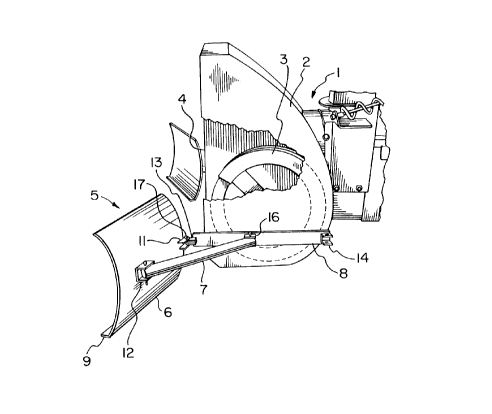
As seen in Figure 1, in the embodiment of the
invention shown, a snow blower (1) has a housing (2) containing
an impeller (3) . Snow is fed to the impeller (3) via intake
opening (4). A wing assembly (5) comprises a wing (6), a locking
arm ( 7 ) and a rack ( 8 ) .
The wing (6) is concave, when viewed from the side,
in order to better channel snow into the intake opening (4) . The
wing may be made of plastic or metal, such as aluminum. The wing
(6) is provided with an integral plate-like gliding member (9)
which protrudes from the bottom edge of the wing (6) and is
adapted to facilitate the gliding of the wing (6) along the
ground. The gliding member (9) also serves, in cooperation with
the concave shape of the wing (6) , to gather snow and roll a.t
into the intake opening (4). The width of the wing (6), measured
from side to side, is slightly less than half the width of the
CA 02256908 1998-12-21
6
intake opening (4) so as to facilitate convenient storage of the
snow blower (1) with the wings (6) folded in a storage position.
The back surface of the wing (6) is provided with
a first mounting bracket (11) at the proximal edge of the wing
(6) and a first locking bracket (12) spaced from the first
mounting bracket (11).
The racks (8) are mounted onto opposite sides of the
housing (2) in a horizontal orientation using screws or bolts.
Each rack (8) is provided at the end nearer the intake opening
(4) with a second mounting bracket (13) to permit mounting of a
wing (6) thereon. Each rack is also provided with a second
locking bracket (14) near the other end of the rack and a third
locking bracket (16) between the second mounting bracket (13) and
the second locking~bracket (14) in spaced apart relation from
each.
The first mounting bracket (11) and the second
mounting bracket (13) cooperate to form a hinge when secured with
a first drop pin (17).
As shown in Figures 1 and 2, the first, second and
third locking brackets (12, 14, 16) are C-shaped, each having a
flat middle portion (18) and flat end portions (19), the end
portions (19) being perpendicular to the middle portion and
parallel to each other so as to define a recess (21) . The middle
portion (18) is provided with a welding hole (22) to facilitate
a weld mount. The end portions (19) are provided with centrally
placed pin holes (23). The middle portion (18) of the first
locking bracket (12) is fixed to the back of the wing (6) by
fixing means, namely welding, so that the end portions (19) are
CA 02256908 1998-12-21
7
horizontally oriented and disposed one above the other with pin
holes (23) vertically aligned. The middle portion (18) of the
first and second locking brackets (14, 16) are fixed to the rack
(8) by fixing means, namely welding, so that the end portions
(19) are horizontally oriented and disposed one above the other
with pin holes (23) vertically aligned.
A first end portion (24) of the locking arm (7) is
provided with a first hole (26) through the locking arm (7). A
second end portion (27) of the locking arm (7) is provided with
a second hole (28) through the locking arm (7) and parallel to
the first hole (26). The first end portion (24) of the locking
arm (7) is received in the recess (21) of the first locking
bracket (12) so that the first hole (26) is aligned with pin
holes (23) of the first locking bracket (12). A second drop pin
(29) is inserted in the passage defined by the first hole (26)
and pin holes (23) of the first locking bracket (12) thereby
pivotally attaching the locking arm (7) to the wing (6),
permitting rotation of the wing (6) in a horizontal plane. This
movement is in the same plane as permitted by the hinge formed
by the first mounting bracket (11) and the second mounting
bracket (13).
In a first configuration, each locking arm assumes
a first operative position wherein the second end portion (27)
of each locking arm is attached to the respective third locking
bracket (16) by receiving the second end portion (27) of the
locking arm (7) in a recess (21) defined by the third locking
bracket (16) so that the second hole (28) of the second end
portion (27) of the locking arm (7) is aligned with the pin holes
CA 02256908 1998-12-21
8
(23) of the third locking bracket (14) and inserting the third
drop pin (31) through the passage thus defined. In this
arrangement, the wing (6) is fixed and no longer permitted to
move in a horizontal plane. The length of the locking arm (7)
and the placement of the first and third locking brackets (12,
16) are such that the wing (6) is angled forwardly. In this
preferred embodiment each wing (6) is angled at about 40 to 60
degrees, preferably approximately 45 degrees, from the side of
the housing (2). Referring to Figure 3, the pair of wings (6)
thus diverge forwardly so as to increase the catchment area of
the snow thrower and increasing the amount of snow fed to the
impeller. This permits a mode of operation which is particularly
suitable for use after a light snowfall to increase the
efficiency of eachrpass thereby reducing the number of passes
required.
In a second configuration, each locking arm assumes
a second operative position wherein the second end portion (27)
of each locking arm (7) is attached to the respective second
locking bracket (14) by receiving the second end portion (27) of
the locking arm (7) in a recess (21) defined by the second
locking bracket (23) so that the second hole (28) of the second
end portion (27) of the locking arm (7) is aligned with the pin
holes (23) of the second locking bracket (14) and inserting the
third drop pin (31) through the passage thus defined. In this
arrangement, the wing (6) is fixed and no longer permitted to
move in a horizontal plane. The length of the locking arm (7) and
the placement of the first and second locking brackets (12, 14)
are such that the wing (6) is angled rearwardly. In this
CA 02256908 1998-12-21
9
preferred embodiment each wing (6) is angled at about 40 to 60
degrees, preferably approximately 45 degrees, from the side of
the housing (2) . Referring to Figure 4, the pair of wings (6)
thus diverge rearwardly so as to form plows to augment the action
of the impeller (3). Snow is conveniently pushed to the sides
forming banks. This permits a mode of operation suitable for
clearing a path through snow in a single pass that is wider than
is possible using an unmodified snow thrower.
As an alternative to the first and second operative
positions, a hybrid configuration may also be adopted in which
a first wing (6) assumes a first operative position, as described
above, so that it is angled forwardly and a second wing (6)
assumes a second operative position, as described above, so that
it is angled rearwardly. In this hybrid configuration, the first
wing (6) acts to increase the amount of snow fed to the impeller
(3) while the second wing (6) acts as a plow to augment the
action of the impeller (3).
Referring to Figure 5, in a third configuration,
each arm assumes an inoperative third position wherein each
locking arm (7) is disengaged from the rack (8) by removing the
third drop pin (31) and folding each locking arm (7) parallel and
adjacent to the back surface of the wing (6) and folding each
wing (6) in front of and perpendicular to the sides of the
housing (2) of the snow thrower (1). This inoperative position
thus facilitates storage of the snow thrower (1) mounted with
wings (6) without the inconvenience of removing the wing
assemblies (5). In this preferred embodiment, the concave shape
CA 02256908 1998-12-21
of the wing (6) approximately follows the curvature of the
impeller (3) so as to make the entire apparatus more compact.
An alternative inoperative storage position to that
shown in Figure 5 is a configuration wherein each locking arm (7)
5 is disengaged from the wing (6) by removing the second drop pin
(29) and folding each locking arm adjacent and parallel to a
respective rack (8). Each wing (6) can then be folded in front
of the snow thrower, as in Figure 5, or alternatively, folded
back so as to be adjacent and substantially parallel to a
10 respective rack (8).