Note: Descriptions are shown in the official language in which they were submitted.
CA 02273072 1999-05-27
WO 98/26831 PCT/US97/23641
1
TEMPERATURE REGULATING CATHETER AND METHODS
BACKGROUND OF THE INVENTION
The present invention relates generaliy to the
regulation cf the temperature of a fluid that is to be
delivered to a specific target location within a body
structure. More particuiarly, the invention provides methods
and apzaratus for alterina the temperature of a fluid that I's
to be delivered to the target location while the fluid is
within the natient.
On many occasions, the temperature of a fluid within
a patient needs to be regulated. For example, in some medical
procedures, various fluids, such as solutes or drugs, are
delivered to target locations within the body. The desired
temperature of these fluids upon delivery may vastly differ
from t-he storage temperature. In such cases, it is therefore
desirable to heat or cool the fluid before it reaches the
target location. Althouah possible to heat or cool the fluid
outside of the patient, such a procedure can be cumbersome and
require elaborate eauipment.
As another example, fluids at various temperatures
mav be introduced to a target location within a patient to
regulate the temperature of a localized area within a body
structure. One particular application where the heating or
coolina of a specific area within a bodv structure is
desirable is in the field of neurosurgery. In many cases, it
is desirable to cool a specific area within the brain nrior to
perfcrming a surgical procedure.
As a further example, the temperature of bodv fluids
may be regulated to control the patient's body temperature.
?5 The reaulation of the patient's body temperature is
particularl.,- useful in treating patient's suffering from
either hypothermia or hyperthermia.
CA 02273072 1999-05-27
WO 98/26831 PCTIUS97/23641
2
Under ordinary circumstances, the thermal reaulatory
system of the human body maintains a near constant temperature
of about 37 C (98.5 F). Heat lost to the environment is
precisely balanced by heat produced within the body.
Hypothermia is a condition of abnormally low body temperature.
Hvpothermia can be clinically defined as a core body
temperature of 35 C or less. Accidental hypothermia results
when heat loss to the environment exceeds the bod_v's ability
to produce heat internally. Hypothermia may also occur in
patients exposed to mild cold stress whose thermal regulatory
ability has been lessened due to injury and illness.
Hypothermia of either type is a dangerous condition
which can have serious medical conseauences. In particular,
hypothermia interferes with the ability of the heart to pump
blood. Hypothermia may be fatal for this reason alone.
Additionally, low body temperatures seriously interfere with
the enzymatic reactions necessary for blood clotting. This
sometimes results in bleeding that is difficult to control,
even when normal clotting factor levels are present. These
effects and other adverse consequences of hypothermia lead to
drastically increased mortality rates both among victims of
trauma and in patients undergoing surgery.
Hyperthermia is a condition of abnormally high body
temperature and mav result from exposure to a hot environment,
overexertion, or fever. Body core temperatures can range from
38 C to 41 C due to fever and may be substantially higher in
cases of exposure and overexertion. Like hypothermia,
hyperthermia is a serious condition and can be fatal-.
Simple methods for treating both hypothermia and -
hyperthermia have been known since early times. In the case
of hypothermia, such methods include wrapping the patient in
blankets, administering warm fluids by mouth, and immersing
the patient in a warm water bath. To treat hyperthermia, some
have proposed immersion of the patient in a cool water bath or
the administration of cool fluids. However, such methods can
have serious drawbacks and limited effectiveness.
One particular catheter structure which has been
developed to treat a patient suffering from either hvpothermia
CA 02273072 2006-02-28
3
or hyperthermia is described in U.S. Patent No. 5,486,208,
Such a catheter has the ability to heat or cool a
liquid that is circulated through a catheter body.
Although such a catheter has been shown to be
generally effective in the treatment of both hypothermia and
hyperthermia, some improvements are still desired. For
example, it would be desirable if such a catheter were more
versatile to allow for the temperature of various fluids
introduced into the body to be regulated. In this manner, the
temperature of an introduced fluid could be more closely
controlled at the point of introduction. It would be further
desirable if a catheter structure and methods were provided
for regulating the temperature of a localized region within a
body structure prior to performing a medical procedure on the
body structure.
SUMMARY OF THE INVENTION
The invention provides methods and apparatus for
regulating the temperature of a fluid while the fluid is
within the patient. Such a fluid can include, for example, an
externally introduced fluid, an internal body fluid, or both.
To provide such features, the present invention in one
exemplary embodiment provides a catheter comprising a catheter
body having a proximal end and a distal end. At least one
lumen defining a luminal wall extends between the proximal end
and the distal end. A temperature altering mechanism is
disposed within the catheter body which heats or cools the
luminal wall to alter the temperature of a fluid passing
through the lumen.
The temperature altering mechanism may comprise a
heater or a cooler, and is preferably located at a temperature
altering area. The temperature altering area may be located
anywhere along the catheter body and in some embodiments will
preferably be located near the distal end of the catheter. In
another aspect, the temperature altering mechanism is
preferably disposed near the luminal wall to heat or cool the
luminal wall without substantial heating of an outer surface
CA 02273072 1999-05-27
WO 98/26831 PCT/US97/23641
4
of the catheter body. In this manner, a fluid mav be
externally introduced into a patient through a proximal port
and be heated or cooled at the temperature altering region
without heating or cooling of the outer surface ol" the
catheter body. In this way, when the fluid exits the distal
end of the catheter body, the fluid will be within a desired
temperature range so that only a particular location within
the patient which is near the distal end of the catheter will
be heated or cooled.
In one exemplary aspect, a plurality of orifices are
disposed within the catheter body to permit a bodv fluid to
flow through the orifices and into the lumen. As the body
fluid passes through the temperature altering region, the
temperature of the body fluid is altered. In this manner, the
catheter is provided with the versatility of altering the
temperature of an externally introduced fluid, an internal
body fluid, or both. In a particular aspect, a one-way valve
is associated with each orifice to prevent the body fluids
from entering into the lumen when an external fluid is
injected into the lumen from the proximal port. The valves
are configured to open when the pressure of the body fluids
outside of the catheter body are greater than the pressure
within the lumen. In this manner, body fluids will freely
flow into the lumen for heating or cooling until a fluid is
injected into the lumen from outside of the patient to close
the valves. In one particular aspect, the valves comprise
flaps that are attached to the luminal wall and will remain
open due to the pressure exerted by the body fluid u~ntil an
external fluid is injected into the lumen.
The temperature altering mechanism may be configured
in a variety of ways. For example, the temperature altering
mechanism may comprise a resistive heater employing either
electrical or radio frequency current. Various chemicals may
also be employed to heat or cool the luminal wall.
Alternatively, laser energy may be employed to regulate the
temperature of the catheter body. In one particularly
preferable aspect, the temperature altering mechanism
comprises a first path which is adjacent the luminal surface
CA 02273072 1999-05-27
WO 9,8/26831 PCT/US97/23641
and a second path which is adjacent an outer surface of the
catheter body. in this way, a heat transfer fluid may be
introduced into a heat transfer fluid port where it will flow
through the first fluid path adjacent the luminal wall. As
5 the heat transfer fluid flows through the first path, heat is
transferred to or from the fluid flowing within the lumen.
The heat transfer fluid is then circulated through the second
path where it will exit the catheter body outside of the
patient.
The invention further provides an exemplary method
for altering the temperature of a liquid medium while the
liquid medium is within a patient. According to the method, a
catheter is provided having a catheter body with a proximal
end and a distal end. At least one lumen extends between the
proximal end and the distai end, and an internal temperature
altering region is provided. The temperature altering region
may be located anywhere between the proximal end and the
distal end, and in some cases will preferably be located near
the distal end. With this configuration, the catheter is
introduced into a body structure until the temperature
altering region is near a target area within the body
structure. A liquid medium is introduced into the lumen, and
the temperature of the liquid medium is altered while passing
through the temperature altering region. In this way, the
temperature of the liauid medium is altered when delivered to
the target area.
In one exemplary aspect, the catheter is configured
such that the liquid medium may be introduced to the_lumen at
the proximal end or introduced into the lumen through orifices
disposed within the catheter body near the temperature
altering region. In this way, a liquid medium may be
introduced into the lumen from outside the patient while body
fluids may also be introduced into the lumen by perfusing
through the orifices. This allows various fluids, such as
solutes, drugs, blood substitutes and the like to be
externally injected into the catheter and then be heated or
cooled before reaching the target location. Further, various
CA 02273072 1999-05-27
WO 98/26831 PCT/US97/23641
6
body fluids, such as blood, may be heated or cooled while
within the patient.
In one exemplarv aspect, the method provides for
preventing the body fluids from entering into the lumen while
a liquid medium is externally introduced into the lumen.
Following the introduction of the external liquid medium, the
method provides for allowing body fluids to again enter into
the orifices where they pass through the temperature altering
region.
Configuration of the catheter in this manner allows
for the performance of various medical procedures. For
example, the distal end of the catheter may be positioned near
a target site where a drug or solute is to be introduced.
=nclusion of the temperature altering region allows for the
drug cr solute to be heated or cooled to a desired temperature
upon deliverv. Other fluids may also be introduced to the'
temperature altering region to regulate the temperature of a
particular location within a body structure prior to
performing a surgical procedure. For example, such a method
may be employed to cool a particular vessel within the brain.
Inclusion of the orifices also allows for convenient
temperature regulation of the patient's blood so that a
patient suffering from either hypothermia or hyperthermia may
be treated.
In one exemplary aspect, the temperature of the
liquid medium is altered without substantial alteration of the
temperature of an outside surface of the catheter body. In
another aspect, the temperature of the liquid medium-is
preferably heated by a temperature in the range from about -
38 C to about 40 C. In a further aspect, the temperature of a
liquid medium will preferably be cooled by a temperature that
is in the range from about 36 C to about 30 C.
BRIEF DESCRIPTION OF THE DRAWINGS
Fig. 1 depicts a distal end of a catheter according
to the present invention which is inserted into a vessel of a
patient.
CA 02273072 1999-05-27
WO 98/26831 PCT/US97/23641
7
Fig. 2 is a cross-sectional side view of the
catheter of Fig. 1 taken along lines 2-2 and depicting a
temperature altering region.
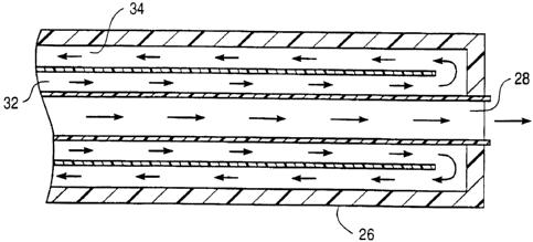
Fig. 3 is a side view of an exemplary catheter for
heatina or cooling a fluid passing through an internal lumen
according to the invention.
Fig. 4 is a more detailed view of a distal end the
catheter of Fig. 3.
Fig. 5 is a side view of an alternative catheter for
heatina a fluid passing through an internal lumen according to
the invention.
Fig. 6 is a side view of the catheter of Fig. 5
taken along lines 6-6.
Fig. 7 is a side view of another alternative
embodiment of a catheter for heating or cooling a fluid
passincr throuah an internal lumen and having a plurality of
perfusion orifices for allowing body fluids to enter into the
internal lumen according to the invention.
Fig. 8 is a cutaway side view of a portion of the
catheter of Fig. 7 showing a plurality of flaps which are
closed to prevent body fluids from entering into the internal
lumen when a liquid is externally injected into the lumen.
Fig. 9 illustrates the catheter of Fig. 8 showing
the flaps opening to allow body fluids to enter into the
internal lumen when no fluids are externally injected into the
lumen.
DESCRIPTION.OF THE SPECIFIC EMBODIMENTS -
The invention provides methods and apparatus for -
regulating the temperature of a fluid that is to be delivered
to a target location within a body structure while the fluid
is within the patient. The regulation of the fluid's
temperature in this manner lends itself to a variety of
applications including heating or cooling the temperature of a
drug or solute before its delivery to a target site.
Regulation of the temperature of the injected fluid may also
find use in regulating the temperature of the target location
itself in preparation for various medical procedures,
CA 02273072 1999-05-27
WO 98126831 PCT/US97/23641
8
including neurosurgicai procedures within the brain. Further,
the methods and apparatus allow for a patient's body
temperature to be controlled by warming or cooling the
patient's blood in situ. By warming or cooling the patient's
blood, the patient's body temperature may thereby be increased
or decreased as desired. Such methods and apparatus therefore
provide a convenient therapy for treating hypothermia or
hyperthermia.
Fig. 1 depicts a distal end 10 of a catheter 12
according to the present invention. The catheter 12 has been
inserted through the patient's skin into a blood vessel BV.
Blood flow through the vessel is indicated by a set of arrows
F. At distal end 10 is a temperature altering region 14, it
being appreciated that the temperature altering region may be
located anywhere between the proximal end and the distal end.
As best shown in Fig. 2, catheter 12 includes an
internal lumen 16. A temperature altering mechanism 18 is
provided adjacent the luminal wall of lumen 16 at the
temperature altering region 14. For convenience of
discussion, temperature altering mechanism 18 is illustrated
schematically and may comprise a variety of mechanisms that
are employed to either heat or cool the luminal wall of lumen
16 to heat or cool the fluid passing through lumen 16 at the
temperature altering region 14. Exemplary mechanisms for
heating or cooling the luminal wall include heated or cooled
fluids passing through catheter 12 near the luminal wall,
resistive elements disposed within catheter 12, laser energy
that is supplied to the temperature altering region,- various
chemicals disposed within the catheter body, thermoelectric -
crystal, and the like. Use of such mechanisms allow fluids
passing through lumen 16 at the temperature altering region 14
to have their temperature altered so that they will be within
a desired range when exiting catheter 12.
Catheter 12 may be manufactured in various sizes
depending upon the particular application. For most uses, it
will have a length in the range from about 30 cm to about 130
cm and a diameter in the range from 6 to 12 French (1 French =
0.33 mm). Catheter 12 will preferably be flexible to allow
CA 02273072 2006-02-28
9
the catheter to be moved through various vessels withiri a
patient, preferably with the assistance of a guidewire..
Techniques for inserting catheters into various
blood vessels are well known among medical personnel.
Although the method of the present invention will probably be
most commonly employed in a hospital, the procedure need not
be performed in a operating room. The apparatus and
procedures are so simple that the catheter may be inserted and
treatment may begin in some cases even in an ambulance or in
the field.
Temperature altering mechanism 18 will preferably be
configured to heat a fluid passing through the temperature
altering region so that its temperature will be heated by at
least 5 C to about 42 C. When cooling a fluid, the
temperature altering mechanism 18 will preferably be
configured to cool the fluid by at least 7 C to about 30 C.
Temperature altering mechanism 18 should be designed to
optimize the rate of heat transfer between the catheter and a
fluid flowing through the internal lumen. Further, the
temperature of the catheter should be carefully controlled to
prevent undesirable chemical changes within the blood. This
is especially important when applying heat to the blood. as
blood is readily denatured by even moderately high
temperatures. The temperature of the luminal wall for warming
blood should generally not exceed about 42 C to 43 C. The
amount of energy to be supplied to heat a patient's core body
temperature is described in U.S. Patent No. 5,486,208,
The temperature altering mechanism 18 will
preferably be arranged within catheter 12 so that the
temperature of the luminal wall may be heated or cooled
without substantial direct heating of an outer surface of the
catheter 12. In this way, catheter 12 may be employed to
selectively heat or cool a specific target site by simply
positioning the distal end of the catheter at the target site
and introducing a fluid through lumen 16.
Referring now to Fig. 3, an exemplary embodiment of
a catheter 20 which circulates a heat transfer fluid to alter
CA 02273072 1999-05-27
WO 98/26831 PCT/US97/23641
the temperature of a fluid passing through the catheter will
be described. Catheter 20 comprises a catheter body 22 having
a prbximal end 24 and a distal end 26. A lumen 28 extends
between proximal end 24 and distal end 26. At proximal end 24
5 is a proximal port 30 through which various fluids may be
introduced into lumen 28 from outside of a patient. Passing
throuah catheter body 22 is a first fluid path 32 and a second
fluid path 34. A first port 36 is in communication with first
fluid path 32 and a second port 38 is in communication with
10 second fluid path 34. In this manner, a heated or cooled heat
transfer fluid may be introduced into first port 36 where it
passes through first fluid path 32 adjacent lumen 28. As the
heat ~ransfer fluid passes through first fluid path 32, heat
is transferred either to or from a fluid nassing throuah lumen
28 to heat or cool the fluid to a desired temperature before
exiting catheter body 22. After passing through first rlui'd
path 32, the heat transfer fluid circulates back through
catheter body 22 through second fluid path 34 where it exits
second port 38.
Fig. 5 depicts an embodiment of a catheter 40 which
employs resistive heating to heat a fluid passing through the
catheter. Catheter 40 comprises a catheter body 42 having a
proximal end 44 and a distal end 46. A lumen 48 passes
through catheter boczv 42 between proximal end 44 and distal
end 46. A proximal port 50 is provided to facilitate the
introduction of fluids into lumen 48 from outside a patient.
Disposed within catheter body 42 near lumen 48 are a plurality
of wires 52 (See also Fig. 6). Wires 52 exit cathet-er body 42
through a port 54. Wires 52 may be connected to either a DC -
or low frequency AC power supply. As electrical current
passes through wires 52, some of the energy is dissipated as
heat to heat the luminal wall. Alternatively, a radio
frequency or RF power supply may be employed to supply power
to electrodes disposed within catheter body 42 to heat the
luminal wall.
Referring now to Figs. 7 and 9, an exemplary
embodiment of a catheter 56 which may be employed to heat or
cool an externally injected fluid, to heat or cool a body
CA 02273072 2006-02-28
fluid in situ, or both. Catheter 56 comprises a catheter body
58 having a proximal end 60 and a distal end 62. Extending
between proximal end 60 and distal end 62 is a lumen 64. A
proximal port 66 is provided at proximal end 60 and allows
various fluids to be injected into lumen 64 while port 66 is
positioned outside a patient. At distal end 62 is a
temperature altering region 68 which includes a temperature
altering mechanism (not shown). The particular temperature
altering mechanism may comprise any of those previously
described with the other embodiments set forth herein. In
this manner, a fluid which is injected into port 66 will pass
through lumen 64 and have its temperature altered when passing
through temperature altering region 68 in a manner similar to
that previously described with other embodiments.
Catheter body 58 includes a plurality of perfusion
orifices 70 which extend through the wall of the catheter body
to provide fluid paths to lumen 64. As shown by the arrows in
Fig. 7, a body fluid, such as blood, may pass through orifices
70 and into lumen 64 where it will have its temperature
altered at region 68 so that the temperature of the body fluid
will be within a desired range when exiting catheter bcidy 58
at distal end 62 as shown.
As best shown in Figs. 8 and 9, attached to t.he
luminal wall of catheter body 58 are a plurality of flaps 72.
Flaps 72 are employed to control the passage of body fluids
through orifices 70 and into lumen 64. Flaps 72 may be
constructed to be similar to those described in U.S. Patent
No. 5,180,364.
As shown in Fig. 8, when a fluid is injected
into lumen 64 at port 66, the pressure and direction of flow
of the injected fluid will cause flaps 72 to close over
orifices 70 so that essentially only the injected fluid will
pass through temperature altering region 68. In this way, the
temperature of the injected fluid will have its temperature
altered so that it will be within a desired range when exiting
the distal end.
As shown in Fig. 9, when no fluids are injected into
port 66, the pressure of the body fluid within a vessel will
CA 02273072 1999-05-27
WO 98/26831 PCT/US97/23641
12
cause =iaps 72 to open to allow the body fluids tc flow
through orifices 70 and into lumen 64. In this manner, a body
fluid, such as blood, may have its temperature altered by
passing through orifices 70 and through temperature altering
region 68. The configuration of flaps 72 in this manner is
advantageous in applications where the patient's core body
temperature needs to be altered. By simply introducing
catheter 56 into the patient, the blood which flows into lumen
64 via orifices 70 will have its temperature altered by the
time it exits distal end 62. In the event that a solute or
drug is also needed for therapy, it may be introduced into
lumen 64 through port 66 and have its temperature be
substantially the same as the exiting blood temperature.
Hence, the presenz inventicn provides methods and
1~ apparatus which are useful in regulating the temperature of
various fluids while such fluids are within a patient. With
such an arrangement, a variety of procedures may be performed.
For example, a drug or solute that is introduced from outside
the patient may have its temperature altered within the
catheter before reaching a target location. Further, a fluid
may be heated or cooled within the catheter to in turn heat or
cool a specific region of a body structure prior to the
performance of a medical procedure. In another alternative,
temperature of a patient's body fluid, such as blood, may
2~ ~e altered in situ to treat a patient suffering from either
hvDothermia or hyperthermia. Although several illustrated
examples of means for practicing the invention are described
above, these examples are by no means exhaustive cf all
cossible means for practicing the invention. The scope of the
invention should therefore be determined with reference to the
aDpended claims, along with a full range of equivalents to
which those claims are entitled.