Note: Descriptions are shown in the official language in which they were submitted.
CA 02275524 1999-06-18
EXPANDING ENVELOPE WITH UTIhITY POCKET
BACKGROUND OF THE INVENTION
Files are known with front and back rectangular
panels attached to each other with gussets for containing
items such as stacks of paper. U.S. Patent No. 5,161,731,
for example, teaches an expandable folder with a single
compartment for filing papers. The folder has corner strips
of a Tyvek° thermoplastic film, which is fibrous and opaque,
and thus requires a its color to be matched to the rest of
the file if a single color file is desired, which is
difficult to achieve accurately and limits the number of
colors that may be employed.
To separate multiple contents in a single file,
U.S. Patent No. 325,676 teaches a paper file with multiple
compartments in the interior of the file, formed by paper
partitions placed between two rectangular cardboard sides.
Each compartment has a similar planform as the sides of the
file.
It is often desirable however to place smaller
objects in a file with larger ones, but separately therefrom
and more easily accessible. Small items merely placed within
the main compartment of a file are difficult to keep from
sliding around inside the compartment. Also, the small
objects can become hard to find, as they become wedged
between the larger objects. U.S. Patent No. 4,485,962
teaches a compartmentalized file folder with two expandable
pockets mounted on the inside of a folder. One of the
expandable pockets is smaller than the other and is mounted
to the outside thereof. The pockets expand at an angle to
the surface to which they are fixed, decreasing their ability
to carry bulky items, such as small pads of paper or compact
disk cases.
3 5 SUI~iARY OF THE INVENTION
The invention relates to a file that has a large
receptacle and a small pocket particularly suited to carry
1 - pEDC-125317.1
CA 02275524 1999-06-18
stacks of paper or other rectangular objects. The receptacle
has a first panel of a first Width, which defines a boundary
of the receptacle compartment. The pocket has a panel of
smaller width than the first panel. An expandable pocket
wall connects the pocket panel to the outside of the first
panel. The pocket wall is preferably a gusset configured to
allow the pocket panel to move towards and away from the
first panel while remaining parallel thereto. As a result,
the pocket is especially suited to carry pads of paper yr
compact disks, or other rectangular objects, separately from
objects in the receptacle compartment.
The pocket panel preferably has a flap that extends
above the pocket wall and that is engageable between the
first panel and a tongue protruding therefrom. The tongue
thus holds the pocket closed.
The receptacle also preferably has a gussetted wall
that is protected from wear by a non-fibrous, transparent
tape affixed to the corners thereof. Because the tape is
transparent, the same tape can be employed with any color
file. Also, because the tape is non-fibrous, it has been
found to last longer than traditional fibrous protecting
strips.
BRIEF DESCRIPTION OF THE DRAWINGS
FIG. 1 is a perspective view of a preferred
embodiment of a file constructed according to the invention;
FIG. 2 is a bottom view of the file;
FIG. 3 is a perspective view of the file with a
pocket in a closed configuration;
FIG. 4 is a side view of the file of FIG. 3;
FIG. 5 is a front view of the file;
FIG. 6 is a cross-sectional view through plane VI-
VI of FIG. 2;
FIG. 7 is a perspective view of another embodiment
of the invention; and
FIG. 8 is a perspective view of the file of FIG. 7
in a closed configuration.
- 2 - PEDC-125317.1
CA 02275524 1999-06-18
DETAILED DESCRIPTION OF THE PREFERRED EMBODIMENTS
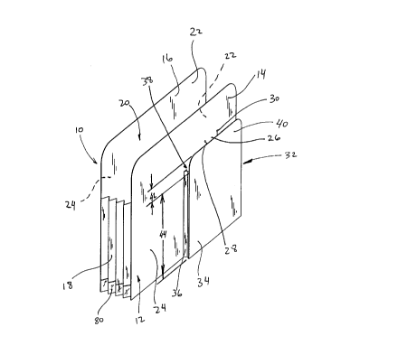
Referring to FIGS. 1 and 2, a preferred embodiment
of the invention is a file 10 with a receptacle 12 with a
front panel 14 and a back panel 16. An expandable receptacle
wall 18 connects the front and back panels 14 and 16. The
receptacle wall 18 extends around the periphery of the left
and right sides of the front and back panels 14 and 16 and of
the bottom thereof. The receptacle wall 18 wall includes
accordion-fold gussets, allowing the front and back panels 14
and 16 to move towards and away from each other.
A large, receptacle compartment 20 open at the top
of the receptacle 12 is thus defined between the front and
back panels 14 and 16 and the receptacle wall 18, and thus
has these panels 14 and 16 and wall 18 as its boundaries.
The front and back panels 14 and 16 have insides 22 facing
into the receptacle compartment 20, and outsides 24 facing
away from the receptacle compartment 20. The front panel 14
is vertically slightly shorter than the back panel 16 so that
labels affixed to the inside of the back panel 16 are visible
over the top of the front panel 14.
The expandable receptacle wall 18 permits the
receptacle compartment 20 to be expanded or contracted
depending on the size of the objects placed therein. Also,
because the edges of the front and back panels 14 and 16 are
only connected to each other through the gussets of the
receptacle wall 18, the front and back panels 14 and 16 can
move with respect to each other while remaining in parallel.
The front panel 14 has a tongue 26, which is
preferably stamped from the front panel 14 during
construction, leaving a slit 28 about the periphery of the _
tongue 26 when the tongue is disposed in a common plane with
the body of the front panel 14. The tongue 26 is protrudable
front the front panel 14 and preferably has a rounded shape.
Rounded holes 30 are made at the base of the tongue, at ends
of the slit 28. Holes 30 relieve stress concentrations at
the edges of the slit 28, reducing the tendency for the front
panel 14 to tear on each side of the tongue 26.
PEDC-125317.1
CA 02275524 1999-06-18
The file l0 also has an expandable utility-pocket
32 on the outside of the receptacle compartment 20. The
pocket is formed by a pocket panel 34 connected to the front
panel 14 by an expandable pocket wall 36, which preferably
comprises an accordion-fold gusset. The pocket wall 36
extends around the periphery of the left and right sides and
the bottom of the pocket panel 34.
A pocket compartment 38 is defined between the
pocket wall 36, the pocket panel 34, and the outside 24 of
the front panel 14. The pocket compartment.38 is open at the
top thereof. The pocket wall 36 allows the pocket panel 34
to move towards and away from the front panel 14 while at
least a portion of the pocket panel 34 remains parallel to
the front panel 14. This permits the pocket 32 to conform to
the size of items of substantially rectangular cross-
sections, such as compact disk covers or small pads or stacks
of paper.
The top of the pocket panel 34 is a flap 40 the
extends upwardly beyond the pocket wall 36 adjacent the open
side of the pocket compartment 38 and is free from the pocket
wall 36. The flap 40 extends beyond the pocket wall 36
preferably by a distance 42, which is at least a fifteenth of
the height 44 of pocket wall 36 on the lateral sides of the
pocket panel 34, and about as long as maximum extension 37 of
the pocket wall 36, as shown in FIG. 5.
The flap 40 is engageable to the front panel 14, as
shown in FIGS. 3 and 4. The tongue 26 and the flap 40 are
engageable to each other with the flap 40 received and
retained between the tongue 26 and the front panel 14. When
the tongue 26 is engaged with the flap 40 as shown, the
pocket compartment 38 is closed, keeping the contents of the
pocket compartment 38 securely therein.
Referring to FIG. 5, the width 46 of the pocket
panel 34 is smaller than the width 48 of the front panel 14.
Consequently, the pocket 32 is better suited to hold smaller
items than the receptacle 12. The width 46 of the pocket
panel 34 is preferably less than about half of the width 48
- 4 - PEDC-125317.1
CA 02275524 1999-06-18
of the front panel 14, with the pocket 32 positioned on the
front panel 14 such that a space 50, at least as wide as the
width 46 of the pocket panel 34, remains on the front panel
14 adjacent the pocket 32. This construction permits similar
files 10 to be stacked front to front and back to back,
without the pockets 32 interfering with each other. Other
arrangements in which facing files have staggered pockets are
also suitable.
Referring to FIG. 6, the file 10 is preferably made
from a strong paperboard material, such as manila or kraft
paper. The pocket panel 34 and pocket wall 36 are preferably
a single piece of paper, and the receptacle wall 18 is also
made from a single piece of paper. The front and back panels
14 and 16 preferably include an inside and an outside sheet
of paper 52 and 54, which are adhered to each other about
edges of the receptacle wall 18. The pocket wall 36 has an
edge 56 adhered to the outside sheet 54 of the front panel
14. The inside sheets 54 are thicker and sturdier than the
outside sheets 52. Preferably, the thick inner sheets 54 are
at least 15 point panels. An acrylic coating is applied to
the paper to render the paper water resistant and wipeable.
The file 10 also has a reinforcing tape 80 that is
adhered to the receptacle wall 18 at the bottom corners
thereof and along the lateral sides thereon. Preferably,
however, the tape 80 does not extend onto the horizontal
bottom 82 of the receptacle wall 18. The tape 80 is a
transparent film, preferably a polyester film, such as
Mylar~, which is sold by Dupont. The tape is preferably
homogenous and does not include fibers therein. The
transparency of the tape 80 makes it substantially invisible
without close inspection, and does not require its color to
be matched to that of the receptacle wall. In addition, it
has been found that polyester tape resists wear better than
fibrous reinforcement materials, such as Tyvek° brand
thermoplastic film.
Referring to FIG. 7, an alternative embodiment of
the invention is a file 58 that has an expandable receptacle
- 5 - ranc-i2s3m .i
CA 02275524 1999-06-18
60 and an expandable utility pocket 62 attached to the
outside of the receptacle 60. A cover 64 is connected to
back panel 66 of the receptacle 60.
Two eyelets 68 are fitted in holes through the
lateral center of the over 64, and an elastic band 70 extends
through the eyelets 68. Ends 72 are spliced together with a
butt splice 74.
As shown in FIG. 8, the cover 64 is positionable
over the open sides of the receptacle 60 and of the pocket 62
in a closed position to close these open sides and positively
retain the contents of both compartments. The elastic band
70 surrounds the file 58, maintaining the cover 64 in the
closed position.
As also shown in FIG. 8, the cover 64 has a
plurality of scores 76 or creases extending substantially in
parallel with the panels 16, 34, and 78 of the file 58.
Creases 76 facilitate and localize bending of the cover 64
around the top of the file 58.
One of ordinary skill in the art can envision
numerous variations and modifications. All of these
modifications are contemplated by the true spirit and scope
of the following claims.
30
6 - PfiDC-125317.1