Note: Descriptions are shown in the official language in which they were submitted.
CA 02334132 2008-08-26
1
METHOD AND APPARATUS FOR AUTOMATICALLY IDENTIFYING SYSTEM
FAULTS IN AN OPTICAL COMMUNICATIONS SYSTEM
FROM REPEATER LOOP GAIN SIGNATURES
Field of the Invention
The present invention relates generally to a line monitoring system employed
in an optical
communications system, and more particularly to a line monitoring system that
automatically
identifies system faults from repeater loop gain signatures.
BackLrround of the Invention
Commercial optical systems use optical fibers to carry large amounts of
multiplexed digital
data over long distances from a transmitting terminal to a receiving terminal.
The maximum
.a: M ~~ ~L-4~L ~~~~ ^~" L~ ~='~~~:x...7 in ~L LL__' ' t___a ~ ~= ~
uaswii~.~, waLuie un~a ~.au uc. uauJUUUCII lu utF tlucr Wiuivut
a~IpliflGatloFl or regeneration Is 11rT11teQ
by the signal loss and dispersion associated with the optical fiber. To
transmit optical signals over
long distances, the lightwave systems normally include a number of repeaters-
periodically located
along the fiber route from the transmitting termirial to the receiving
terminal. Each repeater boosts
the optical input signal to compensate for the transmission losses which
occurred since passing
through the previous repeater. Prior to the widespread availability of
efficient optical
amplifiers, many systems employed repeaters which converted the optical
signals into electrical
signals for amplification by conventional electrical amplifiers. The
ampli.fied electrical signals were
then reconverted to the optical domain, for further transmission along the
optical communication
path. The advent of reliable and low cost optical amplifiers has obviated the
need to convert signals
into the electrical domain for amplification.
Optical amplifiers, such as rare earth doped optical fiber amplifiers, require
a source of
pump energy. In a rare earth doped optical fiber amplifier, for example, a
dedicated pump laser is
coupled to the doped fiber for exciting the active medium (rare earth element)
within the amplifter.
At the same time, a communication signal is passed through the doped fiber.
The doped fiber
exhibits gain at the wavelength of the communication signal, providing the
desired amplification. If
CA 02334132 2000-11-29
WO 00/60773 2 PCT/US00/08675
the optical fiber is doped with erbium, for example, pump energy may be
provided at a wavelength
of 1480 nm or 980 nm, which coincide with the absorption peaks of erbium.
Optical communications systems often employ a line monitoring system (LMS) to
monitor
the performance of the repeaters. The line monitoring system includes line
monitoring equipment
(LME) located in the terminal stations and high-loss loop-back paths (HLLB) in
the repeaters and
terminals. The HLLBs optically couple the two fibers of a fiber pair (one in
each direction of
transmission) such that a very small portion of the optical signal originating
at a transmitting
terminal and being transmitted on one of the fibers of the pair is looped back
and coupled into the
fiber that is transmitting in the reverse direction back toward the sending
terminal. The fundamental
quantity measured by the LME is the round-trip loop gain between the LME and
each terminal and
repeater HLLB on a fiber pair. Through routine analysis of the measured loop
gains, the LMS can
be used to detect changes in the performance of the portion of the system
spanned by the monitored
repeaters and terminals over time. In particular, the analysis may reveal that
these changes may be
due to different causes, such as degradations in pump power, variations in the
loss in the amplifier
output stage, changes in the fiber loss in the transmission span, and
amplifier gain changes, for
example.
To recognize line faults and other problems from the analysis of loop gain
measurernents, as
described herein,, the transmission system must produce a loop gain behavior
under fault and
problem conditions which is significantly different from its normal behavior.
This is clearly the case
under the extreme situations of fiber and/or cable breaks, independent of the
repeater design,
primarily because loop gain measurements beyond the break show that the system
is open (i.e.,
infinite loss). For other more subtle problems, the capability of locating and
identifying the problem
depends strongly on the type of optical amplifiers used in the system. Many
modem repeater designs
employ optical amplifiers which dynamically change their gain to correct for
moderate loss changes
' in the fiber between the repeaters. With such amplifiers, if a loss change
occurs in the fiber between
two repeaters, the loss change is compensated by the aggregate gain changes
that occur in the next
several repeaters, each one compensating for successively smaller portions of
the fiber loss change,
until the entire loss change has been equalized, The larger the loss change to
be compensated, the
more repeaters it takes to equalize the change. The loop gain measurements
through the repeaters
CA 02334132 2000-11-29
WO 00/60773 3 PCTIUSOO/08675
that have adjusted their gains will be different from the loop gain
measurements through the same
repeaters in the nominal case, and it is this difference which can be used to
locate the loss change
and determine its cause. Note that in a system where moderate loss changes are
completely
compensated by the automatic gain change in a single repeater, the measured
loop gain through that
repeater in the increased/decreased fiber loss case is identical to the
measured loop gain through that
repeater in the nominal case. For such situations, the fact that a change in
the fiber loss has occurred
is not detectable by comparison of the measured loop gain data for the two
conditions.
The LMS is used to establish a baseline level of behavior that characterizes
the loop gains in
each fiber pair in the communications system in its normal operating state. By
periodically
monitoring round-trip loop gain changes that occur over time, deviations from
the baseline behavior
can be measured. Deviations from the baseline behavior are referred to as the
signature of the
measurement and are often indicative of a problem or fault in the system.
Extreme faults include
fiber and cable breaks and other problems that result in immediate loss of
service. Other problems
which are also detectable include amplifier power degradations and other loss
variations over time,
which may not have an immediate effect on the quality of service.
The HLLB signature is typically determined from the data shown in FIG. 1(a).
In FIG. 1(a),
the data points represent the values of the measured loop gains for each of
the amplifier pairs in the
sequence in which the amplifier pairs are encountered along the transmission
path. That is, the first
data point represents the loop gain from the LNLE to the first amplifier pair
and the second data
point represents the gain from the LME to the second amplifier pair, and so
on. Curve 10 represents
the baseline behavior and curve 12 represents data obtained during routine
measurement. The
difference between curves 10 and 12, shown in FIG. 1(b), is a visual
representation of the signature
of the gain measurement.
An ideal signature is a straight horizontal line nuining through a gain change
of 0 dB,
indicating that all the loop gain measurements from the amplif er pairs agree
exactly with the pre-
established baseline. Any deviation from such a signature is indicative of
abnormal system
operation, which is caused by a primary (critical) fault that stops
transmission, such as a cable
break, and possibly secondary (non-critical) faults that only degrade system
performance, such as a
decrease in amplifier gain. The particular nature of the fault in the
communications system can often
CA 02334132 2008-08-26
4
be determined from its signature. For example, a failure of one of the pump
lasers driving
an optical amplifier pair is characterized by a gain increase followed by a
gain decrease that
spans approximately six amplifier pairs.
Loop gain signatures are conventionally identified by visual inspection. That
is, the
nature of a fault is determined by visually comparing the measured signatures
against a
series of pre-determined "library" signatures for which faults have been
identified. The
"library" signature that best matches the measured signature presumably
defines the fault.
It would be advantageous to automate the process of identifying system faults
from
their loop gain signatures to assist the system operator in locating line
faults and
degradations which may lead to preemptive repair activity.
Summary of the Invention
Certain exemplary embodiments can provide a method for automatically
identifying
a system fault in an optical communication system that includes first and
second
transmission paths for supporting bidirectional communication, said method
comprising the
steps of: measuring a plurality of optical gain values respectively generated
by a plurality of
optical amplifier units disposed in respective loop back paths extending
through said first
and second transmission paths of the optical communication system; obtaining a
gain
signature by subtracting a plurality of baseline values from the plurality of
optical gain
values; locating directional state changes along said gain signature to
identify a plurality of
directional states; assigning to each of said directional states a pre-
established state such that
said gain signature is represented by a sequence of pre-established states;
comparing said
sequence of pre-established states of said gain signature to a plurality of
pre-determined
sequences of pre-established states, said pre-determined sequences each
corresponding to a
known fault condition; identifying at least one exact match between said
sequence of pre-
established states of said gain signature and said pre-determined sequences,
said matching
pre-determined sequence identifying the system fault that gives rise to said
gain signature.
Certain exemplary embodiments can provide an apparatus for identifying a
system
fault in an optical conununication system that includes first and second
transmission paths
for supporting bidirectional communication, said apparatus comprising: means
for
measuring a plurality of optical gain values respectively generated by a
plurality of optical
amplifier units disposed in respective loop back paths extending through said
first and
CA 02334132 2008-08-26
4a
second transmission paths of the optical communication system; means for
obtaining a gain
signature by subtracting a plurality of baseline values from the plurality of
optical gain
values; means for locating directional state changes along said gain signature
to identify a
plurality of directional states; means for assigning to each of said
directional states a pre-
established state such that said gain signature is represented by a sequence
of pre-
established states; means for comparing said sequence of pre-established
states of said gain
signature to a plurality of pre-determined sequences of pre-established
states, said pre-
determined sequences each corresponding to a known fault condition; means for
identifying
at least one best match between said sequence of pre-established states of
said gain
signature and said pre-determined sequences, said best matching pre-determined
sequence
identifying the system fault that gives rise to said gain signature.
Further embodiments provide a method for automatically identifying a system
fault
in an optical communication system that includes first and second transmission
paths for
supporting bidirectional communication. Measurements are made of a plurality
of optical
gain values respectively generated by a plurality of optical amplifier units
disposed in
respective loop back paths extending through the first and second transmission
paths of the
optical communication system. A gain signature is obtained by subtracting a
plurality of
baseline values from the plurality of optical gain values. Directional state
changes are
located along the gain signature to identify a plurality of directional
states. Each of the
directional states is assigned a pre-established state such that the gain
signature is
represented by a sequence of pre-established states. The sequence of pre-
established states
of said gain signature is compared to a plurality of pre-determined sequences
of pre-
established states. The pre-determined sequences each correspond to a known
fault
condition. At least one exact match is identified between the sequence of pre-
established
states of the gain signature and the pre-determined sequences. The matching
pre-determined
sequence identifies the system fault that gives rise to the gain signature.
Brief Description of the Drawings
FIG. 1(a) shows loop gain measurements obtained from a series of HLLB's that
are
CA 02334132 2000-11-29
WO 00/60773 5 PCTIUSOO/08675
incorporated in optical amplifier pairs arranged in an optical communications
system.
FIG. 1(b) shows the gain signature determined from the measurements shown in
FIG. 1(a).
FIG. 2 shows a simplified schematic diagram of an optical communications
system that
employs repeaters containing optical amplifiers.
FIG. 3 shows a simplified diagram of one of the repeaters shown in FIG. 2.
FIG. 4 shows an exemplary gain signature from which directional states are
obtained.
FIG. 5 shows a table of exemplary predefined directional states that may be
used to
characterize a gain signature.
FIG. 6 is a flowchart of the steps performed in accordance with the present
invention when
defining the pre-established signatures.
FIG. 7 shows a flowchart of the steps performed when comparing a measured
signature
against the pre-established signatures.
Detailed Descrintion
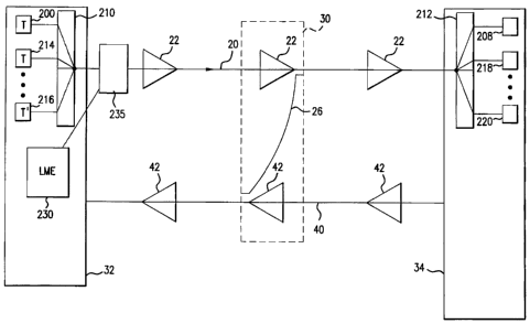
Referring to FIG. 2, there is disclosed a lightwave communications system
which utilizes
optical fiber amplifiers. The system includes transmitter/receiver terminals
32 and 34 and optical
transmission fiber paths 20 and 40 supporting bi-directional communication. A
plurality of optical
amplifiers 22 and 42 are interposed in the fiber paths 20 and 40 between the
transmitter/receiver
terminals 34 and 32. Optical amplifiers 22 and 42 contain a length of doped
fiber that provides a
gain medium, an energy source that pumps the fiber to provide gain, and a
means of coupling the
pump energy into the doped fiber without interfering with the signal being
amplified. These
components of the optical amplifiers are shown in greater detail in FIG. 3.
As shown in FIG. 2 termina132 includes optical communication transmitters 200,
214 and
216 to transmit optical communications channels at wavelength X 1, X2 ... %N,
respectively.
Multiplexer 210 multiplexes these signals together to form a multiplexed
signal that is launched
into optical fiber 20 for transmission to the receiving termina134. At the
receiving terminal 34,
demultiplexer 212 demultiplexes and routes X 1, X2 ... XN to receivers 208,
218 ... 220,
respectively. Of course, in a bidirectional communication system such as shown
in FIG.. 2, both
ternminals 32 and 34 serve as transmitters and receivers and hence, while not
shown in FIG. 2 for
CA 02334132 2008-08-26
6
controller 64, responsive to signals from the receiver 65, applies current to
pump laser
package 60 to adjust the total output power generated by the pump laser
package 60.
As indicated in FIG. 2, the communication system includes a line monitoring
system (LMS) for monitoring the optical path between terminals to determine
the status of
the repeaters. In particular, the LMS determines changes and failures within
each span of
the system, including degradations of pump power, loss in the amplifier output
stage, and
loss in the transmission span.
As previously mentioned, the LMS generates a loop gain signature as shown in
FIG. 1(b). The signature denotes the deviation in system behavior from its
nominal or
baseline performance. While in principle ideal behavior would be represented
by a
measured signature that is a straight horizontal line, in practice, however,
system noise and
other transmission variations will normally occur. As a result, a nominal
signature will
---- -~-- ~- - , ,_,:-1--A .1 '~----r,____,__ ,:-_
'clcllldllõ~',11-QVe a 1Q11U'o111 sllal)G WlUlln sO1llG prG-GJLQU11J11Gu W1nUV
W dUVUI L11G GerV 1111G
defining a nominal band of acceptability. A fault due to a cable break or a
marginally
operating amplifier will produce a signature that has a well defined shape
outside the pre-
established window. Accordingly, it is necessary to account for the nominal
window so
that normal noise-induced drift is not misinterpreted as unacceptable
amplifier operation.
A primary issue that must be addressed in automating the analysis process is
determining an appropriate way to store both the pre-established "library"
signatures and
the measured signatures. In accordance with the present invention, the
"library" signatures
are stored as a series of so-called directional state changes. A single or
"level" signature
state is represented by the portion of the signature extending over two or
more amplifier
pairs (i.e., the data points in FIG. 1(b)), which may fall within the nominal
window. A
transition to another signature state normally arises when the signature
exceeds (above or
below) the nominal window. For example, FIG. 4 shows an illustrative signature
for 10
amplifier pairs in which the nominal window is +/- 0.5 dB.
The 10 data points forming the signature shown in FIG. 4 can be decomposed
into three directional states. The first state is a level state within the
nominal window,
which encompasses points 1-5. The second state may be defined as a rising
state
encompassing points 5-9. It should be noted that successive states may contain
a
common amplifier pair, which is clearly the case for states one and two.
Finally, a third
state may be defined as a falling state that encompasses points 9 and 10. The
transition to
the third state occurs at the point on the curve past point 9 where the 0.5 dB
CA 02334132 2000-11-29
WO 00/60773 7 PCTIUSOO/08675
window is exceeded.
The state structure shown in FIG. 4 can be further refined, if necessary, by
imposing
different windows and different thresholds for the nominal window at different
points along the
signature. In practice, the signature deviations outside the nominal window
are expected to be larger
than the deviations that occur inside the window. This behavior arises because
any motion occurring
outside the window is probably due to a fault, such as a major dB loss that
the amplifiers will try to
correct. In contrast, deviations within the nominal window are likely to be
caused by noise. The
complexity of the states themselves may also be increased, for example, by
distinguishing between
states that undergo a single point rise and those that undergo a multipoint
rise. Such states may be
useful in determining fine system degradations or when analyzing new amplifier
signatures.
FIG. 5 shows six exemplary predefined directional states that may be used to
characterize a
signature. The six states include two initial condition states (states 1 and
2) and four states that
represent basic dynamic states (states 4-6). A signature thus may be defined
by a sequence of the
individual states 1-6. Additional states may be employed by subdividing the
four basic dynamic
states. The additional states may help better differentiate some of types of
faults that occur under
real-world conditions, where more than one fault may occur in a line or where
unexpected signature
variations may arise due to noise. If desired, other states such as
termination states also may be
employed. In general, the states can be easily expanded or modified as
required to remain current
with updated signature detection techniques, to detect new signatures, and
possibly to support new
hardware that exhibits a modified set of signatures.
In principle, a measured signature will most likely exhibit nominal baseline
behavior or a
fully explainable fault condition. Some measured signatures, however, may
exhibit unusual profiles
that represent a series of faults. A series of faults may arise from a primary
fault and one or more
secondary faults that may be byproducts of the primary fault. In some
circumstances it may be
advantageous to filter out the secondary faults from the measured signature so
that the primary fault
can be clearly identified. Some simple filtering techniques that can be
employed including limit
filtering and smoothing filtering. Limit filtering at the floor will limit any
values that are less than
the prescribed floor threshold so that they are equal to the floor value.
Thus, anything at or less than
the floor threshold value will be reduced to the floor value. A similar method
is also used to reduce
CA 02334132 2000-11-29
WO 00/60773 8 PCT/US00/08675
all values within the nominal window to zero, which effectively eliminates
unwanted state changes
within the nominal window.
In smoothing filtering the signature profile is smoothed during rising
segments to eliminate
small random changes that occur within a specified window. The simplified
segment will reduce the
number of directional states that are established for the signature, thus
producing fewer unwanted
secondary fault conditions. Alternatively, a simple curve fitting routine may
be imposed on the
signature to obtain a single rising segment. In practice, the inventors have
found that a series of
alternating linear interpolations is effective to smooth a rising segment,
particularly segments in
which small dB changes frequently occur in a signature representing a break or
other large loss in
dB. Of course other filtering techniques than those previously described may
be employed to
remove the signatures of secondary faults. Generally, however, it is
anticipated that most faults will
be easily recognized without any filtering of secondary faults because of
their unique signatures.
FIG. 6 shows a flowchart of the steps that are performed in accordance with
the present
invention when defining the pre-established signatures. In step 10, a
directional state change table
(DSCT) is generated. The DSCT defines the fundamental directional states such
as shown in FIG. 5.
In step 20, a signature profile table (SPT) is developed. The SPT lists known
system faults and their
pre-established signatures, which are each defined by a different sequence of
the directional states
contained in the DSCT. In step 30, the SPT is electronically stored in a
configuration file so that
signatures may be updated and new signatures added without having to generate
a new executable
code image. This provides the ability to dynamically upgrade the signature
analysis detection
algorithm in the field.
FIG. 7 shows a flowchart of the steps performed when comparing a measured
signature
against the pre-established signatures listed in the SPT. In step 70, the
round trip loop gains from
the repeaters are measured by the LMS and electronically stored. In step 80,
the loop gains are
compared to a pre-established baseline, with the difference between them
defining the measured
signature. In step 82, the signature is scanned from beginning to end and
directional state changes
are located using pre-established windows to account for noise. In step 84,
each distinct directional
state change is assigned one of the fundamental states listed in the DSCT. The
sequence of
measured states defini.ng the measured signature is stored in a signature
state table (SST). In step 86,
CA 02334132 2000-11-29
WO 00/60773 9 PCTIUSOO/08675
the sequence of states in the SST is compared against successive entries in
the SPT until a match is
--found.
The comparison of step 86 may be performed by a modified finite state engine
optimized for
signature analysis. The signature analysis state engine will set pointers to
the beginning of the SST
and the SPT. The state engine will successively compare states from the
initial pointer position of
the SST against the states for the current profile being matched in the SPT.
If an exact match is
found, the profile indication will be stored in the results table and the SPT
pointer wiIl be reset to
the beginning of the SPT and the initial SST pointer position will be reset to
the next state following
the last state of the match. The whole process will be repeated until all
signature states have been
exhausted and all matches in the SST have been found. Thus, the algorithm
detects all possible
fault conditions in the data set that are not overlapping, not just the first
one found. If none of the
SPT profiles match the current SST sequence from the current SST pointer
position, the SST
pointer position will be advanced to the next state and the process continues
as above. Once a match
is found the matching entry in the SST is recorded. The comparison process
continues to determine
if other entries in the SPT match the sequence of states in the SST. If a
match is found to a signature
that corresponds to a fiber or cable break, the comparison process is
discontinued, since the break is
presumably the primary fault in the system and any data points stored after
the break are not
meaningful.
Steps 90 and 92 are to be performed only if secondary faults are to be
filtered. In step 90,
secondary filtering is enabled if the signature is matched to more than a
prescribed number of
entries in the SPT (e.g., 5). Steps 82, 84 and 86 are then repeated to
determine if the filtered
signature now matches a fewer number of the pre-established signatures, which
are represented by
the entries in the SPT. If so, the filtered signature is stored as a sequence
of states in the SST.
Finally, in step 94, the pre-established signatures that have been identified
as matching are reported
to a system operator for further action. Altematively, if the system behavior
is found to be nominal,
this result is reported to the system operator. The report may be displayed on
the graphical user
interface of the LME and/or logged to a history file for subsequent analysis.
In addition, if the LME
has interfaces to higher-level network element managers or other centrally
located operations
centers, the report may also be sent over these interfaces to facilitate
management of the optical
CA 02334132 2000-11-29
WO 00/60773 10 PCTIUSOO/08675
transmission system being monitored by the LME.