Language selection

Search

Patent 2355628 Summary

Third-party information liability

Some of the information on this Web page has been provided by external sources. The Government of Canada is not responsible for the accuracy, reliability or currency of the information supplied by external sources. Users wishing to rely upon this information should consult directly with the source of the information. Content provided by external sources is not subject to official languages, privacy and accessibility requirements.

Claims and Abstract availability

Any discrepancies in the text and image of the Claims and Abstract are due to differing posting times. Text of the Claims and Abstract are posted:

  • At the time the application is open to public inspection;
  • At the time of issue of the patent (grant).
(12) Patent: (11) CA 2355628
(54) English Title: COLLAPSIBLE TIRE STAND
(54) French Title: SUPPORT A PNEUS PLIANT
Status: Expired
Bibliographic Data
(51) International Patent Classification (IPC):
  • B60B 30/00 (2006.01)
(72) Inventors :
  • BELLE, LUCE (Canada)
(73) Owners :
  • BELLE, LUCE (Canada)
(71) Applicants :
  • BELLE, LUCE (Canada)
(74) Agent:
(74) Associate agent:
(45) Issued: 2004-05-11
(22) Filed Date: 2001-08-01
(41) Open to Public Inspection: 2002-05-21
Examination requested: 2001-08-01
Availability of licence: Yes
(25) Language of filing: English

Patent Cooperation Treaty (PCT): No

(30) Application Priority Data:
Application No. Country/Territory Date
60/252,396 United States of America 2000-11-21

Abstracts

English Abstract

A collapsible tire stand is comprised of a frame and said frame preferably made up of a pair of U-shaped members each comprised of a base segment and toward each ends of the base segment extends a supporting member extending perpendicularily therefrom and between each pairs of supporting members are nesting strips into which tires are meant to nest and each of the nesting strips are positioned in pair, one pair being located adjacent the distal tip of the supporting members and a second pair positioned in a spaced relationship proximal to the base segment to allow the tire mounted thereon to remain in a spaced relationship relative to the ground surface.


French Abstract

Support de pneu pliant doté d'une structure constituée de deux membres en forme de U, chacun doté d'un segment de base, un membre de support s'étend à partir de chaque extrémité du segment de base, à la perpendiculaire et des pistes d'imbrication sont situées entre chaque paire de membre de support, dans lesquelles les pneus se fixent, et chaque piste d'imbrication est positionnée par deux paires, une paire est située près de l'extrémité distale des membres de support, et une deuxième paire est située dans un espace proche du segment de base pour permettre au pneu fixé de rester dans un espace proche de la surface du sol.

Claims

Note: Claims are shown in the official language in which they were submitted.


7

CLAIMS

1 A collapsible tire stand comprised of:
a collapsible frame preferably made up of a pair of U-shaped members each
comprised of a base segment;
toward each ends of said base segment extends a supporting member extending
perpendicularly therefrom and between each pairs of said supporting members
are
nesting strips into which tires are meant to nest and each of said nesting
strips being
positioned in pair, one pair of said nesting strip being located adjacent the
distal tip of
said supporting members and a second pair of said nesting strip being
positioned in a
spaced relationship proximal to said base segment so as to allow a tire
mounted
thereon to remain in a spaced relationship relative to the ground surface;
said U-shaped members being pivotally attached together by a pair of hinge
means.

2. A collapsible tire stand as defined in claim 1 wherein:
said nesting strips being pivotally mounted between supporting segments of
said U-
shaped members at predetermined locations and said nesting strips being
configured, sized and positioned so as to be able to receive and support a
conventional pneumatic tire.

3. A collapsible tire stand as defined in claim 1 wherein:
said U-shaped members being mounted so as to be laterally offset relative to
each
other and one of said supporting members being inwardly laterally offset
relative to a


8

longitudinal end of said base segment so as to accommodate an adjacent
supporting
segment of said U-shaped member.

4. A collapsible tire stand as defined in claim 1 wherein:
said hinge means being taken from the group comprised of but not limited to
rivets,
screws, bolts and extending transversally though adjacent supporting segments

5. A collapsible tire stand as defined in claim 1 wherein:
a limiting means for limiting the movement of the U-shaped members to a
predetermined extended configuration connected to and extending between said
base segments.

6. A collapsible tire stand as defined in claim 5 wherein:
said limiting means is taken from the group comprising but not limited to
flexible strip,
band and wire extending between opposed base segments.

7. A collapsible tire stand as defined in claim 3 wherein:
spacing segments providing symmetrical support of the tires in view of said
lateral
offsetting between said U-shaped members.

Description

Note: Descriptions are shown in the official language in which they were submitted.


CA 02355628 2003-09-03
COLLAPSIBLE TIRE STAND
FIELD OF THE INVENTION
The present invention relates to the general field of storage accessories and
is
particularly concerned with a tire stand.
BACKGROUND OF THE INVENTION
There are many situations where it may be desirable to store tires in a
generally
upright configuration. One of such situations relates to the displaying of
tires for retail
sales or the like. Another situation is commonly seen during the changing of
tires of
trucks and cars where it is sometimes desirable to secure the tire in a
proximate and
upright relationship with the car so as to facilitate and expedite the tire
changing
operation.
Still another common situation where it may be desirable to secure the tire in
a
generally upright configuration, relates to the general storage of tires
between
seasons. Indeed, in most areas where seasons bring about different driving
conditions, such as in North America, where so-called winter tires are used
during the
winter to provide a better grip on snow and ice and so-called summer tires are
used
the remainder of the year.
It is often desirable to store the off seasons tires in such a manner that
they occupy

CA 02355628 2003-09-03
2
minimal storage space. Regardless of the reason why the tire must be supported
in a
generally upright condition away from the vehicle, it is also desirable that
the tire be
adequately supported so as to reduce the risk of deforming or otherwise
damaging
the tire.
The prior art offers some examples of structures adapted to secure a tire in a
generally upright position. In general, prior art developments with respect to
such
structures have taken two somewhat different approaches. One approach is
represented by stands which generally grasp a tire or other such article
proximate a
lower portion thereof such as to provide a support proximate a seating surface
for the
article to be supported.
Stands of this type however suffer from numerous drawbacks including the fact
that
they are generally not amenable to the display of articles of different sizes.
Furthermore, the gripping of a tire or other toroidal objects solely about a
lower
portion when in a generally upright position, tends to provide a decided lack
of
stability. The other approach to the supporting of generally toroidal articles
has been
to suspend them in some manner about a hook or other retaining device which is
in
some manner positioned a distance above a floor or other seating surface.
Stand of
this type have generally exhibited a number of problems in commercial
applications.
In order to withstand the weight of certain types of toroidal articles, these
stands have
often employed relatively massive structures which prove to be structurally
cumbersome. In addition, many of these devices are not capable of being
collapsed

CA 02355628 2003-09-03
3
or at least collapsing to an essentially planar form such that temporary
storage or
transposition become significant problems.
In other instances, this type of device has proven to be somewhat unstable due
to the
characteristics of the materials employed in the construction or because of
the
inherent structure of the device.
Accordingly, the various prior approaches to stands for the suspension of
generally
toroidal article has not produced a device which has achieved broad commercial
acceptance. Hence, there exists a need for an improved toroidal article stand.
Advantages of the present invention include the fact that the proposed stand
is
specifically adapted to support a tire or other toroidal articles in a
generally upright
position away from a ground surface. The proposed stand is specifically
designed so
as to support the tire in such a manner as to reduce the risk of altering or
damaging
the said tire.
Furthermore, the proposed stand is designed so as to be relatively stable even
when
the tire is mounted thereon. The proposed stand is further designed so as to
be
collapsible when not in use, thus reducing the need for storage space.
Still further, the proposed stand is particularly well suited to store a pair
of tires in an
overlying relationship relative to each other thus making better use of
storage space.

CA 02355628 2003-09-03
4
The proposed stand is designed to allow for ergonomic installation and
retrieval of the
tires into and out of the stand. Furthermore, the proposed stand is
specifically
designed to be manufacturable using conventional components and conventional
forms of manufacturing in order to provide a toroidal object stand which will
be
economical feasible, long lasting and relatively trouble free in operation.
BRIEF DESCRIPTION OF THE DRAWINGS
An embodiment of the present invention will now be disclosed, by way of
example, in
reference to the following drawings, in which:
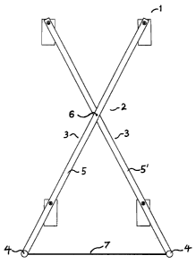
FIG. 1: in an elevational view, illustrates a tire stand in accordance with an
embodiment of the present invention, the tire stand being shown in an
operational
configuration.
FIG. 2: in an elevational view, illustrates a tire stand in accordance with an
embodiment of the present invention, the tire stand being shown in a collapsed
configuration.
FIG. 3: in a side view, illustrates a tire stand in accordance with an
embodiment of the
present invention.
FIG. 4: in a side view, illustrates a tire stand as shown in FIG. 3 with a
pair of
~nventional tires mounted thereon.

CA 02355628 2003-09-03
DETAILED DESCRIPTION
5 FIG. 1: A tire stand 1 has a collapsible frame 2 and said frame 2 is
preferably made
up of a pair of U-shaped members 3 each comprised of a base segment 4 and
toward each ends of the said base segment 4 extends supporting members 5, 5'
extending perpendicularity therefrom. The U-shaped members 3 are mounted so as
to be laterally offset relative to each other and, thus, one of the supporting
members
5' is inwardly laterally offset relative to the longitudinal end of the base
segment 4 so
as to accommodate the adjacent supporting segment 5 of the U-shaped member 3.
Moreover, the U-shaped members 3 are pivotally attached together by a pair of
hinge
means 6 taken from the group comprised of but not limited to rivets, screws,
bolts or
any other suitable means extending transversally though adjacent supporting
segments 5, 5'. The hinge means 6 allows the U-shaped members 3 to pivot
between
their operational extended configuration as shown here and the collapsed
configuration shown in FIG. 2. To limit the movement of the U-shaped members 3
to
a predetermined extended configuration, a limiting means 7 is taken from the
group
comprising but not limited to flexible strip, band or wire extending between
opposed
base segments 4.
FIG. 3: Nesting strips 8 are pivotally mounted behnreen the supporting
segments 5, 5'
of the U-shaped members 3 at predetermined Locations. The nesting strips 8 are
typically configured, sized and positioned so as to be able to receive and
support a
conventional pneumatic tire. Typically, although by no means exclusively, the
nesting

CA 02355628 2003-09-03
6
strips 8 are made out of a suitable polymeric resin such as nylon. The nesting
strips 8
are pivotally attached to the supporting segments 5, 5' by a suitable
pivotable
attachment means 9 taken from the group comprised of but not limited to pins,
rivets,
nuts or screws.
FIG. 4: The pivotal mounting of the nesting strips 9 allow the stand 1 to
accommodate
tires 10 of various diameters while the flexible nature of the nesting strips
9 allows the
said stand 1 to accommodate tires 10 of various widths. Preferably, the
nesting strips
9 are positioned in pair, one pair being located adjacent the distal tip of
the
supporting members 5, 5' while a second pair is positioned in a spaced
relationship
proximal to the base segment 4 to allow the tire 10 mounted thereon to remain
in a
spaced relationship relative to the ground surtace. Preferably, the hinge
means 6 is
located substantially intermediate the first and second nesting strips 8. In
order to
provide for a symmetrical support of the tires 10, in view of the lateral
offsetting
befinreen the U-shaped members 3, spacing segments 11 are preferably mounted
in a
generally perpendicular relationship relative to the supporting members 5, 5'
in order
to compenate for the lateral offsetting.
25

Representative Drawing
A single figure which represents the drawing illustrating the invention.
Administrative Status

For a clearer understanding of the status of the application/patent presented on this page, the site Disclaimer , as well as the definitions for Patent , Administrative Status , Maintenance Fee  and Payment History  should be consulted.

Administrative Status

Title Date
Forecasted Issue Date 2004-05-11
(22) Filed 2001-08-01
Examination Requested 2001-08-01
(41) Open to Public Inspection 2002-05-21
(45) Issued 2004-05-11
Expired 2021-08-03

Abandonment History

There is no abandonment history.

Payment History

Fee Type Anniversary Year Due Date Amount Paid Paid Date
Request for Examination $200.00 2001-08-01
Application Fee $150.00 2001-08-01
Maintenance Fee - Application - New Act 2 2003-08-01 $50.00 2003-05-16
Maintenance Fee - Application - New Act 3 2004-08-02 $50.00 2004-02-13
Final Fee $150.00 2004-02-16
Maintenance Fee - Patent - New Act 4 2005-08-01 $50.00 2005-05-16
Maintenance Fee - Patent - New Act 5 2006-08-01 $100.00 2006-04-05
Maintenance Fee - Patent - New Act 6 2007-08-01 $100.00 2007-07-12
Maintenance Fee - Patent - New Act 7 2008-08-01 $100.00 2008-05-20
Maintenance Fee - Patent - New Act 8 2009-08-03 $100.00 2009-06-29
Maintenance Fee - Patent - New Act 9 2010-08-02 $100.00 2010-07-29
Maintenance Fee - Patent - New Act 10 2011-08-01 $125.00 2011-06-01
Maintenance Fee - Patent - New Act 11 2012-08-01 $125.00 2012-07-23
Maintenance Fee - Patent - New Act 12 2013-08-01 $125.00 2013-07-22
Maintenance Fee - Patent - New Act 13 2014-08-01 $325.00 2015-07-24
Maintenance Fee - Patent - New Act 14 2015-08-03 $125.00 2015-11-12
Expired 2019 - Late payment fee under ss.3.1(1) 2015-11-16 $62.50 2015-11-12
Maintenance Fee - Patent - New Act 15 2016-08-01 $425.00 2017-07-24
Maintenance Fee - Patent - New Act 16 2017-08-01 $225.00 2017-07-24
Maintenance Fee - Patent - New Act 17 2018-08-01 $225.00 2018-07-09
Maintenance Fee - Patent - New Act 18 2019-08-01 $225.00 2019-06-05
Maintenance Fee - Patent - New Act 19 2020-08-03 $225.00 2020-08-03
Owners on Record

Note: Records showing the ownership history in alphabetical order.

Current Owners on Record
BELLE, LUCE
Past Owners on Record
None
Past Owners that do not appear in the "Owners on Record" listing will appear in other documentation within the application.
Documents

To view selected files, please enter reCAPTCHA code :


To view images, click a link in the Document Description column. To download the documents, select one or more checkboxes in the first column and then click the "Download Selected in PDF format (Zip Archive)" or the "Download Selected as Single PDF" button.

List of published and non-published patent-specific documents on the CPD .

If you have any difficulty accessing content, you can call the Client Service Centre at 1-866-997-1936 or send them an e-mail at CIPO Client Service Centre.


Document
Description 
Date
(yyyy-mm-dd) 
Number of pages   Size of Image (KB) 
Cover Page 2002-05-24 1 31
Maintenance Fee Payment 2020-08-03 1 41
Description 2001-08-01 3 208
Representative Drawing 2002-04-24 1 4
Claims 2003-09-03 2 66
Description 2003-09-03 6 219
Claims 2001-08-01 1 62
Abstract 2001-08-01 1 20
Drawings 2001-08-01 2 31
Cover Page 2004-04-14 1 31
Correspondence 2001-09-10 1 9
Assignment 2001-08-01 2 93
Prosecution-Amendment 2003-05-23 2 78
Fees 2003-05-16 3 70
Prosecution-Amendment 2003-09-03 10 334
Fees 2004-02-13 1 25
Correspondence 2004-02-16 2 105
Fees 2007-07-12 2 36
Maintenance Fee Payment 2017-07-24 1 127
Fees 2005-05-16 1 81
Fees 2006-04-05 2 137
Fees 2008-05-20 1 23
Maintenance Fee Payment 2018-07-09 1 51
Fees 2009-06-29 1 241
Fees 2010-07-29 1 19
Fees 2011-06-01 1 237
Maintenance Fee Payment 2019-06-05 1 47
Fees 2012-07-23 1 238
Fees 2013-07-22 1 112
Maintenance Fee Payment 2016-08-17 1 136
Correspondence 2015-12-04 1 30
Maintenance Fee Payment 2015-07-24 1 51
Maintenance Fee Payment 2015-07-30 1 30
Maintenance Fee Correspondence 2015-08-14 1 31
Office Letter 2015-09-22 2 7
Correspondence 2015-09-22 5 105
Maintenance Fee Payment 2015-11-12 1 100