Note: Descriptions are shown in the official language in which they were submitted.
CA 02357606 2001-09-20
LOCK CAP ANCHOR ASSEMBLY FOR ORTHOPAEDIC FIXATION
BACKGROUND
The present invention relates to orthopedic fastening systems and to
mechanisms
for securing and locking a linking or stabilizing element, such as a rod, to a
bone screw
having a slotted head that receives the rod therein. It also relates to
structures or
anchor assemblies having such a slotted or open head for receiving a rod,
wherein the
slotted portion extends from a hook, plate, bracket or positioning arm.
A number of such structures are known. Thus, for example, the widely used
Harms T-plate used for stabilizing the cervical vertebrae has a projecting
slotted bolt
adapted to receive a rod or cable through the slot and clamp down by screwing
a nut
along the bolt to bear down against the rod. Several patents show holding
structures for
a fixation rod that are incorporated in the head of a screw, as in U.S. Patent
5,672,176,
or into a small offset plate which itself may be fastened to the bone, as
shown in
published International Application W096/28105. Other systems involve hooks,
transverse rod connectors, or tandem connectors. Various tools have been
provided for
these systems to enable the surgeon to bend and shape the rod to a desired
contour in
situ, to position the rod in the slot of a bolt or head, and to secure the rod
in position.
Because the rod is the stabilizing member which provides a precise contour,
spacing or connection between one or more vertebrae, bones or bone fragments,
alignment is quite critical, and the ability to pass the rod through two or
more
connecting assemblies requires various actions to form and shape the rod, or
align the
receiving structures at defined positions or path before final clamping is
effected. This
may involve positioning and removing the rod several times to check and adjust
the
degree of alignment. Thus, it is generally desirable to have a closure or
secure locking
mechanism that may be effected with simple installation steps.
One generally accepted locking mechanism simply involves an internally
threaded locking nut that may be tightened down along the axis of the screw or
slotted
shaft, using a tool such as a socket wrench. Another commercial device employs
a
bayonet-mount cap that captures or is captured by the screw head, as in United
States
Patents 5,346,493 and 5,257,993. Another system utilizes a cap element with a
dovetail or dovetail channel that slides over the rod to close the top of the
slot and
-1-
CA 02357606 2001-09-20
wedge the rod firmly in position. This latter construction involves no
rotation of
threaded members, but has the disadvantage that a certain amount of
unobstructed
lateral space along the rod adjacent to the connection point is necessary for
the sliding
installation of the closure cap. Furthermore, the cap inserts or sliding wedge
closures,
while they eliminate the need for awkward screwing or rotational motion during
installation, cannot be used with some existing reduction screws, translation
hooks or
other common hardware having lengthy protruding guide members, reduction tabs
or
the like. Moreover, the wedge/cap closures are a specialized component that
may
require the user to switch entirely over to a proprietary line of orthopaedic
hardware if
he is to utilize the full range of hook, tab, plate and screw fixation points
that may be
required in spinal surgery.
Accordingly, it would be desirable to provide a closure cap for a bone screw
or
similar anchor assembly to secure a fixation linkage such as a rod or cable.
It would further be desirable to provide a rod-securing closure mechanism for
a
screw or anchor that installs simply by a partial turn.
It would further be desirable to provide a rod-securing closure mechanism for
a
screw or anchor that requires minimal lateral clearance along the rod for its
installation.
It would further be desirable to provide a rod securing cap or closure
mechanism
adaptable to diverse reduction screws.
SUMMARY OF THE INVENTION
One or more of these and other desirable traits are achieved in accordance
with
the present invention by a fixation assembly wherein a closure cap fits over
an opening
to close a rod-receiving slot of a fixation screw, hook, post or other anchor
assembly,
and capture the rod therein. A set screw threads through the cap and tightens
against
the rod to further clamp it in the assembly. In one embodiment, the closure
cap extends
over and around the head of the rod-receiving assembly, which may, for example
include a slotted shaft, post or head, and the cap is adapted to lock together
therewith
by limited rotation. This may be accomplished in one embodiment construction
by
arranging the cap to have a set of sector rim protrusions positioned to fit
through a
corresponding set of protruding bosses or partial flange segments located on
the head,
and to rotate into opposition therewith for securing the cap onto the top of
the fixation
-2-
CA 02357606 2001-09-20
screw. The protrusions or flange segments are angled, along the radial
direction, so
that they bear against each other and jam when rotated, thus cannot slip out
of
engagement. The opposed segments tighten and lock the cap against the head
when the
cap is rotated through a partial turn of about twenty-three degrees of arc,
like a
flange-locking bayonet mount. The cap may have a rim that extends over the
outside of
the bolt head to engage external flange segments on the head. In a preferred
embodiment, the mating portions may located internally in the head, with
flange
segments projecting radially inward from the perimeter, and the cap fitting
between
segments in the head of the bolt and locking with a twist-in motion to capture
a rod in
the opening. A hold-down set screw threads through a central opening in the
cap and
tightens down against the rod to clamp the rod firmly in place. The closing
and
clamping may each be effected by a driver tool that operates along the axis of
the
assembly and requires little or no side clearance to rotate either the cap or
the set
screw. In the case of the external, twist-on cap, the limited degree of
rotation allows
the cap to also include slots through the cap to accommodate reduction tabs
extending
upwardly from the underlying screw or anchor member. The quick-twist closure
cap
assemblies of the invention may be adapted to a wide range of screw, hook,
eye, plate,
connector and other anchor assemblies for rod, cable and other linking
elements.
BRIEF DESCRIPTION OF THE DRAWINGS
These and other features of the invention will be understood more fully from
the
description below of representative embodiments thereof taken in conjunction
with
illustrative drawings, wherein
Figures lA-1C schematically illustrate various spinal fixation rod anchor
assemblies of the prior art;
Figure 2 shows on embodiment of an anchor screw of the present invention;
Figures 3 and 3A-3C show views of a closure cap utilized with the anchor screw
of Figure 2 in accordance with the present invention;
Figure 4 shows a second embodiment of an anchor member and closure cap of
the invention;
Figure 4A is a perspective view from below of the cap of Figure 4;
Figure 4B illustrates details of the anchor member of Figure 4;
-3-
CA 02357606 2001-09-20
Figure 5 shows a third embodiment of an anchor member and closure cap of the
invention;
Figures 6A, 6B and 6C illustrate the cap and head structure, respectively, of
embodiment of Figure 5 in greater detail; and
Figures 7A, 7B and 7C illustrate cap, head and assembled structure,
respectively, of another internal twist cap embodiment.
DETAILED DESCRIPTION
The invention and its range of embodiments will be better understood following
a brief description of prior art, illustrating approaches to one- and two-
part anchor
assemblies, as well as certain common constructions.
Figures lA-1C illustrate prior art anchor mechanisms for securing a fixation
rod
as used in spinal fixation. Figure lA illustrates an anchor screw, while
Figure 1B
shows an offset tab having a slotted post for receiving the rod and Figure 1C
shows a
combined system in which anchor screws secure rod-shaped offset elements that,
in
turn, each terminate in an end that grips a common fixation rod. In the anchor
screw of
Figure lA, a screw 1 with a rounded head 2 carries a slotted top member 3 into
which a
rod 5 shown in phantom is clamped by screwing down a threaded press ring or
set
screw 6. The press ring 6 is turned by engagement along its central portion
e.g., by an
Allen wrench, and has external threads 6a which fit corresponding internal
threads 3a of
the top member 3. A separate body 7 fills the space between the inner wall of
the top 3
and the ball head 2 of the screw 1, so that when the rod is pressed down by
the member
6, the screw head is firmly gripped and all parts are rigidly held together.
An external
nut 8 threads over the outside of the top to further strengthen and lock the
assembly.
For this prior art anchor member, the screw l, the press member 6 and the nut
8 may
all be installed with a straight tool, such as an Allen wrench or socket
wrench, inserted
directly along the axis of the screw.
Figure 1B shows another anchor assembly 15 for receiving a fixation rod 5. In
this assembly, an offset tab construction having a body 15a that is anchored
by a
conventional bone screw 10 and including a slotted post (not numbered) for
receiving
the rod, is closed by a cap nut 17 which carries a pressure member 18
centrally thereon
to press down against the rod 5 as the nut is tightened. In each of these two
-4-
CA 02357606 2001-09-20
constructions, the member 6 or 17 for clamping down against the rod 5 installs
by
rotational movement.
Another prior art anchor assembly is illustrated in Figure 1C. In this
article, a
slotted body 21 or 22 is carried either on a bone screw (not visible in the
Figure) or on
a short length of offset rod 22a. In both cases, the slotted body 21 or 22
receives a rod
and clamps it tightly. In this assembly the slotted head member 21 or 22 has
angled or
dovetailed walls at its upper portion, and a correspondingly shaped sliding
cap member
23 is pressed along the dovetail into the upper region, sliding along the axis
of the slot
to close the slot and wedge firmly against the rod passing therethrough. As
noted
above, this construction has a disadvantage that a lateral clearance along the
length of
the rod is necessary for movement of the closure member 23 into position.
Other
constructions are shown in U.S. Patents Nos. 5,346,493, 5,257,993 and
elsewhere.
Thus, the art includes both one-piece, and many-piece anchor assemblies, and
these may look like screws, or may be specialized elements that are themselves
to be
anchored by another assembly. As described further below, the present
invention
provides a closing and fixing mechanism of enhanced utility, with a structure
adaptable
to much of this broad range of hooks, screws, connector assemblies and other
orthopaedic anchor hardware involving one or more rod, cable, wire or other
linking
elements.
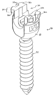
Figure 2 illustrates a first embodiment of an anchor screw assembly 31 of the
present invention. As shown, the anchor screw assembly 31 includes a screw 32
and a
top member 33 which may be integral with the screw or, like the prior art
construction
of Figure lA, may be a separate head member that secures to the proximal end
of the
screw 32. The top member 33 includes a slot indicated generally by 34 for
receiving a
rod, and contains at its uppermost region 35, a plurality of segmented or
partial flange
members 36a, 36b, 36c, 36d which extend radially outward from its perimeter
and have
respective slots or spaces 37a, 37b therebetween. As further shown in Figure
2, each
of the flange segments 36a, 36b..36d has a lower surface 38, as best seen in
the end
views of flange segments 36a and 36c, that engages a closure cap 40 (Figures
3A-3C).
While not shown, one or more of the flange segments or cap may include a
notch,
detent or catch or a jamming feature, to prevent rotation in the opposite
sense.
-5-
CA 02357606 2001-09-20
The anchor screw or hook 31 of Figure 2 is used in conjunction with a closure
cap 40 which is shown in an upward-facing view, from below, in Figure 3C. The
cap
40 fits over and around the upper portion 35 of the slotted, rod receiving top
member.
As shown Figure 3, the cap 40 includes a body 41 having a central threaded
bore 42
extending therethrough and a pair of dependent side members 43a, 43b on
opposed
peripheral sides thereof which extend downward on opposed sides surrounding
the outer
circumference of the top member 33. Each of the side members 43a, 43b carries
mating inwardly directed protrusions 46a, 46b, and 46c, 46d, respectively,
which are
spaced apart and positioned to correspond to the segmented flange members 36a-
36d of
the screw head. In particular, the protrusions 46a to 46d are positioned below
the main
body of the cap 41 by an amount corresponding to the maximum thickness of the
flange
segments 36a to 36d, and are rotationally offset so as to pass down through
the gaps
between segments and rotate into gripping engagement around the segments by a
partial
rotation of the cap 40 about the screw head assembly or top member 33, in the
manner
of a bayonet mounted lid closure. This secures the cap 40 on the top member
closing
the slot to prevent movement of the rod or cable from the head along the axial
direction
of the screw 32. A set screw (not shown) threaded through the aperture 42 is
then
tightened to clamp firmly down against the rod, cable or other linkage
captured in the
slot 34 (Figure 2).
Advantageously, with the foregoing construction, the anchor screw 31 and the
closure assembly 40 as well as the set screw (not illustrated) all install by
simple
rotational movement of a tool that extends directly along the axis of the
screw.
Moreover, as illustrated, the initial locking of the cap on the head assembly
is effected
by a small rotational movement, substantially less than one-half turn, which
corresponds approximately to the length of the lower surface 38 of one flange
segment,
or about 20~ of rotational movement. Thus a very slight movement is sufficient
to
capture the rod 5 (Figures lA-1C) within the slot 34 during initial setup or
fitting of the
fixation rod.
This twist-lock flanged anchoring assembly with a cap structure of the present
invention is readily adapted to diverse other fixation screws of known design,
and thus
in various alternative embodiments and adaptations may carry forward the
advantages
of those other designs. Thus, for example, the locking cap assembly of Figures
2-3 of
-6-
CA 02357606 2001-09-20
the invention may be adapted to an anchor assembly such as a reduction screw,
anchor
screw, or hook in which the anchor member possesses protruding reduction tabs
that
extend upwardly from the head of the anchoring assembly.
Such an embodiment 50 is shown in Figure 4. In this embodiment, the head 53
of the anchor assembly has a pair of reduction tabs 55 extending upwardly from
the
sides of the slot. In this case, the invention contemplates a closure cap 60
with a rim-
engaging securing structure similar to that of cap 40 for engagement by a
small
rotational motion, but the cap structure further includes a pair of arcuate
slots 62a, 62b
located in its central region and sized for passage of the reduction tabs 55
or other
protruding head structure therethrough. Each of the slots 62a, 62b extends
past the
edges of the tabs 55, permitting sufficient rotation of the cap to lock the
cap in position.
The structure of the cap itself strengthens or supports both the surrounding
wall of the
rod receiving slot, and the thin-walled tabs 55 which rise therefrom, while
leaving the
central on-axis region above the cap entirely unobstructed for insertion, for
example, of
a set screw along an axial direction, and permitting line-of sight access by a
driver for
installation.
In any of the foregoing constructions, the rod-receiving head assembly or top
member 33, 53 may be integral with the anchor screw 35, 52 or may be
constituted by
a separate slotted head member that fits about the top of the screw to grip
the rod or
other connecting linkage. Thus, the invention applies to diverse anchors,
hooks,
monoaxial screws, transverse connections or tandem connections, slotted
connectors or
the like.
Figure 4 illustrates this aspect of the invention for a reduction tab
embodiment
of which the head is separate from the screw. As shown, the anchor screw
assembly 50
has a screw body 52 with an enlarged head 54 which may, for example, have an
Allen
or other female socket formed therein (not shown) for applying torque along
the axis of
the screw to insert the screw in bone. A slotted top member 53 having a
tapered
interior bore is first fitted over the head 54, receiving the screw body from
above,
capturing the enlarged ball head 54 of the screw therein. A compressed member
(not
shown) which may be similar to element 7 of Figure lA, may be provided to
create a
binding fit, and this element may be fixed in place, for example, by swaging
at opposed
surface relief drillings 53a, or it may fit by simple compression. The
provision of top
CA 02357606 2001-09-20
member 53 as a separate head structure that is loosely fixed to, but
originally decoupled
from, the screw 52 in this manner allows the slot angle to be set at a later
stage of
installation, while avoiding the risk of losing separate small components.
The cap 60 of this embodiment, which is shown in a perspective view from
below in Figure 4A, is similar to that of the first described embodiment, but
includes
arcuate slots 62a, 62b to accommodate the projecting reduction tabs. In each
case, the
cap member having a dependent locking rim that grips the outside of the
slotted top and
closes the slot by a partial rotation, provides a simple and unobstructed
procedure for
closing the head of the anchor and capturing the rod, cable or other linkage
in the
anchor assembly and clamping the linkage while fixing the orientation.
In each of the foregoing illustrated embodiments, the cap extends radially
beyond the outer radius of the anchor screw head assembly, and has a rim that
extends
to a greater diameter, and slides between the segmented flange bosses 36 to
rotate into
a captured position which closes the slot and captures the rod or other
linkage within
the head of the anchor assembly. A radial slant "RS" may be provided on one or
more
faces of the opposed locking members as shown in the detail Figure 4B to
assure that
they cannot slip radially outward under pressure.
In further embodiments, the invention contemplates a twist-on cap member
which fits within the head of the anchor assembly rather than extending over
and
locking on the outside of the head.
Figure 5 illustrates one embodiment 100 of such a twist-in anchor closing
mechanism. As shown, the anchor assembly 100 has a screw portion 152 for
anchoring in bone, and a head portion 153 for receiving the rod, cable or
other linkage.
A closure cap 140 closes the slotted end of head 153. As in the previously
described
embodiments, the screw and head may be separate assemblies, in which case the
upper
portion of the screw preferably has a ball end as described above that allows
the head
to pivot about the axis of the screw and achieve a further degree of freedom
in angular
orientation before clamping down. As with the earlier described embodiments,
the cap
or closure portion 140 may have a central bore 145 which is internally
threaded to
accommodate a set screw to further clamp the rod in the slot; however, to
simplify the
drawing, threads are omitted from Figure 5.
_g_
CA 02357606 2001-09-20
The internal closure cap 140 has a plurality of radially protruding flange
segments 146, of which one is visible in the Figure, and the cap is pushed
downwardly
on the head so the respective inward and outward directed segments pass
between each
other, in a manner similar to the above-described embodiments. Thus, the
segments
146 fit between corresponding, inwardly protruding segments 158 of the head
153 and
lock thereagainst by a small rotation of the cap 140.
Figures 6A and 6B illustrate the structure of the twist-in cap 140 and the
slotted
head 153 in greater detail.
Figure 6A shows the closure cap 140, and Figure 6B shows the head assembly
153, of an internal closure locking cap of Figure 5. As shown, the head
assembly 153
of the anchor screw has a plurality of internally projecting bosses 158 and
the closure
cap 140 has corresponding outwardly projecting bosses 146. Respective bosses
146,
158 are dimensioned such that the cap 140 may be pushed downwardly between
spaces
of corresponding bosses to position the upper surface 149 of the cap bosses
below the
lower surface 159 of the retaining head bosses 158. As shown in Figure 6A and
6B,
these mating contact surfaces are angled or sloped downwardly toward the
center so
that when the cap 140 is rotated to place opposed bosses in an engagement with
each
other, the cap exerts a net inwardly directed force on the head to prevent
spreading of
the retaining slot. The contours of the sloped ends are relatively sharply
defined,
effectively forming a circumferential ridge 149a, 159a and groove 149b, 159b
on each
of the respective components (Figure 6C). The ridge of one part fits in the
groove of
the other, so that the closure is centered and grips over a substantial
contact area.
As best seen in Figures 5 and 6A, the twist-in cap has opposed edge flats 144
which may provide a contact or engagement surface for a tool such as a wrench
used
for turning the cap upon installation. Each of the flats 144 has a corner to
prevent
over-rotation of the cap, so that upon insertion it rotates to exactly
position the
respective bosses 146, 158 opposite each other as the anchor assembly is
closed. The
set screw is then tightened to secure the fixation linkage captured in the
slot.
Figures 7A-7C illustrate another embodiment of a twist-in closure cap and
spinal
anchor assembly, having an anchor screw, a slotted head and a twist-in closure
cap.
As in the previously described embodiments, the screw and head may be separate
assemblies, e.g., to achieve freedom in angular orientation before clamping
down. The
-9-
CA 02357606 2001-09-20
head and cap structure similarly may be adapted to spinal anchor assemblies of
other
types, such as transverse connectors, anchor plates and other link-receiving
hardware.
As with the earlier described embodiments, the cap may have a central bore
which is
internally threaded to accommodate a clamping set screw to lock and immobilize
the
linkage once it has been captured in the slot; however, to simplify the
drawing, threads
are omitted from Figures 7A and 7C.
In this embodiment, the radially protruding bosses or flange segments 146 of
the
cap, and the inwardly protruding bosses 158 of the head are arranged so the
respective
inward and outward directed segments pass between each other, when the cap is
pushed
downwardly into the head, in a manner similar to the above-described
embodiments.
Thus, the segments 146 fit between corresponding, inwardly protruding segments
158
of the head and lock thereagainst by a small rotation of the cap. In addition,
the twist-
lock mechanism may be configured to exert enhanced contact force in a detent
region
when the clamp screw is tightened down.
As shown in Figures 7A-C, this is achieved in a presently preferred embodiment
by providing lower and upper contact faces 159, 149 on the segments 158, 146
of the
head and cap, respectively, that slope downward toward the center so that when
the set
screw is tightened the upward force on the cap draws the segments 158 inward
and
upward. A vertically-oriented protruding ridge 158a and mating groove 146a are
formed on the head and cap, on or directly above the corresponding flange
region of
each, so that the ridge 158a on the head is urged inwardly against the groove
surface of
the cap. This effectively locks the rotational detent to prevent any
rotational movement
of the cap once the set screw is tightened.
As further seen in Figures 7A and 7C, the twist-in cap has a protruding stop
face 164 that contacts the head and prevents over-rotation of the cap when it
is turned
to close the head. Thus, upon insertion the cap rotates (clockwise as shown)
to
position the bosses 146, 158 exactly opposite each other as the anchor
assembly is
closed. The set screw is then tightened to secure the fixation linkage
captured in the
slot.
-10-
CA 02357606 2001-09-20
The invention being thus disclosed and illustrative embodiments depicted
herein,
further variations and modifications of the invention will occur to those
skilled in the
art. All such variations and modifications are considered to be within the
scope of the
invention, as defined by the claims appended hereto and equivalents thereof.
-11-