Note: Descriptions are shown in the official language in which they were submitted.
CA 02363466 2006-10-23
1
METHOD AND APPARATUS FOR TRANSFERRING INFORMATION
BETWEEN MOBILE TERMINALS AND ENTITIES IN A RADIO ACCESS
NETWORK
FIELD OF THE INVENTION
The present invention finds application to cellular telecommunications
and relates to the transfer of information in a radio access network.
BACKGROUND OF THE INVENTION
A cellular telephone is one example of what is generally characterized
as a "mobile station" (MS), a "mobile terminal" (MT), or even more generally
as
"user equipment" (UE). The term mobile terminal is employed hereafter for
purposes of description. Telecommunications services are provided between a
cellular telecommunications network and a mobile terminal over an air
interface,
e.g., over radio frequencies. An active mobile terminal communicates over the
air
interface with one or more base stations. The base stations are managed by
base
station controllers (BSCs), which in some systems, are known as radio network
controllers (RNCs). The term RNC is employed hereafter for purposes of
description. Radio network controllers are coupled to one or more
telecommunications networks by way of one or more control nodes such as a
mobile
switching center (MSC) node for connecting to connection-oriented, circuit-
switched
networks such as PSTN and/or ISDN, and a general packet radio service (e_g.,
CA 02363466 2001-08-14
WO 00/51374 PCT/SEOO/00338
2
GPRS) node for connecting to connectionless, packet-switched networks such as
the
Internet.
A basic cellular communications system 10 is shown in simplified
function block format in Fig. 1. An example core network 12 is connected to
several
radio network controllers 14 including RNC1, RNC2, and RNC3. Each RNC 14
controls the allocation of radio resources and radio connectivity operations
for a set
of cells: RNC1 controls cells 1:1-1:5, RNC2 controls cells 2:1-2:5, and RNC3
controls cells 3:1-3:5. The RNCs communicate by way of a signaling network,
e.g.,
signaling system number 7 (SS7), and a transport network generally indicated
at 16.
io Each cell is a geographical area where radio coverage is provided by radio
base
station equipment at the base station site. A base station may serve one or
more
cells. A handover occurs as a mobile terminal travels from an old cell to a
new cell.
This permits mobile terminals to "roam" considerable distances. Each cell is
identified using a unique identity broadcast in that cell over a common
broadcast
channel.
As indicated in Fig. 1, the RNCs 14, the interconnecting signaling and
transport network 16, and the radio base station equipment in each of the
cells
together comprise a radio access network (RAN) 20. Mobile terminals (MTs) 18
permit a subscriber access to telecommunications services offered by the core
network 12 via the RAN 20. The radio access network 20 is responsible for the
radio transmission and control of radio connections between the core network
12
and the mobile terminals 18.
In the present invention, different roles are assigned to RNCs in the
RAN depending on circumstances, configurations, etc. One RNC role is that of a
"controlling" RNC (CRNC) which controls the radio resources in its set of
cells. In
the example shown in Fig. 1, the RNC1 is the controlling RNC for cells 1:1 to
1:5,
CA 02363466 2001-08-14
WO 00/51374 PCT/SE0O/00338
3
the RNC2 is the controlling RNC for cells 2:1 to 2:5, and the RNC3 is the
controlling RNC for cells 3:1 to 3:5.
Fig. 2 shows adjacent cells in a cellular communications network. An
active cell denotes the cell currently supporting a radio connection with a
mobile
terminal. Adjacent neighboring cells may be selected by the mobile terminal
via
forward handover to support the connection. Forward handover is a process
where
a mobile terminal itself continues an established connection between a core
network
and the mobile terminal as the mobile terminal moves between different cells
in the
radio access network. Contrasted with traditional handover, the mobile
terminal in
1o forward handover independently re-establishes the radio connection with a
new cell.
This re-establishment of the connection is performed without prior
notification via
the old cell. Nor is there advance preparation in the network to continue the
communication via the new cell. It is the mobile terminal that initiates and
orchestrates forward handover rather than the core network, the core network
node
(e.g., MSC), or the radio access network (RAN).
When the mobile terminal moves between cells controlled by different
RNCs and performs forward handover, other roles are assigned to one or more of
the RNCs for purposes of a connection between the core network and the mobile
terminal. The RNC that controls the cell where the connection to the mobile
terminal is initially established is assigned a "serving" RNC role for the
duration of
the connection. As the mobile terminal moves to new cells, the mobile terminal
may reestablish the connection via a new cell controlled by another RNC which
is
then labeled as a "drift" RNC. For the connection to MT1, the controlling RNC
of
cell 1:2 (i.e., RNC1) acts as the serving RNC. For the connection to MT3, the
controlling RNC of cell 2:5 (i.e., RNC2) acts as the drift RNC. The serving
RNC
role may be re-allocated to another RNC during the connection. The present
invention may also be applied to such re-allocations.
CA 02363466 2001-08-14
WO 00/51374 PCT/SE00/00338
4
A serving RNC (SRNC) has supervisory control of the mobile terminal
connection within the radio access network 20 and provides a single interface
to the
core network 12 for that mobile terminal connection. The role of the drift RNC
is
to support the serving RNC with radio resources for the mobile terminal
connection
in cells controlled by the drift RNC. In the example shown in Fig. 2, RNC1
acts as
the serving RNC for the connections between the core network and mobile
terminals MT1, MT2, and MT3. After forward handovers, the connection to mobile
terminal 3 (MT3) now includes a cell 2:5 that is controlled by RNC2. Thus,
RNC2
functions as a drift RNC for this particular connection.
Referring again to Fig. 1, mobile terminal MT2 is in contact with the
RAN 20 via cell 1:5 having neighbor cells 1:4 and 2:1. As a result of changed
radio
conditions detected from neighboring cell information, MT2 decides, that the
radio
communication is to be reestablished via neighbor cell 2:1 controlled by RNC2
rather than RNC1. Accordingly, signaling and data transport between RNC1 and
RNC2 are required to reestablish the radio connection. RNC1 acts as the
serving
RNC, and RNC2 acts as the drift RNC for MT2's connection. Furthermore, mobile
terminal MT3 is in contact with the RAN 20 via cell 2:5 having neighbor cells
2:4
and cell 3:1. Because of changed radio conditions detected from neighboring
cell
information, MT3 decides that the radio communication is to be re-established
via
cell 3:1 controlled by RNC3. RNC1 acts as the serving RNC, and RNC3 acts as
the
drift RNC for the MT3 connection.
In both of these scenarios, signaling and data transport between serving
RNC and drift RNC are required to re-establish the radio connection. Once a
mobile terminal decides to perform the forward handover, it sends a cell
update
request message to the drift RNC, and the drift RNC sends a cell update
message to
the serving RNC. The serving RNC then returns a cell update accepted message
to
CA 02363466 2001-08-14
WO 00/51374 PCT/SEO0/00338
the drift RNC which passes that message back to the mobile terminal through
the
appropriate cell.
Since forward handover may involve more than one RNC, what is
needed is an efficient way to route control messages and user data from the MT
via
5 the RAN 20 to the core network 12 and vice versa. This requires an efficient
mechanism to route the control and user data between the RNCs in the RAN. Such
efficient communications between RAN nodes or entities are advantageous in
other
scenarios.
One example scenario is found in the context of mobility management,
i.e., messages related to paging and keeping track of the current location of
the
mobile terminal. In packet-switched communication services, radio resources
are
typically shared by plural mobile terminals and used only when either (1) the
mobile
terminal desires to transmit or (2) the network transmits to the mobile
terminal.
When a mobile terminal is connected with the network during a connection
involving a packet-switched service, cell updating and registration area
updating are
employed for mobility management. After an active mobile terminal enters the
coverage area of another cell, the mobile terminal re-establishes the radio
connection
with the new cell by means of a cell update procedure ("cell connected
state").
However, in idle periods of no data transfer, cell updating wastes radio
resources, so registration area (RA) updating is used. In RA updating, the
idle
mobile terminal is in what is referred to hereafter as a "registration area
connected
state." A registration area corresponds to a group of cells Since traffic for
a packet
switched service is "bursty" in nature with long periods of no packet
transfer, radio
resources would be wasted if a radio channel was continuously assigned to a
connection. Therefore, when the mobile terminal in an "RA connected state"
moves
into a new registration area, the mobile terminal updates the network with its
current registration area using a registration area update procedure similar
to the cell
CA 02363466 2001-08-14
WO 00/51374 PCT/SEOO/00338
6
update procedure. Thereafter, the mobile terminal may move freely between
cells
belonging to the same RA without having to perform an update procedure. If a
packet is to be sent from the network to the mobile terminal and the location
of the
mobile terminal is known only at the registration area level (rather than at a
cell
level), a paging message is broadcast in all cells belonging to the
registration area
where the mobile terminal made its last registration area update. When the
mobile
terminal answers the page from the particular cell where it is currently
located, the
mobile terminal enters the "cell connect state." Both cell update related
messages
and registration area update related messages may often require message
routing
io between RNCs in the RAN.
Fig. 3 illustrates an example where cells controlled by RNC1-RNC3 are
grouped into registration areas, RA1-RA6, each consisting of one or several
cells.
Information transmitted on the broadcast channel in each cell may contain cell
and
registration area identifiers for purposes of registration control. As long as
such cell
and registration area identifiers broadcast by a specific cell contain the
same cell and
registration area identifiers assigned to the mobile terminal during the most
recent
cell or RA update procedure, the mobile terminal need not register. However,
when
the terminal mobile terminal does not recognize the broadcast cell and
registration
area identifiers in the cell, it initiates an RA update procedure.
An individual registration area (IRA) for a mobile terminal may be
defined consisting of one or more registration areas (identified by RA
identity)
and/or one or several cells (identified by cell identity). Thus, a mobile
terminal
assigned the IRA of RA4, RA5, and cell 3:4 in Fig. 3, need not perform a new
registration until entering cell 2:2 or 3:5. When there is information to be
sent to a
mobile terminal and the serving RNC must locate the mobile terminal on a cell
level, the serving RNC initiates a paging procedure so that a paging message
is sent in
all cells belonging to the IRA. If the cells of the IRA belong to more than
one RNC,
CA 02363466 2001-08-14
WO 00/51374 PCT/SEOO/00338
7
the serving RNC sends paging request messages directly to each RNC that has a
cell
in the IRA. Alternatively, the serving RNC may send a paging request message
to
each RNC controlling the registration area(s) of the IRA, and to the RNCs
controlling the additional cells of the IRA. The RNCs controlling the
different
registration area(s) will in turn request paging from other RNCs controlling
cells
within the registration areas. The mobile terminal response to the page may be
received in a cell controlled by another RNC than the serving RNC, and
possibly,
by an RNC other than the RNC that acted as the drift RNC at the latest RA
registration.
Accordingly, forward handover and mobile terminal location/mobility
management operations require considerable signaling and data transport in the
radio
access network 20 between RAN entities like RNCs. The RAN also; must keep
track of which RNC controls the cell or registration area where the MT is
currently
known. It would therefore be desirable to have an efficient means to
facilitate
communication/information transfer between RNCs in the RAN that is transparent
outside of the radio access network.
It is an object of the present invention to provide effective and efficient
communication between mobile terminals and entities/nodes in the radio access
network (e.g., RNCs).
It is an object of the present invention to provide and facilitate
addressing of individual nodes in the RAN without each node having to know in
advance the addresses of all other nodes.
It is another object of the present invention to provide and facilitate
addressing nodes in the RAN without a location register common to the RAN
where information related to a connection with a specific mobile terminal is
stored,
CA 02363466 2001-08-14
WO 00/51374 PCT/SEOO/00338
8
e.g., an identity of current cell or registration area, a current serving RNC
address, a
current drift RNC address, a current temporary mobile terminal RAN identifier,
etc.
It is an object of the present invention to provide and facilitate efficient
radio connection re-establishment in a new cell belonging to another RNC than
the
RNC where the radio connection was originally established.
It is an object of the present invention to provide and facilitate efficient
routing of control and user data after radio connection re-establishment in a
new cell
belonging to another RNC than the RNC where the radio connection was
originally
established.
It is an object of the present invention to provide and facilitate efficient
routing of control and user data relating to paging and other mobility
management
messages.
In the context of a cellular communications system that includes a core
network coupled to a radio access network (RAN) and a plurality of mobile
terminals, a connection may be established between the core network and one of
the
plurality of mobile terminals through the radio access network. A temporary
RAN
identifier is associated with the mobile terminal for the established
connection. The
temporary RAN identifier is used to assist in the transfer of information
pertaining
to the established connection or to the establishment of that connection
through the
radio access network. The temporary RAN identifier is included in each data
packet
associated with the connection, and those connection data packets are routed
through the RAN using the temporary RAN identifier incorporated in each
connection packet.
The radio access network includes a first RAN node associated with a
first geographical coverage area and a second RAN node associated with a
second
geographical coverage area. When the mobile terminal moves from the first
coverage
CA 02363466 2001-08-14
WO 00/51374 PCT/SEOO/00338
9
area to the second coverage area, the connection is re-established through the
RAN
by way of the first and second RAN nodes using the temporary RAN identifier.
The temporary RAN identifier employed in packets corresponding to the
established
connection is used to direct those packets to and from the first and second
RAN
nodes. The first and second RAN nodes analyze packets corresponding to the
established connection using a temporary RAN identifier included in each
packet.
From that analysis of the temporary RAN identifier, the first and second RAN
nodes determine where packets are to be routed.
In a preferred example embodiment, the temporary RAN identifier
1o may include (1) a RAN node identifier (the serving RNC identity)
corresponding to
the first radio network controller (RNC) through which the connection was
initially
established and (2) a local mobile terminal identifier unique within this RNC.
The
RAN node identifier and the local mobile terminal identifier are both employed
when making initial contact in a new geographical coverage area. Thereafter,
only a
local mobile terminal identifier, unique within the current controlling RNC,
is
employed in order to save radio resources. Once the established connection is
terminated, use of the temporary RAN identifier is discontinued.
Additional information may be provided along with the temporary
RAN identifier in intra-RAN messages. Such additional information may include
area information that permits the first RNC to route a message for the mobile
terminal to the specific drift RNC controlling the area in which the mobile
terminal
is currently located. Such area information might include a registration area
or a
registration area and an additional cell outside of that registration area.
The
additional information may also include radio condition information.
CA 02363466 2006-10-23
9a
In one aspect, the invention provides in a radio communications system
including a core network coupled to a radio access network (RAN) and a
plurality of
mobile terminals, a method for use after establishing a connection between the
core
network and one of a plurality of mobile terminals through the radio access
network, the
method comprising:
a RAN node associating a temporary RAN identifier with the mobile terminal for
the
connection; and
using the temporary RAN identifier in the RAN to assist in the transfer of
information
through the radio access network relating to the connection.
In one aspect, the invention provides in a radio communications system
including a core network coupled to a radio access network (RAN) and a
plurality of
mobile terminals where a connection between the core network and one of a
plurality of
mobile terminals located in a first geographical area may be established
through the radio
access network, a method comprising:
associating a first RAN identifier with the one mobile terminal for the
connection to be
established;
using the first RAN identifier to assist in handling the connection in the
radio access
network when the one mobile terminal initially communicates with the radio
access
network from a second geographical area; and
using a second RAN identifier to assist in handling the connection in the
radio access
network after the initial communication by the one mobile terminal from the
second
geographical area.
In one aspect, the invention provides in a radio communications system
including a core network coupled to a radio access network (RAN) including a
first
Radio Network Controller (RNC) associated with a first area and a second Radio
Network Controller (RNC) associated with a second area and a plurality of
mobile
terminals, where a connection maybe established between the core network and
one of a
plurality of mobile terminals located in the first area through the radio
access network
using the first RNC, a method comprising:
the first RNC associating a temporary RAN identifier with the one mobile
terminal for
the connection; and
CA 02363466 2006-10-23
9b
when the mobile terminal re-establishes the connection with the second RNC,
the first
RNC communicates information associated with the connection with the second
RNC
using the temporary RAN identifier.
In one aspect, the invention provides for use in a radio communications
system including a core network coupled to a radio access network (RAN) and a
plurality
of mobile terminals, a RAN node comprising:
a memory having at least one region for storing computer executable program
code; and
a processor for executing the program code stored in the memory,
wherein the program code includes code responsive to a request to communicate
with or
by one of the mobile terminals to establish a connection between the core
network and
the one mobile terminal through the radio access network and to associate a
temporary
RAN identifier for the connection; and code responsive to a message from the
core
network that uses the temporary RAN identifier to assist in a transfer of
information in
the radio access network.
In one aspect, the invention provides for use in a radio communications
system including a core network coupled to a radio access network (RAN) and a
plurality
of mobile terminals, where a connection may be established between the core
network
and one of a plurality of mobile terminals through the radio access network,
an apparatus
comprising:
means in the RAN for associating a temporary RAN identifier with the mobile
terminal
for the established connection; and
means in the RAN for using the temporary RAN identifier in the RAN to assist
in the
transfer of information through the radio access network.
In one aspect, the invention provides in a radio communications system
including a core network coupled to a radio access network (RAN) including a
first
Radio Network Controller (RNC) associated with a first area and a second Radio
Network Controller (RNC) associated with a second area and a plurality of
mobile
terminals, where a connection may be established between the core network and
one of a
plurality of mobile terminals located in the first area through the radio
access network
using the first RNC, a method comprising:
CA 02363466 2011-04-18
9c
the first RNC assigning a temporary RAN identifier and a first
RNC mobile terminal identifier (MT ID) to the one mobile terminal
for the connection;
sending control or user data between the mobile terminal and the
first RNC using the first RNC MT ID;
if the mobile terminal re-establishes the connection with the
second RNC, the first RNC communicates information associated
with the connection with the second RNC using the temporary RAN
identifier;
the second RNC assigning a second RNC MT ID to the mobile
terminal;
and sending control-or user data between the mobile terminal and
the first and second RNCs using the second RNC MT 1D.
According to an aspect of the present invention there is provided
a method for use in a radio communications system including a
core network coupled to a radio access network (RAN) and a
plurality of mobile terminals, where a connection is established
between the core network and one of a plurality of mobile
terminals through the radio access network, the radio access
network includes a Initial RAN node associated with a first
geographical coverage area and a second node associated with a
second geographical coverage area, the method comprising the
steps of:
associating, in the Initial RAN node, a temporary RAN
identifier with the mobile terminal for the connection;
using the temporary RAN identifier in the RAN to assist in
transfer of information through the radio access network relating
to the connection; and
using the temporary RAN identifier for re-establishing the
connection when the mobile terminal is moving from the first
coverage area to the second coverage area.
CA 02363466 2011-04-18
9d
According to another aspect of the present invention there is
provided for use in a radio communications system including a
core network coupled to a radio access network (RAN) and a
plurality of mobile terminals, where a connection may be
established between the core network and one of the plurality of
mobile terminals through the radio access network, apparatus
comprising:
means in the RAN for associating a temporary RAN identifier
with the mobile terminal for the established connection;
means for using the temporary RAN identifier in the RAN to
assist in the transfer of information through the radio access
network, wherein the radio access network includes an Initial RAN
node associated with a first geographical coverage area and a
second node that currently serves the mobile terminal, which
second node is associated with a second geographical coverage
area;
the apparatus further comprising means for using the
temporary identifier in packets corresponding to the established
connection to direct those packets to the initial RAN node; and
wherein the mobile terminal moving from the first coverage
area to the second coverage area is arranged to reestablish the
connection using the temporary RAN identifier.
WO 00/51374 PCT/SE0O/00338
BRIEF DESCRIPTION OF THE DRAWINGS
The foregoing and other objects, features, and advantages of the
invention will be apparent from the following description of preferred example
embodiments as illustrated in the accompanying drawings in which reference
5 characters refer to the same parts throughout the various views. The
drawings are
not necessarily to scale, emphasis instead being placed upon illustrating the
principles
of the invention.
Fig. 1 is a function block diagram of a radio communications system in
which an example embodiment of the present invention may be employed;
10 Fig. 2 is a diagram illustrating conceptually a cellular network
identifying an active cell surrounded by neighboring cells; ,
Fig. 3 illustrates a portion of the radio communications network shown
in Fig. 1 and also illustrates the concept of registration areas;
Fig. 4 is a flowchart diagram illustrating an example embodiment of the
present invention;
Fig. 5 is a flowchart diagram illustrating another example embodiment
of the present invention;
Fig. 6A is a signaling diagram showing example messages
communicated between RAN entities in Fig. 1;
Fig. 6B illustrates example formats of the messages employed in
Fig. 6A;
Fig. 7A is an example signaling flow diagram of a cell update procedure;
Fig. 7B illustrates example formats of messages shown in Fig. 7A;
CA 02363466 2001-08-14
CA 02363466 2001-08-14
WO 00/51374 PCT/SEOO/00338
11
Fig. 8A is a signaling diagram of a cell update request that involves both
a serving RNC and a drift RNC;
Fig. 8B shows example formats of messages employed in Fig. 8A;
Fig. 9A is a Change of State signaling flow diagram;
Fig. 9B shows example formats of messages employed in Fig. 9A;
Fig. 10A is a signaling flow diagram of a paging operation; and
Fig. 10B illustrates example message formats of the messages employed
in Fig. 10A.
DETAILED DESCRIPTION OF THE DRAWINGS
In the following description, for purposes of explanation and not
limitation, specific details are set forth, such as particular embodiments,
data flows,
signaling implementations, protocols, techniques, etc., in order to provide an
understanding of the present invention. However, it will be apparent to one
skilled
in the art that the present invention may be practiced in other embodiments
that
depart from these specific details. In other instances, detailed descriptions
of well-
known methods, interfaces, devices, and signaling techniques are omitted so as
not to
obscure the description of the present invention with unnecessary detail.
The present invention may be implemented in the example cellular
communications network illustrated in Figs. 1-3 and described above. Of
course,
those skilled in the art will appreciate that the present application can be
employed
in other contexts as well.
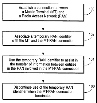
Fig. 4 illustrates an example embodiment of the present invention.
Initially, a connection is to be established between a mobile terminal (MT)
and a
radio access network (RAN) (block 100). A temporary RAN identifier is
associated
CA 02363466 2001-08-14
WO 00/51374 PCT/SEOO/00338
12
by the RNC through which the connection is initially established, i.e., a
serving
RNC. That temporary RAN identifier is further associated with the mobile
terminal, and as a result, identifies the specific RAN connection (block 102).
The
temporary RAN identifier is then used to assist in the transfer of information
between entities in the RAN that are involved with the MT-RAN connection as
well
as between the MT and the RAN (block 104). This would include both information
that is used in establishing the connection, in maintaining that connection,
and in
transferring that connection between different cells as the mobile terminal
moves.
Use of the temporary RAN identifier is discontinued when the MT-RAN
connection terminates.
Fig. 5 shows another more elaborate -- but still example --embodiment
of the present invention. An MT-RAN connection is established via, a serving
RNC
(SRNC) (block 110) between the core network 20 and one of the mobile
terminals 18. For purposes of illustration, the serving RNC corresponds to
RNC1
in Fig. 1, assuming that RNC1 is the controlling RNC (CRNC) for the cell where
the MT-RAN connection is established. The SRNC assigns a temporary RAN ID
and a CRNC MT ID to the MT to identify the MT-RAN connection (block 112).
Because the radio interface portion of the connection involves only the CRNC
and
the MT, only the CRNC MT ID need be used. Therefore, only the CRNC MT ID
is inserted into control and user data packets transported over the radio
interface
associated with the MT-RAN connection (block 114). The temporary RAN ID
consists of one part that identifies the SRNC (an SRNC identifier or address)
and
one part that identifies the mobile terminal within the SRNC (an SRNC MT
identifier). The CRNC MT ID is typically shorter than the temporary RAN ID in
order to minimize addressing information length over the radio interface. The
use of
two identifiers -- SRNC MT ID and CRNC MT ID -- is particularly beneficial in
a
later cell update procedure conducted at a cell controlled by another RNC.
While
the SRNC MT ID should preferably be allocated by the SNRC, the CRNC MT ID
CA 02363466 2001-08-14
WO 00/51374 PCT/SEOO/00338
13
may be allocated by a DRNC to avoid collisions. When the CRNC controlling the
cell of the MT is also the SRNC, the SRNC MT ID and the CRNC MT ID may be
the same.
When the MT re-establishes the MT-RAN connection via a new cell
controlled by the same RNC, now acting as the SRNC, the temporary RAN ID is
used to effect the re-establishment (block 116) because the MT is not aware
whether
the new cell is controlled by the same or another RNC. The SRNC may optionally
assign a new CRNC MT ID to the MT (block 118) to be inserted in each control
and
user data packet sent over the radio interface on the MT-RAN connection
(block 120). Of course, the use of the same CRNC MT ID assigned in block 112
may also be continued.
When the MT re-establishes the MT-RAN connection via a new cell
controlled by a new RNC, acting as the DRNC for the MT-RAN connection, the
temporary RAN ID is again used to establish the connection in the new cell
(block 122) because the MT is not aware that the new cell is controlled by
another
RNC. The DRNC assigns a new CRNC MT ID to the MT (block 124) to be
inserted in each control and user data packet sent over the radio interface on
the MT-
RAN connection (block 126).
Optionally, if the MT-RAN connection is converted from a packet
type connection to a dedicated type of connection through the RAN 20, the use
of
the temporary RAN ID for identification of packets in the radio interface is
discontinued because the channel is then dedicated to just that connection
(block 128). There is no longer a need to route/address packets. However, if
the
MT-RAN connection is later re-converted to a packet-type of connection, use of
the
previous temporary RAN ID may be resumed or a new temporary RAN ID be
assigned by the SRNC. In any event, when the MT-RAN connection is terminated,
use of the temporary RAN ID is discontinued (block 130).
CA 02363466 2001-08-14
WO 00/51374 PCT/SEOO/00338
14
A specific example relating to establishing a MT-RAN connection is
now described in conjunction with the cellular system 10 shown in Figs. 1 and
3, the
signal flow shown in Fig. 6A, and the packet formats shown in Fig. 6B. When
the
MT1 initially establishes a connection with the RNC1 by way of cell 1:2, the
RNC1
acts as the serving RNC for that MT-RAN connection. The Connection Request
message (1) is sent from MT1 to the SRNC as shown in Fig. 6B. Also included
is, for
example, a random ID (unrelated to the invention) used to avoid collisions in
random access attempts over a random access channel. The SRNC then sends a
Connection Accept message (2) to the MT1 which, as shown in Fig. 6B, includes
a
io temporary RAN ID. Because this is an initial connection establishment
request, the
temporary RAN ID preferably includes in this example embodiment both an SRNC
ID as well as a MT identifier recognized by the SRNC (i.e., an SRNC MT ID).
Both
IDs are used to establish routing through the RAN and to identify the MT-RAN
connection when the MT moves outside the area covered by cells controlled by
the
SRNC, particularly when the connection is re-established in a cell not
controlled by
the SRNC. Because RNC1, now acting as SRNC for the MT-RAN connection, is
also the CRNC for cell 2:1, the RNC1 also assigns a CRNC ID to the MT (i.e., a
CRNC MT ID). In this single RNC example, the SRNC MT ID could be adopted as
the CRNC MT ID.
At this stage, control and user data messages can be exchanged between
the MT and core network via the SRNC. Control messages might relate for
example
to authentication and service negotiation, the details of which are not
relevant to the
present invention. Example formats of control and user data messages
transferred
between the SRNC and MT are illustrated at messages (3) and (4) in Fig. 6B and
employ only the CRNC MT ID.
The CRNC MT ID is preferably used as the address for messages (3)
and (4) because it is shorter than the temporary RAN ID and therefore uses
less radio
WO 00/51374 PCT/SEOO/00338
resources. It is also used because the longer temporary RAN ID is not
necessary
after the routing path between the SRNC and MT is initially established by the
message (2). However, the longer temporary RAN ID could be used as the address
for messages (3) and (4). Once the RNC1 recognizes that it is the serving RNC,
it
5 functions as the direct interface to the core network and to the mobile
terminal for
that connection.
Figs. 7A and 7B illustrate a signaling diagram and example message
formats, respectively, for a cell update procedure when the mobile terminal
MT1
moves from cell 1:2 to cell 1:3. Having entered into a new cell, the mobile
terminal
io MT1 must register in the new cell, and therefore, sends a Cell Update
Request
message (1) to the serving RNC (RNC1). The form of the Cell Update Request
message (1) shown in Fig. 7B includes, in addition to the substantive message,
the
temporary RAN ID (including the SRNC ID and SRNC MT ID). The longer
temporary RAN ID is needed because the MT does not know which RNC controls
15 the cell where the MT performed the cell update. The SRNC then sends a Cell
Update Message (2) to the mobile terminal having a format corresponding to
that
shown in Fig. 7B. Specifically, a new CRNC MT ID is assigned by the CRNC
controlling the cell where the MT made the cell update. Alternatively, the
SRNC
MT ID assigned when the connection was initially established via cell 1:2 may
also
be employed as the CRNC MT ID since the RNC controlling the cell is the SRNC.
Still further, the same CRNC MT ID assigned in a previous cell may be used.
Information transfers using message formats (3)-(5) continue with preferably
only the
shorter CRNC MT ID included for addressing/routing with the control or user
data
in each packet.
A further example implementation of the present invention is now
described in conjunction with Figs. 8A and 8B which illustrate a signaling
diagram
and example message formats, respectively, for a more complicated cell update
CA 02363466 2001-08-14
CA 02363466 2001-08-14
WO 00/51374 PCT/SEOO/00338
16
procedure. The mobile terminal MT1 moves from cell 1:5 and enters cell 2:1.
Cell 2:1 is controlled by a new RNC (RNC2). The mobile terminal MT1 sends a
Cell Update Request message (1) to the drift RNC (RNC2) using the message
format
shown in Fig. 8B at (1). The temporary RAN identifier (ID) accompanying the
Cell
Update Request includes both the SRNC ID and the SRNC MT ID address
information. The drift RNC (DRNC) allocates a new CRNC MT ID. Using the
SRNC ID included the temporary RAN ID, the drift RNC (RNC2) determines the
SRNC address and forwards to the SRNC the Cell Update Request message along
with the SRNC MT ID, the DRNC address, the DRNC ID, possibly a new CRNC
io MT ID, and new cell information (e.g., cell identification of the new cell
so that the
SRNC knows this information). The SRNC analyzes the Cell Update Request
message (2) and employs the DRNC address and CRNC MT ID to route the Cell
Update Accept message (3) back to the appropriate drift RNC (i.e., RNC2).
Message 3 also contains the old CRNC MT ID (if any is allocated by this DRNC)
in
order to de-allocate this identification number with the DRNC. If a third RNC
is
involved, (e.g., the mobile terminal moves from a cell under the control of
RNC2 to
a cell under the control of RNC3), while the RNC1 is the serving RNC, a
specific
message may be employed to release the CRNC MT ID at the "old" drift RNC
(RNC2).
The drift RNC sends a Cell Update Accept message (4) to the MT 1
coupled with the temporary RAN ID (SRNC ID and SRNC MT ID) and the new
CRNC MT ID to be used for subsequent data transfers within the same cell. The
mobile terminal acknowledges the assignment of the CRNC MT ID by sending a
"Cell Update Confirm" message (5) to the drift RNC. The drift RNC forwards
this
message to the serving RNC along with the SRNC address and the SRNC MT ID as
shown at (6).
WO 00/51374 PCT/SEOO/00338
17
Subsequent data messages are passed between the MT1 and the core
network (CN) by way of the drift RNC and the serving RNC in messages (7)-(10).
In the direction from the MT1 to the SRNC, the message (7) is routed to the
drift
RNC where the mobile terminal is currently located. The DRNC ID is used as the
RAN address of RNC2 or as a means to derive the RAN address of RNC2. The
CRNC MT ID is used to identify the MT1 within the drift RNC (RNC2). The drift
RNC forwards the message to the mobile terminal at (8) using the CRNC MT ID as
the mobile terminal identifier. In the uplink direction towards the RAN, the
mobile
terminal uses the CRNC MT ID identifier in the message (9). The drift RNC
io forwards the message (10) to the serving RNC routing it through the RAN
using the
serving RNC ID as its RAN address or as a means to derive the RAN address of
the
serving RNC. The serving RNC MT ID is used to identify the mobile terminal by
the serving RNC. The serving RNC also uses the SRNC MT ID to identify the
corresponding user and forward the message to the core network.
Yet another example scenario where this more detailed example
embodiment of the invention may be employed is described in conjunction with
Figs. 9A and 9B. At periods with very low traffic involving the mobile
terminal, the
SRNC may lower the activity level of the mobile terminal MT1 so that it needs
only
register/update with the RAN from its current location when passing a
registration
area border thereby conserving radio resources (see the example registration
areas
illustrated in Fig. 3). The SRNC decides to change the activity level of the
mobile
terminal MT1 to "RA state." The SRNC sends the message (1) "Change to RA
State" to the drift RNC using the CRNC MT ID (as previously allocated by the
drift
RNC) to identify the mobile terminal MT1. This message may optionally contain
cell information that specifies the area (in terms of cell and/or RA
identities) where
the mobile terminal MT1 may move without having to update its location. This
area is referred to as the Individual Registration Area (IRA) for this MT. If
not
included in the message, the MT receives the valid registration area
information from
CA 02363466 2001-08-14
CA 02363466 2001-08-14
WO 00/51374 PCT/SEOO/00338
18
the broadcast channel of the cell. The drift RNC forwards the message to the
mobile
terminal using the CRNC MT ID as an address. The mobile terminal acknowledges
the reception of the message by sending a "Change to RA State Accept" message
to
the drift RNC. Thereafter, the drift RNC forwards this message to the serving
RNC
using the SRNC address. The SRNC MT ID is used to identify the mobile terminal
within the SRNC.
To avoid having to store information about all registration areas and
the RNCs that control the cells of those registration areas in every RNC of
the
RAN, the SRNC may, prior to sending message (1) in Fig. 9B, selectively
request this
1o information from the drift RNC. The drift RNC selects the appropriate area
for the
mobile terminal, (in terms of registration areas and/or cells), and returns
this
information to the serving RNC together with the RNC identities and the RNC
addresses of the RNCs that control the cells of that area.
Irrespective of the mobile terminal's activity level, the SRNC needs to
be able to locate the idle mobile terminal at a cell level whenever there is
data to be
sent to that mobile terminal. The SRNC sends requests for paging to each RNC
controlling cells of the IRA. Figs. 10A and 10B illustrate an example paging
procedure where this more detailed example embodiment of the invention may be
employed. A paging request (1) is sent from the serving RNC (e.g. RNCZ) to
other
RNCs (RNC2 and RNC) which control cells of the MT's IRA. As shown in
Fig. 10B, the page request includes the address of one of the appropriate
other RNCs
(RNCZ or RNC3) along with the SRNC ID and the SRNC MT ID. Both of the
other RNCs that receive the page request from the serving RNC send out paging
messages (2) to each of the cells controlled by that RNC that also include the
SRNC
ID and the SRNC MT ID. These broadcast Paging messages (2) include the SRNC
ID and the MT ID. The Paging Response (3) from the mobile terminal from one of
the cells controlled by RNC3 (in this example) is received. The drift RNC
CA 02363466 2001-08-14
WO 00/51374 PCT/SEOO/00338
19
(corresponding to RNC3) sends a Paging Response message (4) back to the
serving
RNC which includes the SRNC address, the SRNC MT ID, the paging response
message itself, the drift RNC3 address, the CRNC MT ID newly allocated by
RNC3,
and cell and neighboring cell information. The serving RNC sends a Connection
Accept message (5) to the drift RNC containing the RNC3 address and the CRNC
MT ID. The drift RNC (RNC3) sends a Connection Accept message (5) back to the
mobile terminal which includes the SRNC ID, the SRNC MT ID, the RNCZ CRNC
MT ID, along with the message. Accordingly, control and user data can be
transported between the SRNC and the mobile terminal via the DRNC (RNC2)
using message formats similar to those shown in messages (7)-(10) in Fig. 8B.
The present invention provides for efficient and dynamic exchange of
address/routing information between a mobile terminal and nodes (e.g., RNCs)
in
the radio access network. This is particularly advantageous when the mobile
terminal re-establishes its connection with the radio access network using
forward
handover. The mobile terminal can re-establish the connection via a cell
controlled
by any RNC within the RAN, control messages can be routed between RNCs
within the RAN in order to update the serving RNC with the current location
(i.e.,
cell and controlling RNC) of the mobile terminal, and control and user data
can be
efficiently routed between the core network and the mobile terminal by way of
the
RAN. The efficient addressing and routing scheme of the invention is also
advantageous when an idle mobile terminal communicates its current location or
when the idle mobile terminal needs to be located.
While the present invention has been described with respect to a
particular embodiment, those skilled in the art will recognize that the
present
invention is not limited to the specific embodiments described and illustrated
herein.
Different formats, embodiments, and adaptations besides those shown and
described
as well as many modifications, variations, and equivalent arrangements may
also be
CA 02363466 2001-08-14
WO 00/51374 PCT/SEOO/00338
used to implement the invention. Therefore, while the present invention has
been
described in relation to preferred example embodiments, it is to be understood
that
this disclosure is only illustrative and exemplary of the present invention.