Note: Descriptions are shown in the official language in which they were submitted.
CA 02386988 2002-05-16
Virtual Steering of Induction Tool Attenuation and Phase Difference
Measurements
BACKGROUND
Field of the Invention
[01 ] The present invention generally relates to the measurement of properties
of earth
formations. More particularly, the present invention relates to a method for
virtual steering of
induction tool measurements to determine formation properties such as dip
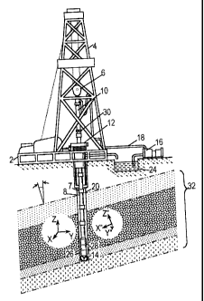
angle and formation
resistivity.
Description of the Related Art
[02] The basic principles and techniques for electromagnetic logging for earth
formations are
well known. Induction logging to determine the resistivity (or its inverse,
conductivity) of earth
formations adjacent a borehole, for example, has long been a standard and
important technique
in the search for and recovery of subterranean petroleum deposits. In brief,
the measurements
are made by inducing electrical eddy currents to flow in the formations in
response to an AC
transmitter signal, and measuring the appropriate characteristics of a
receiver signal generated
by the formation eddy currents. The formation properties identified by these
signals are then
recorded in a log at the surface as a function of the depth of the tool in the
borehole.
[03] Subterranean formations of interest for oil well drilling typically exist
in the form of a
series relatively thin beds each having different lithological
characteristics, and hence, different
resistivities. Induction logging is generally intended to identify the
resistivity of the various
beds. However, it may also be used to measure formation "dip".
-1-
CA 02386988 2004-12-08
[04] Wellbores are generally not perpendicular to formation beds. The angle
between the
axis of the wellbore and the orientation of the formation beds (as represented
by the normal
vector) has two components. These components are the dip angle and the strike
angle. The dip
angle is the angle between the wellbore axis and the normal vector for the
formation bed. The
strike angle is the direction in which the wellbore axis "leans away from" the
normal vector.
These will be defined more rigorously in the detailed description.
[05] The determination of the dip angle along the length of the well plays an
important role
in the evaluation of potential hydrocarbon reservoirs and in the
identification of geological
structures in the vicinity of the well. Such structural and stratigraphic
information is crucial for
the exploration, production, and development of a reservoir. Further, the dip
angle
determination may be used to compensate for boundary effects on the
resistivity measurements.
See Gianzero, U.S. Patent No. 5,757,191, filed Dec. 9, 1994.
[06] An induction dipmeter was first suggested by Moran and Gianzero in
"Effects of
Formation Anisotropy on Resistivity Logging Measurements" Geophysics, Vol. 44,
No. 7, p.
1266 ( 1979). A pulsed electromagnetic dipmeter with spatially separated coils
was proposed by Gianzero and Su in U.S. Patent No. 5,115,198, filed September
1989.
[07] The above dipmeters employ multi-axial transmitter and receiver "triads".
Transmitter-
receiver coupling measurements may be made along each axis and between axes as
well.
Because the principle of linear superposition applies to electromagnetic
fields, rotational
transforms can be used to manipulate the coupling measurements. The
measurements of
-2-
CA 02386988 2002-05-16
"virtual" transmitters and receivers having arbitrary orientations can be
synthesized in this
manner.
[08] However, the most reliable induction tools are not configured to measure
transmitter-
receiver couplings. Rather, they are configured to make inherently compensated
measurements
of signal attenuation and phase difference between a pair of receiver coils.
Unfortunately linear
superposition does not apply for signal attenuation and phase differences, so
the measurements
of these tools cannot be manipulated using existing techniques.
SUMMARY OF THE INVENTION
[09] Accordingly, there is disclosed herein an apparatus and method that
provide steerable
measurements of attenuation and phase difference. In a preferred embodiment, a
logging tool is
provided with two triads of orthogonal receivers and a triad of orthogonal
transmitters. A
controller in the logging tool fires selected transmitters singly and in
pairs, and determines
measurements of ratios between signals received by the receiver triads. The
measurement of
sixteen ratios is sufficient to allow determination of attenuation and phase
difference that would
be measured by virtually steered receivers according to equations provided
herein.
BRIEF DESCRIPTION OF THE DRAWINGS
[10] A better understanding of the present invention can be obtained when the
following
detailed description of the preferred embodiment is considered in conjunction
with the
following drawings, in which:
[11] Fig. 1 shows an illustrative environment for employing a LWD tool;
-3-
CA 02386988 2002-05-16
[12] Fig. 2 demonstrates a rotational transformation definition;
[13] Fig. 3 shows an induction tool that measures attenuation and phase
difference;
[14] Fig. 4 shows a model induction tool having transmitter and receiver
"triads"; and
[15] Fig. 5 shows a flow diagram for the disclosed method of determining a
steerable
attenuation and phase difference.
[16] While the invention is susceptible to various modifications and
alternative forms,
specific embodiments thereof are shown by way of example in the drawings and
will herein be
described in detail. It should be understood, however, that the drawings and
detailed description
thereto are not intended to limit the invention to the particular form
disclosed, but on the
contrary, the intention is to cover all modifications, equivalents and
alternatives falling within
the spirit and scope of the present invention as defined by the appended
claims.
DETAILED DESCRIPTION OF PREFERRED EMBODIMENTS
[17] Turning now to the figures, Fig. 1 shows a well during drilling
operations. A drilling
platform 2 is equipped with a derrick 4 that supports a hoist 6. Drilling of
oil and gas wells is
carried out by a string of drill pipes connected together by "tool" joints 7
so as to form a drill
string 8. The hoist 6 suspends a kelly 10 that lowers the drill string 8
through rotary table 12.
Connected to the lower end of the drill string 8 is a drill bit 14. The bit 14
is rotated and drilling
accomplished by rotating the drill string 8, by use of a downhole motor near
the drill bit, or by
both methods.
[18] Drilling fluid, termed mud, is pumped by mud recirculation equipment 16
through
supply pipe 18, through drilling kelly 10, and down through the drill string 8
at high pressures
-4-
CA 02386988 2002-05-16
and volumes to emerge through nozzles or jets in the drill bit 14. The mud
then travels back up
the hole via the annulus formed between the exterior of the drill string 8 and
the borehole wall
20, through a blowout preventer (not specifically shown), and into a mud pit
24 on the surface.
On the surface, the drilling mud is cleaned and then recirculated by
recirculation equipment 16.
The drilling mud is used to cool the drill bit 14, to carry cuttings from the
base of the bore to
the surface, and to balance the hydrostatic pressure in the rock formations.
[19] For LWD, downhole sensors 26 are located in the drill string 8 near the
drill bit 14. The
sensors 26 preferably include an induction tool having mufti-axial
transmitters and receivers. In
a preferred embodiment, downhole sensors 26 are coupled to a telemetry
transmitter 28 that
transmits telemetry signals by modulating the mud flow in drill string 8. A
telemetry receiver
30 is coupled to the kelly 10 to receive transmitted telemetry signals. Other
telemetry
transmission techniques are well known and may be used. The receiver 30
communicates the
telemetry to a surface installation (not specifically shown) that processes
and stores the
measurements. The surface installation typically includes a computer system of
some kind, e.g.
a desktop computer.
[20] The drill bit 14 is shown penetrating a formation having a series of
layered beds 32
dipping at an angle. A first (x,y,z) coordinate system associated with the
sensors 26 is shown,
and a second coordinate system (x",y",z") associated with the beds 32 is
shown. The bed
coordinate system has the z" axis perpendicular to the bedding plane, has the
y" axis in a
horizontal plane, and has the x" axis pointing "downhill". As shown in Fig. 2,
the two
coordinate systems are related by two rotations. Beginning with the sensor
coordinate system
(x,y,z), a first rotation of angle _ is made about the z-axis. The resulting
coordinate system is
-5-
CA 02386988 2002-05-16
denoted (x',y',z'). Angle - is the strike angle, which indicates the direction
of the formation
dip. A second rotation of angle - is then made about the y' axis. This aligns
the coordinate
system with the beds 32. Angle - is the dip angle, which is the slope angle of
the beds.
[21 ] Any vector in one of the coordinate systems can be expressed in terms of
the other
coordinate system by using rotational transform matrices. Thus, if v is a
vector expressed in the
(x,y,z) coordinate system, it can be expressed mathematically in the
(x",y",z") coordinate
system as:
v"=R R v=Rv (1)
where
cos a 0 - sin cos sin /3 cos a cos cos a sin ~
a ~i 0 ~ - sin a
R = Ra 0 1 0 - sin cos ~3 - sin a cos ~i 0 (2)
~ R ~ ~i 0 =
=
sin a 0 cos 0 0 1 sin a cos sin a sin ~3
a ~3 cos a
Consequently, given measurements in the coordinate system of the induction
tool, the
corresponding measurements in the coordinate system of the beds can be
determined if the dip
and strike angles are known. These relationships will be used below for
virtual steering.
However, the principles of induction tool operation are discussed first.
[22) As with all downhole well components, induction tools are exposed to a
harsh
environment that includes a wide temperature and pressure range. To avoid a
correspondingly
wide variation in tool performance, various compensation techniques are
employed. One useful
compensation technique for induction tools is to provide the tool with a
symmetric
configuration. Fig. 3 shows one such tool.
-6-
CA 02386988 2004-12-08
[23] Induction Col 102 includes two sets of transmitter coils 104, 112 and two
sets of
receiver coils 108, 110. As discussed further below, each set may preferably
comprise a "triad" of
orthogonally oriented coils. Each transmitter coil is preferably excited in
turn (time division
multiplexing), although frequency division multiplexing may be optionally
employed. Receiver coil
measurements may be made substantially simultaneously if desired
[24] In operation, transmitters 104 and 112 alternately transmit interrogating
electromagnetic signals that propaga~ through the wellbore and surrounding
formation. Receiver
coif 108, 110 detect the inte~ogating electromagnetic signals and provide a
measure of the
amplitude attenuation and phase shift between coils 108 and 110. From the
amplitude attenuation and
phase shift theresistxvity ofthe formation can be estimated using conventional
techniques.
[25] Oscillator 114 generates a sinusoidal signal Amplif er 116 amplifies the
sinusoidal
signal and switch 118 routes the amplified signal through one of the impedance
matching circuits
120, 122 to the selected transmitter coil. Signals from the receiver coals
108, 110 pass through
corresponding impedance matching cirazits 124 and 126 and are amplified by
corresponding
amplifiers 128 and 130. Attenuation detector 134 measures the amplitude of the
signals from the
amplifiers 128, 130, and deterrrrines attenuation by fording the ratio ofthe
signal amplitudes. Phase
difference detecb~r 132 measures the phase difference between the signals from
amplifiers 128, 130.
The digital signal processor 144 reads the attenuation aril phase difference
measurements from the
detectors 132, 134. The digital signal processor controls the setting of swish
118 to measure the
attenuation and/or phase shift of signals propagating from any selected
transmitter
coil. One implementation of attenuation detector 134 and phase difference
detector
132 is described in U.S. Patent No. 5,389,881 (Bittar, et. al.). The digital
CA 02386988 2002-05-16
signal processor 144 preferably provides the attenuation and phase difference
measurements to the
telemetry ~ansmilter 28 for communication to the surface
[26] A derivati~ is now made to dermnstrate how two symmetric halves of a
resistivity tool can
be used to provide compensation The voltage induced in a receiver coil R by a
signal in a
transmitter coil T can be written:
y=~T~RAe , 3
()
where _T and _R are intrinsic efficiencies of the transmitter T and receiver
R, respectively, and
oz and eR are intrinsic phase shifts induced by the transmitter T and receiver
R, respectively. In
subsequent equations, subscripts 1 and 2 will be used to differentiate between
the upper and
lower transmitter and receiver coils. The ideal amplitude A and ideal phase _
will be provided
with subscripts "+" and "-" to indicate whether they correspond to the
transmitter receiver
spacing of L2 or Ll (L1 and L2 are shown in Figure 3).
[27] The ratio between voltages induced in the two receiver coils from the
upper transmitter
is:
YRZT ' ~Rz ~~ e'~'°~+~az-~'~)
(4)
RAT
where _, = A.~/A_ is the ideal attenuation, and -U = ~-- is the ideal phase
shift in the signal
from the upper transmitter. Similarly, the ratio between voltages induced by
the lower
transmitter is:
VR~Ty = ~R~ ~2 e'~2+~Ri-0Rg
R
g
CA 02386988 2002-05-16
[28] The intrinsic receiver efficiency and phase can be eliminated by
combining equations
(4) and (5) to get:
~ ~1 z e' Ow,+swz >i z . 6
VR,T, VR2T2
Equation (6) therefore represents a way of compensating for variations in
intrinsic efficiency
and phase and to obtain correct attenuation and phase shift measurements.
Accordingly,
attenuation and phase shift measurements may be preferred over direct
amplitude and phase
measurements, because the intrinsic circuit biases can be eliminated.
[29] In the next portion of the discussion, a simplified model of the tool is
used to determine
a method for steering measured attenuation and phase differences. The
resulting method can
also be applied to attenuation and phase differences measured by a compensated
tool as
previously described.
[30] Fig. 4 shows a conceptual sketch of a coil arrangement for a downhole
induction tool. A
triad of transmitter coils Tx, Ty and TD each oriented along a respective
axis, is provided. Two
triads of similarly oriented receiver coils (Rlx, R,Y, R~Z) and (R2X, RZy,
RzZ) are also provided,
separated from the transmitter triad by L 1 and L2, respectively. Each of the
coils in the triads is
parallel to the corresponding coils of the other triads, and the triads are
spaced apart in the z-
axis direction. The receiver coil voltages VRf can be expressed in terms of
the transmitter coil
voltages VT as follows:
V~=CjVT, 7
()
where C~ is the coupling matrix between the transmitter triad and receiver
triad Rl, j=1,2. In
terms of each of the coils in the triad, the voltages are:
-9-
CA 02386988 2002-05-16
VR Jx Cjxx Cjxy CJxz VTr
VRIY CJYx CJYY CIYz VT y ' 8
VR C J C CJ VT
The coupling matrix elements have three subscripts. The first subscript refers
to the receiver
triad, i.e. R, or R2. The second subscript refers to the particular coil of
the receiver triad, i.e.
RiX, R,y, or RIZ. The third subscript refers to the particular coil of the
transmitter triad, i.e. TX,
Ty, or TZ. Hence, Cue, refers to the coupling between transmitter coil TY and
receiver coil R2X.
[31 ] From the elements of the coupling matrix, the response of an arbitrarily
oriented
receiver coil to an arbitrarily oriented transmitter coil can be synthesized.
The coupling
between a transmitter coil oriented at an azimuthal ("strike") angle of - and
an elevational
("dip") angle of , and a receiver coil oriented at the same azimuthal and
elevational angles, is:
C~ (~p, B) - sin 8 cos ~p(C ~ sin 8 cos ~p + C~xY sin 8 sin tp + C~xZ cos 8 )+
sin B sin tp ~C~~ sin 8 cos tp + C~YY sin 8 sin ~p + C JYz cos 8 }+-
cos 8 ~C~~ sin B cos ~p + Cory sin B sin tp + Car cos 8 )
(32] Equations (8) and (9) apply to direct amplitude and phase measurements.
To apply these
equations to attenuation and phase difference measurements, we make the
following
definitions:
VR2x l VRIx - ,
VRZ y ~ VR, y - - , and ( 10)
vRzZ ~ yRtr
When the transmitters are separately and individually fired, the following
rations can be
measured:
-10-
CA 02386988 2002-05-16
C2xxC2xyC2xz
ClxxClayCl
xz
C2yxC2yyC2
yz (11)
Cl Cl CI
yx yy yz
C2zxCZryC2zz
Cl ClryClu
zx
The elements of this coupling matrix can be determined by a tool that measures
attenuation and
phase difference of signals induced by the transmitters firing in turn.
[33] Equations (7) and (9) can be combined to determine the attenuation and
phase
difference between two receivers oriented at arbitrary azimuthal and
elevational angles that is
caused by a transmitter oriented at the same azimuthal and elevational angles.
The ratio is:
sin B cos ~p(Cz~ sin 8 costp + CZ xy sin 8 sin ~p + CZxz cos9 )+
sin8 sin~p(C2~ sing cos~p + Czyy sin8 sin ~p+ CZr cos 6}+-
cos 9 (CZ ~ sin 9 cos~p + CZ Zy sin6 sin ~p + C2zz cos 9
sm cos sm cos + sm sm + cos + (12)
lxy ~ lxz
1 ~~ ~ lxx
sing sintp(Clyx sin9costp +C1 yy sin6 sin~p +C,~, cos6~+
cos6(Cl~ sin8cos~p+C,Zy sin9sin~p+CIzZ cos6~
One way of rewriting this ratio is:
-11-
CA 02386988 2002-05-16
Cz- x' S1I18 C~lrl 8 COS (P + CZ-~lrl +
COS a S1I1 (P + COS a
C2zz ~ C2xz C2xz
0111 a Sln C2~111 a COSCP + 0111 +
a Sln (P + COSB
C2zz ~ C2yz CZ yz
C
cos a C.
z~
sin
a
cos
~p
+
z~in
8
sin
~p
+
cos
8
Cz(~P~e) Czzz Czzz
Czzz
_ (13)
C, (~p B) C,zz C'
Cl C
~in 8 cos ~in9 sin ~p + cos 8 +
ain 8 cos ~p +
Clzz ~ Clxz Clxz
C' C'
C
'
~inB sin ~p ~in 8 sin ~p + cosh +
~sin 8 cos ~p +
'
Ctzz Ctyz Ctyz
cos a C~ine
cos~p
+
C'ry
sin8
sin
~p
+
cos
8
CI zz Cl zz
[34] Accordingly, if the following ratios can be determined, the steered ratio
of equation (13)
can be evaluated. The ratios are:
C2zz ~i~ C~xy Cjyx Civy Ci~ Ci=y Cix= Cir1 ~ = 1 2
Ju
The first ratio set is known from measurements (11). It is noted that in the
second ratio set, the
coupling matrix elements are for the same receiver, but different
transmitters, whereas in the
third ratio set, the coupling matrix elements are for different receivers, but
the same transmitter.
[35] These ratios can be determined from measurements made when two
transmitters are
simultaneously fired. In the following derivation, the notation of equation (
10) is preserved, but
a subscript is added. The measurements made when transmitters TX and TZ are
energized
simultaneously are denoted _l, _~, and _l. The measurements made when
transmitters Ty and TZ
are energized simultaneously are denoted _2, ~, and ~. The following
relationships can be
manipulated to reach the results shown:
-12-
CA 02386988 2002-05-16
C2xz -
1
C2xx +C2xz ~ Clxx -_ Clxz
~~ = C~~ +C,~Z CIxZ Czxx ~ 14
Clxz _ 1
~1 - C2~+C2~ ~ CZzc -_ C2xz ~1 . 15
CI xx + Clxz C2xz 1 _ Clxx
~1 C2xs J
CZn
- ~I
E -_ CZ~ +Czn ~ CI~ - ~' (16)
1 ,
+Clyz C,yz ~ - Czyx
I
~J
C,,~ _ 1
~ - CZ yx + CZ~, ~ CZ yx - ~ E,
1 17
lyx ~ 1 Clyx
E~ - ~J
~Z~ -rl
YI = ~2~ +~zZZ ~ Cl:x ; ~ (1s)
~'+~ ~ CZ~ '
Y. -
~J
C~ 1
YI = C~2~ -+ ~CZ-Z~ ~ Czzx ~ ~ Yi
Izr~ ~ ,u ' (19)
Ya
zxZ -
2
_ C2xy + C2xz ~ Clxy =
20
Ix~ ~ - 2xy
J
-13-
CA 02386988 2002-05-16
Clxz _ 1
Czxy + C2xz ~ C2xy _ Czxz 7 z 21
CIxY + Clxz C2xz 1 Cixy
z C2xy
CzY= _
~2
__ CzyY +Czvz CIYY __ Clr
z . (22)
C1YY +ClY' ~ CIYz ~ - C2YY
2
C1YY
Clyz 1
~z - Czn, +CzY~ ~ C2», - CzyZ ~z . 23
C1YY +CIYz C2Yz 1 _ Clyy
~z CZYY
C2zz _
Y2
CZzY + CZzz ~ CIzY -
Yz - lzY~ ~ C'azy . 24
Yz -
Clzz _ 1
Yz = CzZY + Cz~z ~ Czzy - ~ Yz (25)
lzy~ ~ 1 C1ZY
Yz
Note that each of the bracketed terms is known from measurements (11). Thus
each of the
ratios in the second ratio set can be determined.
[36] With regard to the third ratio set, the four ratios are related as
follows:
C2xz __ C2xz Clzz Clxz
(26)
2zz Ixz 2zz lzz
- 14-
CA 02386988 2002-05-16
C2Yz __ CZJ'z Clzz CIYz
(27)
C2zz Clyz C2zz Clu
where, as before, the bracketed terms are known from measurement ( 11 ). So,
the determination
of two of these ratios allows the calculation of the remaining two.
[37] These ratios may be measured directly from the ratio between voltages
induced in the
R~X and R~Z coils, j=1, 2, and the ratio between voltages induced in the Ray
and R~z coils, j=l, 2,
in the same receiver triad. Alternatively, these ratios may be rewritten in
terms of attenuation
between triads:
Clxz . Clxz C2xz
(28)
Cl =z _ Czxz Cl z= '
Ctvz -_ Cu~ C2n (29)
Again, the bracketed terms are known from measurements in ( 11 ). The ratio
between voltages
induced in the R~X and RkZ coils, j~k, and the ratio between voltages induced
in the Ray and RkZ
coils, j~k, may be directly measured. This latter method offers the
possibility of better
compensation in the final system.
[38] Fig. 5 shows a flow diagram of a method for determining a steerable
coupling ratio. To
evaluate equation (13), the following seventeen ratios are measured:
C2~ Cz.~ Cz~ Czyx C2yy Czyz C~C'zzy Czzz Ci~ Cin
C ~~l~~mYa~2~~z~Y2~ C '
lxx lxy lxz lyx lyy lyz lzx lzy lzz r~
where j=1 and kE { 1,2}, as in equations (28), (29). Many of these may be
measured in parallel.
For example, in a compensated tool such as that shown in Fig. 3, CzXZ~CIXZ,
Czyz~Clyz~ Cz~~Cm
-15-
CA 02386988 2002-05-16
C~,~/C~, and C~y2/Ckzz, can be measured together when each of the TZ
transmitters are fired.
Similarly, C2Xy/Clxy~ C2yy/Clyy~ and CZZyJCIZY, can be measured together when
each of the TY
transmitters are fired. CzXX/C iXX and C2Yx/C iYx can be measured together
when each of the TX
transmitters are fired. _1, _l, and ~ can be measured together when
transmitters TX and Tz are
energized simultaneously, and ~, _Z, and ~ can be measured together when
transmitters Ty and
TZ are energized simultaneously. Hence, no more than five iterations of the
loop in Fig. S are
necessary for each measurement interval.
[39] The loop of Fig. S includes blocks 302-314. The ratios to be measured in
each iteration
of the loop are identified in block 302. In block 304, the appropriate
transmitters from the first
triad are energized, and in block 306 the selected ratios are measured. In
block 308 the
appropriate transmitters from the second triad are energized, and in block 310
the selected
ratios are again measured. The ratio measurements are combined in block 312 to
determine
compensated ratios. In block 314, a test is made to determine if all the
desired ratios have been
measured. If not, the loop repeats. Otherwise, each of the compensated ratios
is transmitted to
the surface. This process is repeated for each measurement interval.
[40] At the surface, the compensated ratios may be used in equations (14)-(27)
to determine
the values necessary for equation (13). Equation (13) may then be evaluated
for any desired
orientation, thereby providing a virtually steered attenuation and phase
difference
measurement.
[41] For clarity, it has been assumed that the three coils in each triad
represent actual coils
oriented in mutually perpendicular directions, with the z-axis corresponding
to the long axis of
the tool. However, it is noted that this coil arrangement can be "synthesized"
by performing a
-16-
CA 02386988 2004-12-08
suitable transformation on differently oriented triads. Such transformations
are described in
depth in U.S. Patent No. 6,181,138, entitled "Directional Resistivity
Measurements for
Azimuthal Proximity Detection of Bed Boundaries."
(42] The disclosed method can be utilized to determine regional dip and strike
information in
wells where conditions are not favorable for the operation of traditional
resistivity wireline
dipmeters or resistivity imaging tools. Such conditions include, but are not
limited to, wells
drilled with oil based mud and wells with highly rugose wellbores. It is noted
that the disclosed
method can be used for both wireline operations and Logging While Drilling
(LWD)
operations. In LWD operations, the method, in addition to determining regional
dip and strike,
can be further used to facilitate geosteering in highly deviated and/or
horizontal wells.
[43] The new method may provide the following advantages: (1) As an induction
apparatus,
the current invention can be applied in situations where the conditions are
not favorable for the
focused-current pad dipmeters, e.g., in wells drilled with oil based mud or
when the wellbore
has high rugosity. (2) The disclosed apparatus may provide a deeper depth of
investigation than
the microinduction pad dipmeter, and hence may be less vulnerable to adverse
borehole
conditions. (3) The disclosed apparatus may provide more accurate results
because of inherent
compensation.
[44] Numerous variations and modifications will become apparent to those
skilled in the art
once the above disclosure is fully appreciated. It is intended that the
following claims be
interpreted to embrace all such variations and modifications.
-17-