Note: Descriptions are shown in the official language in which they were submitted.
CA 02402917 2002-09-11
1
BIASED ANGULATION BONE FIXATION ASSEMBLY
Technical Field
The present invention relates generally to spinal
fixation devices and more specifically relates to pedicle
fixation assemblies.
Background Art
to The spinal column.is a highly complex system of bones and
connective tissues that provides support for the body and
protects the delicate spinal cord and nerves. The spinal
column includes a series of vertebral bodies stacked one atop
the other, each vertebral body including an inner or central
portion of relatively weak cancellous bone and an outer
portion of relatively strong cortical~bone. Situated between
each vertebral body is an intervertebral disc that cushions
and dampens compressive forces exerted upon the spinal column.
A vertebral canal containing the spinal cord and nerves is
located behind the vertebral bodies.
There are many types of spinal column disorders including
scoliosis (abnormal lateral curvature of the spine), kyphosis
(abnormal forward curvature of the spine, usually in the
thoracic spine), excess lordosis (abnormal backward curvature
of the spine, usually in the lumbar spine), spondylolisthesis
(forward displacement of one vertebra over anothe r, usually in
a lumbar or cervical spine) and other disorders caused by
abnormalities, disease or trauma, such as ruptured or slipped
discs, degenerative disc disease, fractured vertebra, and the
like. Patients that suffer from such conditions usually
experience extreme and debilitating pain, as well as
diminished nerve function.
Surgical techniques commonly referred to as spinal
fixation uses surgical implants for fusing together and/or
mechanically immobilizing two or more vertebral bodies of the
CA 02402917 2005-11-07
2
spinal column. Spinal fixation may also be used to alter the
alignment of adjacent vertebral bodies relative to one another
so as to change the overall alignment of the spinal column.
Such techniques have been used effectively to treat the above-
described conditions and, in most cases, to relieve pain.
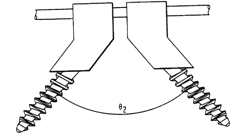
There are many disadvantages associated with current
spinal fixation devices. FIG. 1 show a prior art bone
fixation device that is incapable of capturing spine rods when
the rod capturing assemblies must be rotated to extreme
l0 angles. The design limits pivotal movement to an angle 9i.
One spinal fixation technique involves immobilizing the
spine using orthopedic stabilizing rods, commonly referred to
as spine rods, which run generally parallel to the spine.
This may be accomplished 'by exposing the spine posteriorly and
fastening bone screws to the pedicles of vertebral bodies.
The pedicle screws are generally placed two per vertebra and
serve as anchor points for the spine rods. Clamping elements
adapted for receiving a spine rod therethrough are then used
to join the spine rods to'the pedicle screws. The aligning
influence of the spine rods forces the spinal column to
conform to a more desirable shape. In certain instances, the
spine rods may be bent to achieve the desired curvature of the
spinal column.
U.S. Patent 5,129,388 to Vignaud et al. discloses a
2~ spinal fixation device including a pedicle screw having a U
shaped head rigidly connected to an upper end of the screw.
The U-shaped head includes two arms forming a U-shaped channel
for receiving a spine rod therein. The U-shaped head is
internally threaded so that a setscrew having external threads
may be screwed therein. After the pedicle screw has been
inserted into bone and a spine rod positioned in the U-shaped
channel, the set screw is threaded into the internal threads
of the U-shaped channel for securing the spine rod in the
channel and blocking relative movement between the spine rod
CA 02402917 2002-09-11
. 3
and the pedicle screw. The fixation device also includes a
cap covering an upper portion of the U-shaped head to prevent
the arms from spreading apart as the set screw is threaded
into the internal threads of the U-shaped head.
Surgeons have encountered considerable difficulty when
attempting to insert spinal fixation devices such as those
disclosed in the above-mentioned '388 patent. This is because-
the U-shaped heads atop adjacent screws are often out of
alignment with one another due to curvature of the spinal
column and the different orientation of adjacent pedicles
receiving the screws. As a result, spine rods must often be
bent in multiple planes in order to pass the rods through
adjacent U-shaped channels. This "bending the spine rod"
solution serves to weaken the strength of the assembly and
results in significantly longer operations, which increases
the likelihood of surgical complications.
In response to the above-noted problems, U.S.
Patent 5,733,286 to Errico et al., U.S. Patent 5,672,176 to
Biedermann et al., and U.S. Patent 5,476,464 to Metz-
2o Stavenhagen disclose polyaxial spinal fixation devices wherein
the anchoring element fixed to the bone has a spherically-
shaped head. The fixation devices in the above-identified
patents also have orthopedic rod capturing assemblies for
securing orthopedic rods in the capturing assemblies and
z~ connecting the rods with the anchoring elements. The
spherically shaped heads of the anchoring elements permit
movement of the rod capturing assemblies relative to the
anchoring elements.
In spite of the above-mentioned devices, there remains a
3o need for improved spinal fixation devices. In particular,
there remains a need for spinal fixation devices that provide
an increased degree of angulation between the rod capturing
assemblies and the anchoring elements so as to facilitate
CA 02402917 2002-09-11
4
capturing orthopedic stabilizing rods within the rod capturing
assemblies.
Summary Of The Invention
In one preferred embodiment of the present invention, a
fixation assembly includes a coupling element having a first
section with a first bore coaxial with a first longitudinal
axis and a second section with a second bore coaxial with a
second longitudinal axis transverse to the first longitudinal
axis. The first bore extends from an upper end of the
i0 coupling element and the second bore extends from the lower
end of the coupling element. The coupling element also
includes rod-receiving openings extending from the upper end
thereof. The fixation assembly anchoring element having a
first end for insertion into bone and a longitudinal axis.
The first and second bores of the coupling element extend in
directions that are tilted with respect to one another, as
their associated first and second longitudinal axes are
disposed transversely to one another. Due to the biased
angulation of the coupling element, the coupling element can
2o be manipulated to cover a broader range of , angles for
capturing an orthopedic stabilizing rod.
In certain preferred embodiments, the anchoring element
is integrally connected to a lower end of the coupling
element. In other preferred embodiments, the anchoring
element comprises a separate member assembled with the
coupling element, whereby the coupling element and anchoring
element are pivotable and rotatable relative to one another
for capturing a spine rod in the rod receiving openings of the
coupling element.
3o Achieving sufficient angulation between anchoring
elements while engaging the orthopedic rod is essential for
assemblies mounted in spines having abnormal curvatures.
Sufficient angulation is also important in the cervicothoracic
junction of the spine.
CA 02402917 2002-09-11
After being assembled together, the coupling element and
the anchoring element are preferably pivotable and rotatable
relative to one another. The coupling element preferably
includes a seat adjacent the lower end thereof that is shaped
5 to facilitate pivotal movement of the coupling element and
anchoring element relative to one another.
In certain preferred embodiments, the seat is shaped to
allow the coupling element to pivot with respect to the
anchoring element. Before the coupling element is locked into
l0 place with respect to the anchoring element, the coupling
element is pivotable and rotatable for capturing a spine rod
in the rod receiving openings thereof. The combination of the
pivotable coupling element and the tilted arrangement of the
first and second portions of the coupling element enable the
coupling element to move over a broader range of angles for
capturing a spine rod.
The anchoring element preferably has a second end remote
from the first end, and a head at the second end having an
underside for engaging the seat. The assembly preferably
2o includes a locking element engageable with the coupling
element for locking the rod in the coupling element, after the
rod has been received in the rod-receiving openings. The
locking element forces the head against the seat of the
coupling element to lock the position of the coupling element
35 with respect to the anchoring element.
The head may have a depression adapted to receive a
driver for driving the anchoring element into bone. The
depression in the head may be one or more slots or a hexagonal
opening. The anchoring element may include a neck between the
30 head and the first end thereof. The neck preferably has a
reduced diameter portion for facilitating pivotal movement of
the coupling element and the anchoring element relative to one
another. The reduced diameter neck may have a concave surface
located adjacent an underside of the head.
CA 02402917 2002-09-11
6
The head and seat may have many shapes. In certain
preferred embodiments, the head has an underside with a convex
shape for engaging the seat. The seat may be defined by an
interior wall of the coupling element having an inwardly
tapering conical shape. In other preferred embodiments, the
seat may be defined by an interior wall of the coupling
element having a convex or spherical shape.
The coupling element preferably has an exterior surface,
an upper end and a lower end, and rod-receiving openings that
are open on the upper end and extend toward the lower end.
The coupling element preferably has cuts formed between the
exterior surface and the rod-receiving openings for minimizing
the width of the coupling element. As a result, adjacent
coupling elements may be more closely packed adjacent one
IS another, because the cuts result in the coupling elements
having less width.
In certain preferred embodiments, the anchoring element
is a screw fastener having screw threads extending between the
first and second ends thereof. The anchoring element may
2o include barbs on an outer surface thereof so that withdrawal
of the anchoring element from bone is hindered by the barbs.
The anchoring element may also include an elongated shaft
having holes defined therein for receiving bone graft material
or allowing ingrowth of bone. The anchoring element may also
25 include a hook for anchoring into bone.
The coupling element may include a chamfer adjacent the
first bore for facilitating assemblies of the anchoring
element with the coupling element. The coupling element may
have opening surfaces defining the rod receiving openings and
30 the chamfer may extend from one of the opening surfaces to an
inner surface defining the first bore.
In another preferred embodiment of the present invention,
a bone fixation assembly includes a coupling element having an
upper end defining a first plane and having rod receiving
CA 02402917 2002-09-11
7
openings, a lower end defining a second plane that intersects
the first plane, and at least one bore extending between the
upper and lower ends. The at least one bore is adapted to
receive an anchoring element. The assembly includes an
anchoring element having a first end insertable into bone that
is assembled with the coupling element.
The head of the anchoring element preferably has one or
more depressions formed therein adapted for receiving a driver
for driving the anchoring element into bone. The anchoring
i0 element preferably includes a reduced diameter neck for
facilitating pivotal movement of the coupling element with
respect to the anchoring element.
In further preferred embodiments of the invention, a
coupling element has an upper end and a lower end and
comprises a first section extending from the upper end toward
the lower end of the coupling element. The first section has
a first bore coaxial with a first longitudinal axis. The
coupling element has a second section extending from the lower
end toward the upper end of the coupling element. The second
section has a second bore coaxial with a second longitudinal
axis transverse to the first longitudinal axis. As a result,
the first and second bores extend in directions that are
angled relative to one another. The coupling element includes
rod-receiving openings extending from the upper end toward the
lower end that are adapted to receive an orthopedic rod.
The inner surface of the coupling element adjacent upper
end preferably includes threads for engaging external threads
on a locking element for locking an orthopedic rod with the
coupling element. The locking element is threaded into the
internal threads of the coupling element after spine rod has
been captured in rod receiving openings.
In certain preferred embodiments, the coupling element
has an outer surface with gripping notches for engagement by
an instrument so that the coupling element may be positioned
CA 02402917 2002-09-11
8
with respect to an orthopedic rod. The notches may include
indentations or protrusions provided therein for centering the
instrument on the coupling element.
In still another preferred embodiment of the present
invention, a coupling element for a pedicle screw assembly
comprises an upper end defining a first plane, a lower end
defining a second plane, and at least one bore extending
between the upper and lower ends adapted to receive an
anchoring element. The first and second planes intersect one
l0 another. The first plane and the second plane preferably have
an intersection defining an angle of about 20-30°. In more
preferred embodiments, the angle between the first and second
intersecting planes is about 25° ~ 2°. In highly preferred
embodiments, the angle between the intersecting planes is
approximately 24°.
In yet another preferred embodiment of the present
invention, a coupling element for a pedicle screw assembly
includes a first section at an upper end of the coupling
element, the first section having a first bore coaxial with
2o first longitudinal axis, and a second section at a lower end
of the coupling element, the second section having a second
bore coaxial with a second longitudinal axis. The first and
second longitudinal axes preferably intersect one another.
The assembly includes an anchoring element, such as a screw
thread. The bone anchoring portion of the anchoring element
is adapted to proj ect through the second bore opening at the
lower end of the coupling element when the coupling element
and anchoring element are assembled together.
In still another preferred embodiment of the present
3o invention, a method of stabilizing an area of the spine
includes anchoring an anchoring element into bone. The
anchoring element is assembled with a coupling element having
a first bore and a second bore that are tilted with respect to
CA 02402917 2002-09-11
9
one another. The anchoring element projects through the
second bore opening at a lower end of the coupling element so
that the coupling element and anchoring element axe movable
relative to one another. The position of the coupling element
is adjustable with respect to the anchoring element so that
rod receiving openings extending from an upper end of the
coupling element may receive an orthopedic rod. After the rod
is captured in the rod-receiving openings, the position of the
coupling element is locked with respect to the anchoring
element using a locking element that exerts a downward locking
force on the spine rod, which in turn forces the head of the
anchoring element into the seat of the coupling element.
The coupling element desirably has the first bore
extending through the first section and the second bore
extending through the second section. The anchoring element
and coupling element are preferably assembled by inserting the
anchoring element into the first bore.
Before the coupling element and anchoring element are
locked, the position of the coupling element may be adjusted
2o by pivoting the coupling element with respect to the anchoring
element so that the rod receiving openings engage an
orthopedic rod disposed at a position displaced from the
longitudinal axis of the anchoring element.
Brief Description Of The Drawings
35 These and other objects, features and advantages of the
present invention will be more readily apparent from the
detailed description of preferred embodimEnts set forth below,
taken in conjunction with the accompanying drawings, in which:
FIG. 1 shows a side elevation view of a prior art bone
30 fixation assembly.
FIG. 2 shows a simplified view of a pair of bone fixation
assemblies coupled with an orthopedic stabilizing rod, in
accordance with certain preferred embodiments of the present
invention.
CA 02402917 2002-09-11
.fIG. 3 is a top plan view of a coupling element of a bone
fixation assembly, in accordance with a preferred embodiment
of the present invention.
FIG. 4 is a left side elevation view of the coupling
5 element of FIG. 3.
FIG. 5 is a front elevation view of the coupling element
of FIGS. 3-4.
FIG. 6 is a perspective view of the coupling element of
FIGS. 3-5 .
l0 FIG. 7 is a cross-sectional view of the coupling element
of FIG. taken long line 7-7 thereof.
5 a
FIG. 8 is a front elevation view of an anchoring element,
in accordance ith certain preferred embodiments of the
w
present nvention .
i
FIG. 9 is a top plan view of the anchoring element of
FIG. 8.
FIG. 10 is a right side elevation view, partially in
section, of the anchoring element of FIGS. 8-9 partia lly
assembled with the
coupling
element
of FIGS.
3-7.
FIG. 11 is a right side elevation view, partially in
section, of the coupling element and anchoring element of
FLG. 10 uring
d a further
assembly
step.
FIG. 12 is a right side elevation view, partially in
section, of the coupling element and anchoring element of
2~ FIG. 11, whereby the anchoring element is fully seated in the
coupling element.
FIG. 13 is a right side elevation view, partially in
section, of the coupling element and anchoring element of
FIGS. 10- 12, with the anchoring element secured in bone.
FIG. 14 is a right side elevation view, partially in
section, of the coupling element and anchoring element of
FIG. 13, coupling element pivoted about a head of the
with the
anchoring element.
CA 02402917 2002-09-11
11
FIG. 15 is a right side elevation view, partially in
section, of the bone fixation assembly of FIG. 14 with a spine
rod captured in the coupling element and held in place by a
locking element.
S FIG. 16 is a front elevation view, partially in section,
of the coupling element, anchoring element, of locking element
and spinal rod shown in~ FIG. 16.
FIG. 17 is a cross-sectional view of an anchoring element
of a bone fixation assembly, in accordance with another
preferred embodiment of the invention.
FIG. 18 is a perspective view of a coupling element of a
bone fixation assembly, in accordance with another preferred
embodiment of the present invention.
FIG. 19 is a right side elevation view of the coupling
element of FIG. 18.
FIG. 20 is a top plan view of the coupling element of
FIGS. 18-19.
FIG. 21 is the cross-sectional view of the coupling
element of FIG. 20 taken along line 21-21 in FIG. 20.
FIG. 22 is the cross-sectional view of the coupling
element of FIG. 21 taken along line 22-22 in FIG. 21.
FIG. 23 is an elevation view of two bone fixation
assemblies secured to a stabilizing rod, in accordance with
preferred embodiments of the present invention.
FIG. 24 is a perspective view of the two bone fixation
assemblies of FIG. 23.
FIG. 25 is a perspective view of a coupling element of a
bone fixation assembly, in accordance with further preferred
embodiments of the present invention.
FIG. 26 is a cross sectional view of the coupling element
of FIG. 25.
FIG. 27 is a top view of the coupling element of FIG. 26
taken along axis B-B thereof.
CA 02402917 2002-09-11
12
FIGS. 28A and 28B show respective top plan and side
elevation views of a blank used to make a coupling element of
a bone fixation assembly, in accordance with certain preferred
embodiments of the present invention.
FIG. 29 shows a front elevation view of a coupling
element, in accordance with certain preferred embodiments of
the present invention.-
FIG. 30 shows a top plan view of the coupling element of
FIG. 29 along axis A-A thereof.
l0 FIG. 31 shows a side elevational view of the- coupling
element of FIG. 29.
FIG. 32A shows a top plan view of the coupling element of
FIG. 31 along axis B-B thereof.
FIG. 32B shows a cross-sectional view of the coupling
element of FIG. 32A taken along line 32B-328 thereof.
FIG. 32B-1 shows an expanded view of a section of the
coupling element shown in FIG. 32B.
FIG. 33 shows a perspective view of an anchoring element
of a bone fixation assembly, in accordance with certain
2o preferred embodiments of the present invention.
FIG. 34 shows a top plan view of the anchoring element
shown in FIG. 33.
FIGS. 35A and 35B show respective side elevation and
cross-sectional views of the anchoring element shown in
FIG. 33.
FIGS. 36A-36C show respective perspective, top plan and
cross-sectional views of a locking element threadable into the
coupling element of FIGS. 29-32B-1, in accordance with certain
preferred embodiments of the present invention.
FIG. 37A shows an exploded view of a bone fixation
assembly including a coupling element, a fastening element and
a locking element, in accordance with certain preferred
embodiments of the present invention.
CA 02402917 2002-09-11
13
FIGS. 37B and 38 show respective side elevation and front
elevation views of the bone fixation assembly of FIG. 37A
after the coupling element, anchoring element and locking
element have been assembled together.
FIG. 39 shows a cross-sectional view of the bone fixation
assembly shown in FIG. 37B.
FIG. 40 shows a fragmentary view of a driver including a
lower end having spaced fingers for engaging a head of an
anchoring element, in accordance with certain preferred
embodiments of the present invention.
FIG. 41 shows a cross-sectional view of the driver of
FIG. 41 engaging the head of the anchoring element.
FIG. 42 shows a perspective view of the driver of FIG. 42
engaging the head of the anchoring element.
Best Mode of Carrying Out Invention
Referring to FIG. 2, the present invention is generally
related to providing bi-axial coupling elements that are
capable of pivoting over a broader range of angles (e.g. to an
angle AZ of up to about 110°), thereby providing for greater
angulation than is possible with the prior art devices shown
in FIG. 1.
FIGS. 3-16 show a bone fixation assembly, in accordance
with certain preferred embodiments of the present invention.
The bone fixation assembly may be secured to the pedicles of
vertebral bodies of a spinal column. Referring to FIGS. 3-7,
the fixation assembly includes a coupling element 12
preferably made of a biologically inert material, preferably
any metal customarily used for surgical devices and
particularly those used for bone screws and pins, such as
titanium or stainless steel. Other suitable materials for the
coupling element include alloys, composite materials, ceramics
or carbon fiber materials. Coupling element 12 has an upper.
end 14 and a lower end 16. The upper end 14 defines a first
plane 23 and the lower end 16 defines a second plane 25, the
CA 02402917 2002-09-11
14
first and second planes 23, 25 preferably intersecting one
another.
The coupling element 12 includes a first section 18 that
extends from upper end 14 to an intermediate region 20, and a
second section 21 that extends from intermediate region 20 to
lower end 16. The first section 18 has a first bore extending
therethrough, which is coaxial with a first longitudinal axis
22. The second section 21 has a second bore extending
therethrough, which is coaxial with a second longitudinal axis
l0 24. The first and second longitudinal axes 22, 24 are
preferably angled relative to one another. As a result, the
first bore extending through the first section 18 has an
orientation that is non-parallel or tilted in relation to the
second bore extending through the second section 22 (see FIG.
t5 4 ) .
Referring to FIG. 4, the angle oc formed between the first
and second longitudinal axes 22, 24 may comprise any angle
greater than 0° up to but not including 90°. The specific
angle a may depend upon the particular application for the
2o fixation assembly 10. Preferably, the angle a is
approximately between 20-30°. In more preferred embodiments,
the angle a is approximately 25° ~ 2°. In highly preferred
embodiments, the angle a is approximately 24°. The coupling
elements 12 may be provided in a set, with each coupling
25 element 12 having a slightly different shape and unique angle.
During surgery, a surgeon may select a coupling element from
the set having an appropriate angle for the particular patient
and/or the particular location along a patient's spine.
The coupling element 12 may have other shapes, such as a
30 Polyaxial structure having more than two cylinders (e. g.,
three), with each cylinder transverse to the other cylinders.
In other preferred embodiments, the cylinders may have non
CA 02402917 2002-09-11
circular cross-sectional shapes, such as square, pentagonal,
elliptical, etc.
Referring to FIGS. 5-7, coupling element 12 also
desirably has a substantially cylindrical outer surface 26
5 that extends from upper end 14 to a convex surface 28 adjacent
lower end 16. Coupling element 12 also preferably includes
one or more notches 30 formed in outer surface 26- so that-
coupling element 12 may be secured by a tool, such as a
persuader instrument. The notches 30 preferably extend in
10 directions transverse to the first longitudinal axis 22.
Referring to FIG. 7, coupling element 12 has an inner
surface 38 surrounding the first bore 40, which extends from
upper end 14 toward lower end 16 and is preferably coaxial
with first longitudinal axis 22. The inner surface 38
15 preferably includes internal threads 44 extending from upper
end 14 toward lower end 16. The coupling element 12 has
second bore 41 that extends from lower end 16 toward upper end
14. The second bore 41 is coaxial with second longitudinal
axis 24.
Referring to FIGS. 5-6, coupling element 12 has a pair of
rod receiving openings 42 that extend from outer surface 26 to
inner surface 38, each rod receiving opening 42 communicating
with first bore 40. The rod receiving openings 42 are adapted
to capture and seat an orthopedic stabilizing rod therein.
The rod receiving openings 42 preferably comprise U-shaped
openings having the respective open ends adjacent upper end 14
of coupling element 12 and the respective closed ends remote
from the open ends.
The rod-receiving openings divide coupling element 12
3o into a first arm 31A on one side of the openings 42 and a
second arm 31B on an opposite side of the rod-receiving
openings 42. The rod-receiving openings 42 preferably include
cuts 32 formed adjacent outer surface 26 of coupling element
12. Although the present invention is not limited by any
CA 02402917 2005-11-07
16
particular theory of operation, it is believed that the cuts
32 enable two or more coupling elements 12 to be packed closer
together than would be possible for coupling elements having
the cuts omitted.
Referring to FIGS. .6 and 7, the coupling element 12
preferably has a chamfer 45 that extends from upper end 14
toward an internal cavity 46. The chamfer 45 preferably
extends between the opening surface 43 of one of the rod
receiving openings 42 to the inner surface 38 on the first
section 18. The chamfer 45 facilitates the insertion of an
anchoring element into the coupling element 12;
notwithstanding the angle of first bore 40 with respect to
second bore 41. In certain preferred embodiments, the chamfer
45 is bored out of the material of coupling element 12 to
essentially form a third axis that is coaxial with second bore
41 and second axis 24. The chamfer 45 preferably provides
room for an anchoring element and driver to pass therethrough
when securing the anchoring element in bone. In other
preferred embodiments, the dimensions of the coupling element
and anchoring element may be selected to allow the anchoring
element to be inserted into the coupling element, without
requiring a chamfer.
Referring to FIG. 7, coupling element 12 includes a seat
50 adjacent lower end 16 for engaging an anchoring element.
The seat 50 preferably has a conical shape with sidewalls 52
tapering inwardly toward lower end 16. In other preferred
embodiments, the seat 50 is substantially spherical or concave
in shape.
Referring to FIGS. 8-9, the fixation assembly preferably
includes an anchoring element 52, such as a screw fastener,
having a tip end 54 for insertion into bone, a head 56 at an
upper end thereof, and external screw threads 58 that extend
between tip end 54 and head 56. The screw threads 58 have an
inner diameter 64 and an outer diameter 66. The screw threads
CA 02402917 2002-09-11
17
58 desirably terminate at a neck 60 preferably located between
head 56 and screw threads 58. The neck has a neck diameter 68
that is less .than the outer diameter 66 of the screw threads.
The reduced diameter neck 60 allows the coupling element 12 to
pivot and rotate through a broader range of motion relative to
anchoring element 52. The anchoring element 52, including the
screw threads 58, neck 60 and head 56, are preferably made bf
a biologically inert material, such as titanium or stainless
steel.
Head 56 desirably includes one or more depressions or
grooves 70 adapted to cooperate with a driver used to screw
the anchoring element 52 into bone. Head 56 is preferably
sized and shaped to pass through the first and second bores
formed in coupling element 12 until an underside of head
engages the seat 50 (FIG. 7) of the coupling element. The
head 56 has an underside 57 that is preferably convex or
spherical in shape for engaging the seat 50. When the
underside 57 of head 56 engages the seat, the tip end 54 and
threaded portion 58 of the anchoring element 52 extend through
the second bore 41 (FIG. 7) at the lower ,end 16 of coupling
element 12.
Referring to FIGS. 10-12, in one preferred method for
assembling anchoring element 52 with coupling element 12, the
tip end 54 of anchoring element 52 is passed through first
bore 40 toward lower end 16 so that screw threads 58 project
from the lower end 16 of coupling element. In certain
preferred embodiments,, the anchoring element 52 may pass
freely through first bore 40 because the outer diameter of the
screw threads 58 may be less than the diameter of first bore
40. In other preferred embodiments, the diameter of the
threads 58 is substantially similar to the diameter of first
bore 40, requiring the anchoring element to be threaded into
the coupling element until the underside 57 of head 56 engages
seat 50. In certain preferred embodiments, the underside 57
CA 02402917 2002-09-11
18
of head 56 is spherical and the seat is conical-shaped. In
other embodiments, the underside 57 of head 56 and seat 50
comprise other shapes, such as a convex underside and a
concave seat.
Referring to FIGS. 13 and 14, after anchoring element 52
has been assembled with coupling element 12, anchoring element
52 and coupling element 12 are free to pivot and rotate
relative to one another. The neck 60 of anchoring element 52
preferably has a reduced-diameter with a concave outer surface
62 so that anchoring element 52 and coupling element 12 may
pivot over a broader range of angles relative to one another,
as compared to an anchoring element on which a reduced
diameter neck is omitted. FIG. 13 shows coupling element 12
in a first position with respect to anchoring element 52.
FIG. 14 shows coupling element 12 in ~a second position with
respect to anchoring element 52 after coupling element has
been rotated counterclockwise relative to the position shown
in FIG. 13.
After anchoring element 52 and coupling element 12 have
2o been assembled together, the subassembly is ready to be
inserted into bone 80. In one preferred embodiment, a pilot
hole is drilled in bone, and anchoring element 52 is placed in
the pilot hole and screwed into the bone 80 using a driver or
tool. As anchoring element 52 is rotated by driver, the
z5 anchoring element advances longitudinally into the bone 80.
The anchoring element 52 is preferably advanced into the bone
80 until it is firmly secured in place such as when the neck
60 of anchoring element is adjacent the bone 80. In other
preferred embodiments, the tip end includes a cutting edge
3o formed therein such as a cutting flute, so that pre-forming a
pilot hole is not required.
After anchoring element 52 is anchored in bone 80,
coupling element 12 remains free to pivot and rotate relative
to anchoring element 52 so that an orthopedic stabilizing rod
CA 02402917 2002-09-11
19
82 may be captured within the rod receiving openings 42 of
coupling element 12. In certain preferred embodiments, after
the anchoring element has been fully inserted into bone, a gap
may exist between the lower end 16 of coupling element 12 and
bone 80. The gap preferably facilitates pivotal and
rotational movement of coupling element 12 relative to
anchoring element 52. In other preferred embodiments, the
lower end 16 of coupling element 12 may engage bone during a
stabilizing procedure when the rod 82 is captured by coupling
element 12. In these embodiments, however, it is not critical
that the lower end 16 of the coupling element 12 contact bone
in order to form a reliable assembly. In other preferred
embodiments, it may be necessary for the lower end 16 of
coupling element 12 to engage bone to provide a reliable,
stable assembly. The coupling element 12 may be moved (e. g.
pivoted) by grasping the coupling element with a tool.
Referring to FIG. 15, after rod 82 has been positioned
within coupling element 12, a locking element 84 such as a set
screw having external threads, is threaded into internal
threads 44 of coupling element 12 until an underside 85 of
locking element 84 abuts against rod 82. Locking element 84
is then further tightened for forcing rod 82 against the
closed ends of the rod receiving openings 42. The tightened
locking element 84 applies a downward force through rod 82
2~ onto the top side 59 of head 56. In other embodiments, the
coupling element 12 has threads on its outer surface 26 and
the locking element comprises an internally threaded sleeve.
Referring to FIGS. I5-16, the downward force applied by
rod 82 to the top side 59 of head 56 forces the underside 57
of head 56 into the seat 50 of coupling element 12. In
embodiments in which the seat 50 has a conical shape and the
underside 57 has a spherical shape, engagement of the
underside 57 with the seat '50 creates a spherical/conical
surface friction lock that locks the position of the coupling
CA 02402917 2002-09-11
element 12 relative to the head 56, thereby preventing further
pivotal and rotary movement of the coupling element 12 and
anchoring element 52 relative to one another. Although the
present invention is not limited by any particular theory of
5 operation, it is believed that the engagement. of the spherical
underside of the head with the conical seat of the coupling
element is a dramatic improvement o er a convex/concave
interface and dramatically improves the locking force exerted
at the interface of the screwhead and the coupling element.
10 In other embodiments, both seat 50 and underside 57 of head 56
have spherical shapes.
In the prior art, it has been observed that some patients
have relatively small vertebrae, making it difficult t.o secure
two or more bone fixation assemblies next to each other over
IS adjacent vertebrae. As a result, in some patients, one or
more vertebrae may not have a section of a stabilizing
assembly attached thereto. This situation may adversely
affect stabilization and fusion of a spine segment because the
entire portion of the spine segment is not being stabilized.
20 Although the present invention is not limited by any
particular theory of operation, it is believed that providing
cuts 32 adjacent the rod receiving openings 42 reduces the
profile or width of the coupling element 12, thereby
minimizing interference with neighboring coupling elements
when a series of coupling elements are connected with a spine
rod. The cuts 32 allow the coupling elements to be packed
tightly together, thereby improving fusion of a spinal
segment. Providing cuts 32 on coupling element 12 also
minimizes the occurrence of sharp edges that may irritate a
3o patient's tissue or cut through the surgical gloves of medical
personnel.
In certain preferred embodiments, the head of the
anchoring element preferably has an underside defining a first
radial surface and a top side defining a second radial
S
CA 02402917 2005-11-07
21
surface, as disclosed in certain embodiments of U.S. Patent
No. 6, 688, 681.
The second radial
surface has a radius that is smaller than the radius of the
first radial surface, which is believed to provide a lower
overall silhouette for the assembly.
Referring to FIGS. 18-22, in other.preferred embodiments,
coupling element 11:2 includes a first bore 140 extending
through a first section 118 coaxial with a first longitudinal
axis 122 and a second bore 141 extending through a second
section 121 a second longitudinal axis 124, the first and
second axis defining an angle coaxial with (3 that may comprise
any angle greater than 0° up to but not including 90°.
Preferably, an angle of between 20-30° is used. In more
preferred embodiments, the angle ~3 is preferably about 25° ~
2°. In highly preferred embodiments, the angle (3 is preferably
24°.
The present invention also preferably includes a driver,
such as that disclosed in certain embodiments of U.S. Patent
2o No. 6, 688, 681. _ _
The driver preferably has a rotatable shaft and one
or more fingers extending from an end of the shaft for
engaging the grooves in the head of the anchoring element. In
preferred embodiments, the driver has one finger for each
groove in the head of the anchoring element. The driver may
also have external threads on a shaft that are adapted for
engaging the internal threads of the coupling element when the
anchoring element is anchored to bone. The engagement of the
external threads of the driver and the internal threads of the
coupling element generally stabilizes the assembly when the
anchoring element is secured to bone. Specifically, the
engagement of the threads prevents the coupling element from
CA 02402917 2005-11-07
r ' ' -r ..
22
moving relative to the anchoring element when driving the
anchoring element into bone, thereby facilitating bone
anchoring.
The anchoring element may have expandable head, such as
the expandable head disclosed in certain preferred embodiments
of commonly assigned U. S . Patent No. 6, 554, 834.
The expandable head has a
recess and at least one slot extending between inner and outer
surfaces of the head, which facilitates expansion of the head.
The anchoring element of the '272 patent also has an insert
which can be positioned at least partially in the recess, the
insert having an outer surface and defining an outer dimension
that is greater than the inner dimension of the recess. After
a spinal rod has been positioned within a coupling element, a
locking element associated with the coupling element locks the
orthopedic rod in the rod-receiving opening. The locking
element forces the orthopedic rod into the rod receiving
opening, to in turn force the insert into the recess of the
expandable head. As the insert is forced into the recess, the
outer dimension of the insert bears against the inner
dimension of the head, thereby expanding the outer surface of
the head against a seat of the coupling element for locking
the coupling element from further pivotal movement.
As shown in FIG. 23, pedicle fixation assemblies 110A,
110B may be mounted adjacent one another so as to engage a
spinal rod 82. As shown in FIG. 24, the anchoring elements
152A, 152B may be locked in place with respect to the coupling
elements 112A, 112B so as to form angles with respect to the
3o spinal rod 82, in the xy, xz, or yz planes.
FIGS. 25-27 show a coupling element 212 for a pedicle
fixation assembly in accordance with another preferred
embodiment of the present invention. Coupling element 212 has
an upper end 214 and a lower end 216, the upper end 214
CA 02402917 2002-09-11
23
defining a first plane 223 and the lower end 216 defining a
second plane 225, the first and second planes 223, 225
intersecting one another.
Referring to FIGS. 26-27, coupling element 212 has a
first bore 240 that extends along first axis 222 from upper
end 214 to an intermediate region 220, and a second bore 241
that extends along second axis 224 from lower end 216 of
coupling element 212 to intermediate region 220. The first
bore 240 and second bore 241 are generally oriented
non-parallel or transverse to one another.
The angle 8 between first axis 222 coaxial with first
bore 240 and second axis 224 coaxial with second bore 241 may
comprise any angle greater than 0° up to but less than 90°.
The angle 8 may vary depending upon the particular application
for the coupling element 212. Preferably, the angle 8 is
approximately between 20-30°. In more preferred embodiments,
the angle 8 is approximately 25° ~ 2°. In highly preferred
embodiments, the angle B is approximately 24°.
Referring to FIG. 25, coupling element 212 desirably has
an outer surface 226 that is cylindrical in shape, extending
from upper end 214 to lower end 216. Outer surface 226
preferably includes one or more notches 230 formed therein so
that coupling element 212 may be grasped and/or maneuvered
using a securing element or tool. The notches 230 preferably
extend in directions that intersect first longitudinal axis
222.
Referring to FIGS. 25-27, the first section 218 of
coupling element 212 preferably includes internal threads 244
extending from upper end 214 toward lower end 216. Coupling
element 212 has a pair of rod receiving openings 242 in
communication with first bore 240 that extend from outer
surface 226 to inner surface 238 of coupling element 212. The
rod receiving openings 242 are adapted to seat a spinal rod
CA 02402917 2005-11-07
r. :'
24
(not shown) therein, The rod receiving openings 242
preferably comprise U-shaped openings having open ends
adjacent upper end 214 and closed ends opposite the open ends.
The rod-receiving openings 242 divide coupling element 212
into a first arm 231A and a second arm 2318.
The coupling element 212 has a cavity 246 in second
section 221 and a seat~250 for engaging an anchoring element.
In the particular preferred embodiment shown in FIG. 26, seat
250 is a conical-shaped seat including sidewalls 252 tapering
l0 inwardly toward one another adjacent lower end 216. .In other
preferred embodiments, seat 250 may be substantially spherical
or concave.
FIGS . 28A and 288 show a metal blank 310 used to make a
coupling element, in accordance with other preferred
embodiments of the present invention: The metal blank 310
preferably has a cylindrical outer surface 326, a longitudinal
axis designated A-A, and a lower end 316 that is chamfered.
The metal blank 310 is bored from upper end 314 toward lower
end 316 to form first bore 340 coaxial with longitudinal axis
A-A .
Referring to FIGS. 29-31, coupling element 312 has a rod-
receiving opening 342 that divides opposing arms 331A, 3318
from one another. The coupling element 312 has an outer
surface 326 including a pair of gripping notches 330A,3308 on
each opposing arm 331A, 3318. The opposing gripping notches
330A, 330B may be secured with a tool, such as forceps (not
shown).
Referring to FIGS. 30-31, the opposing pairs of gripping
notches 330A, 3308 are cut into the respective arms 331A, 3318
of coupling element 312. In certain preferred embodiments,
the gripping notches 330A, 3308 are formed using a rotary
cutter, such as a woodruff cutter, that is abutted laterally
against exterior surface 326 of coupling element 312. A first
pair of gripping notches 330A on first arm 331A are separated
CA 02402917 2005-11-07
from one another by a first rib 333A extending therebetween.
Similarly, a second pair of gripping notches 3308 on second
arm 3318 are separated from one another by second rib 3338.
Coupling element 312 has two bores extending therethrough. A
5 first bore 340 extends in a direction substantially parallel
to the axis designated A-A. The first bore 340 is preferably
formed by drilling from the upper end 314 toward the lower end
316 of the coupling element 312. Coupling element 312 also
includes .a second bore.341 extending from the lower end 316
10 toward upper end 314 along axis B-B. In certain preferred
embodiments, the first and second bores 340, 341 may not
extend completely through the length of coupling element 312,
but may meet at an intermediate region between upper end 314
and lower end 316.
15 Referring to FIG. 3l, first bore 340 is coaxial with axis
A-A and second bore 341 is coaxial with axis B-B: The first
bore 340 extends from upper end 314 toward lower end 316 of
coupling element 312, and second bore 341 extends from lower
end 316 toward upper end 314. Upper end 314 of coupling
20 element 312 defines a first plane 423 and lower end 316
defines a second plane 424. The first and second planes 423,
424 are preferably angled relative to one another and
intersect one another.
FIG. 32A shows coupling element 312 including second~bore
25 341 formed from lower end 316 thereof and extending along axis
B-B. Referring to FIG. 328, first bore 340 is coaxial with
axis A-A and second bore 341 is coaxial with axis B-B.
Coupling element 312 includes internal threads 344 extending
from upper end 314 toward lower end 316. The exterior surface
of coupling element 312 adjacent lower end 316 is preferably
chamfered. In certain preferred embodiments, the chamfered
surface is formed by rotating coupling element 312 about axis
B-B and engaging lower end 316 with a grinding tool. An
intermediate region 321 of coupling element 312 includes a
CA 02402917 2005-11-07
retaining lip 343. As will be described in more detail below,
retaining lip 343 prevents an anchoring element such as a
screw fastener from disassembling with coupling element 312
after the coupling element and the anchoring element have been
assembled together. Second bore 341 formed in lower end 316
of coupling element 312 preferably includes a seat 350 having
side walls 351 that taper inwardly toward one another. As
shown in FIG. 32B-1, the side walls 351 and axis B-B
preferably define an angle of approximately 8-12° and more
preferably about 10°
Referring to FIGS. 33-358, the pedicle screw assembly of
the present invention also includes anchoring element 352
(hereinafter referred to as fastening element 352 or screw fastener 352)
having tip end 354 and head 356 remote therefrom. In certain
Preferred embodiments, head 356 has a spherical radius. Head
356 includes evenly spaced cuts 370~formed in the exterior
surface of head 356. In certain preferred embodiments, the
spaced cuts 370 are made using a grinding or milling tool that
.engages the head from lateral sides. Fastening element 352
includes external screw threads 358 having an outer diameter
366 and an inner diameter 364. Fastening element 352 also
includes neck 360 provided between an upper end of screw
threads 358 and head 356. The neck 360 has a concave surface
362: Fastening element 352 also includes a cutting surface
371, such as a cutting flute, formed adjacent tip end 354: As
is known to those skilled in the art, providing a cutting
flute 371 at a tip end 354 of fastening element 352 avoids the
need to pre-tap into bone, which in turn provides for a
tighter, snugger fit between the fastening element 352 and
bone. As the fastening element 352 is screwed into~bone, the
cutting flute 371 cuts into the bone, thereby avoiding the
need to pre-tap the bone. When screwing fastening element 352
in bone, the evenly spaced cuts 370 on head 356 are engaged by
the fingers of a driver, as will be described in more detail
below.
CA 02402917 2005-11-07
,.
27
Referring to FIGS. 36A-36C, fixation assembly also
preferably includes a locking element such as a set screw 390
having an upper end 392, a lower end 394 and external threads
396 extending between the upper and lower ends. Set screw 390
includes a hexagonal shaped opening 398 extending from upper
end 392 toward lower end 394, which is adapted to receive an
end of a hexagonal driver for turning set screw 390.- As will
be described in more detail below, an underside 394 of set
screw 390 is adapted to abut against an orthopedic stabilizing
l0 rod for exerting a downward force on a head of an anchoring
element for locking fixation assembly from further movement.
FIG. 37A-39 show a fixation assembly including coupling
element 312, screw fastener 352 and set screw 390 prior to the
components being assembled together. In one preferred
embodiment, the tip end 354 of screw fastener 352 is passed
through the first bore 340 extending from upper end 314 of
coupling element 312. In certain embodiments, the external
threads 358 of screw fastener 352 must be threaded past
internal threads (not shown) of coupling element 312, however,
2o in other preferred embodiments, the threaded portion may pass
the internal threads by rocking the threaded portion 358 bac k
and forth until the threaded portion 358 of screw fastener 352
clears a lower end of the internal threads. After the threads
358 of screw fastener 352 have cleared the interval threads of
coupling element 312, the head 356 of,screw fastener 352 is
press fit into seat 350 adjacent lower end 316 of coupling
element 312. The head 356 of screw fastener 352 preferably
has a diameter that is slightly greater than the diameter of
the bore at retaining lip 343. As head 356 is pushed through
retaining lip 343, the retaining lip 343 is slightly deformed
to allow the head to pass into seat 350. Once head 356 passes
retaining lip 343, the retaining lip 343 springs back to a
diameter that is smaller than the outer diameter of head 356.
As a result, head 356 is captured in seat 350 of coupling
CA 02402917 2005-11-07
28
element 312 between retaining lip 343 and the opening at the
lower end 316 of coupling element 312. Once the head 356 is
captured within seat 350, the screw fastener 352 and coupling
element-312 are able to pivot and rotate relative to one
another. .
Referring to FIGS. 40-42, after the head 356 of anchoring
element 352 has been captured within the seat 350 'of coupling
element 312, the bone fixation assembly is ready to be
anchored into bone and coupled with an orthopedic stabilizing
rod. In one preferred embodiment, a driver 421 including
shaft 423 having lower end 426 with spaced fingers 427
projecting therefrom is placed in substantial alignment over
head 356 of screw fastener 352. The fingers 427 are
preferably substantially rigid so as to limit flexing or
bending of the fingers 427 as forces are exerted upon the
fingers. The fingers 427 are then seated in spaced cuts 330
of head 356. Driver 421 also includes a shaft 423 having
external threads 429 adapted to mesh with the internal threads
344 of coupling element 312 for stabilizing coupling element
312 and screw fastener 352 as screw fastener 352 is threaded
into bone. Driver 421 also preferably includes a sleeve 425
slidable along shaft 423 for sliding over exterior surface 326
of coupling element 312 to further stabilize the fixation
assembly when threading fastening element 352 into bone.
Although the invention herein has been described with
reference to particular embodiments, it is to be understood
that these embodiments are merely illustrative of the
principles and applications of the present invention. It is
therefore to be understood that numerous modifications may be
made to the embodiments disclosed herein and that other
arrangements may be devised without departing from the spirit
and scope of the present invention as defined by the appended
claims.
CA 02402917 2002-09-11
Industrial Applicability
29
The present invention has applicability in the orthopedic
industry.