Note: Descriptions are shown in the official language in which they were submitted.
CA 02430004 2003-05-28
1
Rotary positive-displacement pump with meshing gear wheels
without encapsulation, and gear wheel for such a
positive-displacement pump
This invention relates to the sector of rotary positive-
displacement pumps. Various types of rotary pumps are known,
amongst which are gear pumps, lobe pumps and screw pumps.
Gear pumps generally consist of two gear wheels, one of
which, termed the driving gear, is connected to a drive shaft
and drives the other gear, termed the driven gear, in
rotation.
Document EP-1 132 618 by the same applicant, the content of
which is intended to be incorporated herein by reference,
relates to a rotary positive-displacement gear pump in which
the gear wheels comprise a plurality of meshing teeth without
encapsulation and at the same time incorporating helical
teeth with face contact substantially equal or close to
unity. The combination of a tooth profile which avoids
encapsulation and the helical development of the teeth
reduces the ripple and noise resulting from it while the pump
is operating.
Experiments carried out by the applicant on various gears to
be used in pumps of known type of the type indicated above
revealed that there is a defined range of tooth profiles
which can be effective both in reducing the noise of the pump
and at the same time in making manufacture relatively simple,
which may assist in containing the production costs of
CA 02430004 2003-05-28
2
positive-displacement pumps. Moreover, this series of
specifically identified profiles has the advantage of a high
level of reliability in use, which makes its use in positive-
displacement pumps for high pressures particularly
advantageous.
In order to achieve the aims indicated above, the subject of
the invention is a gear wheel with a plurality of teeth
capable of meshing with the teeth of another corresponding
gear wheel, the profile of each tooth of the gear wheel, in
cross-section, being defined in the claims below.
In particular, the profile of at least one tooth of one of
the two rotors is defined by a natural spline function
passing through a plurality of nodal points having pre-
established coordinates, with a tolerance of ~ 1/20th of the
depth of the tooth on the theoretical profile defined by the
plurality of preferred nodal points. The nodal points are
defined by a pair of values {X', Y'} expressed in a system of
Cartesian coordinates having their origin at the centre of
the pitch circle of the gear wheel.
A further subject of this invention is a rotary positive-
displacement pump comprising a pair of meshing gear wheels
having a tooth profile of the type indicated above.
Further characteristics and advantages will emerge from the
description below of a preferred form of embodiment, with
reference to the attached drawings, given purely as a non-
limiting example, in which:
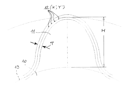
- figure 1 shows the profile of a gear wheel tooth according
to the invention, indicating the band of tolerance of the
profile relative to the depth of the tooth, and
CA 02430004 2003-05-28
3
- figures 2 to 7 illustrate theoretical profiles of teeth of
gear wheels having numbers of teeth respectively equal to
five, six, seven, eight, nine and ten.
With reference to figure 1, a gear wheel 10 according to the
invention, designed to mesh with another corresponding gear
wheel (not shown) for use in a rotary positive-displacement
pump, preferably of the type for high operating pressures,
comprises a plurality of teeth 11 with a depth H and a
profile capable of meshing without encapsulation with the
teeth of the other corresponding gear wheel . The prof ile of
the teeth 11 is not describable as a succession of simple
geometric curves, but can be defined by a natural spline
function passing through a plurality of nodal points 12
defined by pairs of values expressed in a system of Cartesian
coordinates having their origin at the centre O of the pitch
circle 13 of the gear wheel 10.
Experiments carried out by the applicant led to the
identification of a series of tooth profiles especially
suitable for producing gear wheels with five, six, seven,
eight, nine or ten teeth each. The actual profile of the
teeth 11 may fall within a band of tolerance T the width of
which is ~ 1/20th of the depth H of the tooth of the gear
wheel.
CA 02430004 2003-05-28
4
Example 1
A gear wheel having a number of teeth equal to five has a
theoretical tooth profile illustrated in figure 2, defined by
a natural spline function passing through a plurality of
nodal points defined by a pair of values {X' , Y' } expressed
in a system of Cartesian coordinates having their origin at
the centre O of the pitch circle P of the gear wheel. The
coordinates of the nodal points vary in a manner similar to
the pairs of values {X, Y} in the List shown in table 1
below.
X Y X Y X Y X Y
0.00 20.00 3.93 17.22 5.15 14.26 5.43 11.85
0.37 19.98 4.02 17.07 5.20 14.09 5.45 11.78
0.73 19.93 4.11 16.91 5.21 13.91 5.47 11.69
1.09 19.85 4.19 16.75 5.26 13.74 5.50 11.62
1.44 19.74 4.27 16.59 5.29 13.56 5.52 11.54
1.78 19.58 4.35 16.43 5.32 13.38 5.55 11.46
2.09 19.40 4.42 16.27 5.34 13.21 5.58 11.37
2.39 19.19 4.49 16.11 5.35 13.03 5.61 11.29
2.66 18.97 4.57 15.95 5.36 12.85 5.64 11.21
2.91 18.71 4.63 15.78 5.36 12.77 5.67 11.13
3.13 18.44 4.69 15.62 5.35 12.68 5.71 11.04
3.24 18.29 4.77 15.45 5.34 12.51 5.75 10.97
3.34 18.14 4.83 15.28 5.35 12.43 5.99 10.54
3.45 17.99 4.89 15.12 5.36 12.26 6.20 10.25
3.55 17.83 4.94 14.95 5.37 12.17 6.43 9.99
3.65 17.68 5.01 14.78 5.38 12.09 6.67 9.75
3.74 17.53 5.05 14.61 5.40 12.02 6.93 9.54
3.84 17.37 5.12 14.43 5.41 11.93
Table 1
Example 2
A gear wheel having a number of teeth equal to six has a
theoretical tooth profile illustrated in figure 3, defined by
a natural spline function passing through a plurality of
nodal points defined by a pair of values {X', Y'} expressed
in a system of Cartesian coordinates having their origin at
the centre O of the pitch circle P of the gear wheel. The
CA 02430004 2003-05-28
coordinates of the nodal points vary in a manner similar to
the pairs of values {X, Y} in the list shown in table 2
below.
X Y X Y X Y X Y
0.00 19.50 3.51 16.75 4.45 13.98 4.59 12.75
0.34 19.48 3.58 16.64 4.48 13.86 4.60 12.71
0.68 19.43 3.65 16.53 4.49 13.72 4.62 12.66
1.01 19.34 3.71 16.40 4.49 13.59 4.62 12.61
1.33 19.24 3.77 16.27 4.48 13.66 4.63 12.56
1.64 19.09 3.83 16.14 4.47 13.61 4.65 12.51
1.92 18.89 3.94 15.88 4.48 13.56 4.67 12.42
2.19 18.69 4.00 15.74 4.48 13.49 4.68 12.36
2.43 18.46 4.05 15.60 4.47 13.44 4.71 12.30
2.65 18.21 4.06 15.46 4.47 13.37 4.85 11.99
2.83 17.94 4.10 15.33 4.47 13.31 4.99 11.74
2.90 17.81 4.15 15.19 4.48 13.25 5.12 11.55
2.98 17.70 4.20 15.05 4.49 13.18 5.28 11.37
3.04 17.57 4.24 14.92 4.50 13.13 5.44 11.20
3.12 17.45 4.28 14.77 4.52 13.06 5.61 11.04
3.18 17.32 4.31 14.64 4.53 13.01 5.78 10.91
3.25 17.25 4.34 14.51 4.55 12.95 5.97 10.78
3.32 17.12 4.38 14.38 4.56 12.91 6.18 10.65
3.37 16.99 4.41 14.25 4.57 12.85
3.44 16.88 4.43 14.11 4.58 12.81
Table 2
Example 3
A gear wheel having a number of teeth equal to seven has a
theoretical tooth profile illustrated in figure 4, defined by
a natural spline function passing through a plurality of
nodal points defined by a pair of values {X', Y'} expressed
in a system of Cartesian coordinates having their origin at
the centre O of the pitch circle P of the gear wheel. The
coordinates of the nodal points vary in a manner similar to
the pairs of values {X, Y} in the list shown in table 3
below.
CA 02430004 2003-05-28
6
X Y X Y X Y X Y
0.00 19.10 3.05 16.72 3.76 14.75 4.03 13.16
0.33 19.09 3.12 26.61 3.73 14.60 4.05 13.10
0.64 19.05 3.18 16.52 3.76 14.50 4.06 13.05
0.95 18.96 3.19 16.41 3.76 14.39 4.07 12.98
1.25 18.83 3.25 16.32 3.82 14.28 4.09 12.95
1.53 18.69 3.25 16.21 3.84 14.19 4.13 12.86
1.79 18.49 3.32 16.09 3.85 14.04 4.18 12.79
2.04 18.28 3.34 15.98 3.86 13.85 4.25 12.62
2.25 18.09 3.43 15.88 3.8$ 13.76 4.33 12.45
2.45 17.83 3.42 15.79 3.86 13.73 4.51 12.27
2.59 17.58 3.46 15.67 3.86 13.67 4.57 12.15
2.65 17.46 3.53 15.57 3.89 13.60 4.77 11.98
2.67 17.37 3.52 15.46 3.90 13.56 4.84 11.88
2.78 17.29 3.59 15.37 3.92 13.48 4.95 11.75
2.83 17.17 3.61 15.28 3.94 13.45 5.11 11.67
2.88 17.12 3.65 15.17 3.94 13.36 5.29 11.55
2.94 17.01 3.68 15.06 3.96 13.31 5.43 11.49
2.95 16.92 3.66 14.96 3.97 13.25 5.51 11.45
3.03 16.81 3.74 14.84 3.99 13.24
Table 3
Example 4
A gear wheel having a number of teeth equal to eight has a
theoretical tooth profile illustrated in figure 5, defined by
a natural spline function passing through a plurality of
nodal points defined by a pair of values {X', Y'~ expressed
in a system of Cartesian coordinates having their origin at
the centre O of the pitch circle P of the gear wheel. The
coordinates of the nodal points vary in a manner similar to
the pairs of values {X, Y} in the list shown in table 4
below.
CA 02430004 2003-05-28
7
X Y X Y X Y X Y
0.00 18.80 2.66 16.68 3.24 14.92 3.50 13.67
0.29 18.78 2.70 16.59 3.26 14.83 3.50 13.61
0.58 18.73 2.74 16.50 3.27 14.73 3.56 13.40
0.88 18.65 2.77 16.41 3.30 14.63 3.63 13.25
1.15 18.53 2.80 16.33 3.31 14.55 3.71 13.12
1.41 18.39 2.83 16.26 3.32 14.45 3.77 13.00
1.64 18.22 2.87 16.17 3.34 14.37 3.85 12.86
1.87 18.03 2.91 16.09 3.35 14.29 3.94 12.74
2.05 17.83 2.94 16.00 3.37 14.15 4.02 12.64
2.21 17.61 2.98 15.93 3.38 14.13 4.12 12.55
2.36 17.36 3.01 15.84 3.39 14.06 4.22 12.47
2.40 17.28 3.04 15.76 3.41 14.02 4.32 12.38
2.45 17.20 3.08 15.67 3.42 13.97 4.42 12.30
2.48 17.12 3.10 15.59 3.44 13.92 4.52 12.24
2.52 17.04 3.12 15.49 3.46 13.83 4.64 12.18
2.56 16.94 3.15 15.42 3.46 13.78 4.74 12.12
2.59 16.85 3.18 15.22 3.47 13.75 4.87 12.08
2.63 16.77 3.20 15.12 3.49 13.72 4.97 12.01
Table 4
Example 5
A gear wheel having a number of teeth equal to nine has a
theoretical tooth profile illustrated in figure 6, defined by
a natural spline function passing through a plurality of
nodal points defined by a pair of values {X', Y'~ expressed
in a system of Cartesian coordinates having their origin at
the centre O of the pitch circle P of the gear wheel. The
coordinates of the nodal points vary in a manner similar to
the pairs of values {X, Y} in the list shown in table 5
below.
CA 02430004 2003-05-28
8
X Y X Y X Y X Y
0.00 18.50 2.48 16.41 2.91 15.00 3.21
13.71
0.27 18.48 2.52 16.33 2.92 14.93 3.24 13.67
0.54 18.43 2.55 16.26 2.95 14.86 3.26 13.63
0.81 18.36 2.57 16.20 2.97 14.78 3.28 13.58
1.06 18.25 2.61 16.12 2.98 14.71 3.37 13.42
1.30 18.12 2.64 16.06 2.99 14.67 3.45 13.30
1.52 17.96 2.67 15.99 2,99 14.57 3.53 13.20
1.71 17.78 2.69 15.92 2,99 14.53 3.62 13.10
1.88 17.59 2.71 15.85 3.02 14.43 3.72 13.00
2.02 17.38 2.73 15.77 3.03 14.38 3.81 12.92
2.15 17.16 2.75 15.71 3.04 14.29 3.91 12.84
2.19 17.09 2.76 15.63 3.06 14.19 4.00 12.77
2.25 16.94 2.78 15.56 3.08 14.14 4.10 12.71
2.27 16.87 2.80 15.48 3.09 14.11 4.19 12.65
2.31 16.79 2.81 15.39 3.11 14.02 4.29 12.60
2.34 16.71 2.83 15.32 3.14 13.89 4.39 12.55
2.36 16.65 2.85 15.24 3.16 13.84 4.49 12.51
2.40 16.56 2.88 15.17 3.17 13.79
2.43 16.49 2.89 15.08 3.19 13.75
Table 5
Example 6
A gear wheel having a number of teeth equal to ten has a
theoretical tooth profile illustrated in figure 7, defined by
a natural spline function passing through a plurality of
nodal points defined by a pair of values {X', Y'~ expressed
in a system of Cartesian coordinates having their origin at
the centre O of the pitch circle P of the gear wheel. The
coordinates of the nodal points vary in a manner similar to
the pairs of values ~X, Y~ in the list shown in table 6
below.
CA 02430004 2003-05-28
9
X Y X Y X Y X Y
0.13 18.24 2.25 16.34 2.59 15.19 2.88 14.02
0.39 18.21 2.29 16.28 2.60 15.13 2.92 13.94
0.65 18.15 2.32 16.22 2.61 15.06 2.96 13.87
0.89 18.05 2.34 16.16 2.63 15.00 3.00 13.79
1.12 17.95 2.36 16.10 2.64 14.94 3.05 13.72
1.34 17.80 2.39 16.04 2.66 14.88 3.10 13.66
1.53 17.63 2.41 15.98 2.67 14.81 3.15 13.59
1.70 17.44 2.43 15.92 2.68 14.73 3.20 13.53
1.84 17.24 2.45 15.86 2.68 14.71 3.26 13.47
1.97 17.03 2.47 15.80 2.68 14.70 3.32 13.41
2.04 16.89 2.49 15.74 2.68 14.69 3.38 13.36
2.06 16.83 2.50 15.68 2.70 14.64 3.44 13.30
2.08 16.77 2.51 15.62 2.70 14.61 3.51 13.25
2.11 16.71 2.52 15.56 2.71 14.51 3.57 13.20
2.13 16.64 2.54 15.50 2.74 14.43 3.64 13.15
2.15 16.58 2.55 15.44 2.76 14.35 3.79 13.06
2.17 16,53 2.56 15.38 2.78 14.27 3.90 13.00
2.21 16.47 2.57 15.31 2.81 14.19 4.01 12.95
2.23 16.41 2.58 15.25 2.85 14.10 4.12 12.90
Table 6
Once the centre-to-centre distance between the meshing gear
wheels of the positive-displacement pump or one of the
characteristic circles of the gears, for example the pitch
circle or outside diameter, is known or defined, coordinate
values {X', Y') can be obtained from the pairs of values {X,
Y} mentioned above by using simple conversion calculations.
In this way, values representative of the points of the gear
wheel tooth profiles are obtained and these can be used in
conjunction with a gear-cutting machine of known type, in
particular to control the path of the tool of a numerical
control machine.
The production tolerance for the gear wheels must be such as
to ensure that the profile of the teeth cut comes within a
band of tolerance of ~ 1/20th of the depth of the tooth of
the gear wheel.