Note: Descriptions are shown in the official language in which they were submitted.
CA 02464818 2004-04-21
FLAT SCREEN MONITOR SUPPORT SYSTEM
This application claims priority from U.S. provisional Pat. application Ser.
No.
60/464,568, filed April 22, 2003, and U.S. provisional Pat. application Ser.
No. 60/472,148,
filed May 21, 2003, which are herein incorporated by reference in their
entireties.
BACKGROUND OF THE INVENTION
The present invention relates to a mounting device and mounting kit for
mounting one
or more monitors, such as flat screen monitors and flat panel displays, to a
support.
The disclosure of commonly assigned U.S. provisional application no.
60/464,568,
filed on April 22, 2003, bearing the same title is hereby incorporated herein
by reference.
Since the advent of personal computers, there has been a persistent quest for
the
reduction in size and weight of the computer, as well as an increase in the
portability of the
computer. Initially, personal computers were supplied with cathode ray tube
monitors
(CRTs), which did good service; however, they required a great deal of
workspace and quite
often special support devices.
In recent years, advances in monitor technology have seen the CRT monitors
improved substantially, especially now with the versions of so-called flat
screen monitors that
are widely available. The term "flat screen monitor" as used herein will
include flat panel
displays and other types of displays that have a relatively narrow thickness
when compared to
conventional CRT monitors. It is believed that in the not-too-distant future,
flat screen
monitors will totally displace the CRT monitors altogether. Flat screen
monitors provide the
same sized viewing areas as traditional CRT screens but in width and height
they are much
less bulky and typically only a few inches thick. This has resulted in
numerous opportunities
for reorganizing the computer workstation environment, including finding ways
to support
the flat screen monitor conveniently.
What has developed as a result of the flat screen monitor opportunities are
many
different designs and approaches for support arms that are able to hold the
flat screen monitor
in a desirable orientation for use. The support arms may be solid piece mounts
that attach to
the flat screen monitor, or they may be articulated, allowing x-y-z movement.
Some of the prior art mounting methods fox flat screen monitor arms have been
developed by OEMs (original equipment manufacturers). For instance, OEM
manufacturers
CA 02464818 2004-04-21
of flat screen monitor arms have provided stands for their products that
fasten directly into
the mounting holes on the back side of the device itself. In other
circumstances, suppliers of
more sophisticated monitor supports have supplied mounting hardware that
merely allows the
interface between the support arch and the mounting holes for the flat screen
monitor to be a
backing plate that is directly screwed into the flat screen monitor.
There are serious drawbacks to the mounting approaches that have been taken in
the
past. Assembly of the flat screen monitor to the prior art mountings is
difficult and, attunes,
requires the utmost in eye-hand coordination to align the various components,
which
sometimes are being held manually in order to complete the installation.
Further, the rearrangement of the location of monitors, or the detachment of a
monitor
from a mount for service, or other reasons, has also been time consuming.
Still further, some
flat screen monitors do not come with standard screw holes for fastening a
mount to the
monitor. In those cases, specialized mounts have to be custom adapted forthe
particular
monitor. Thus, there has been a need in the marketplace for a mounting system
for a wide
variety of flat screen monitors that can easily be installed onto a support
arm or other
structure, and which has other features, such as a reversible locking system.
SUMMARY OF THE INVENTION
Accordingly, the present invention provides a kit and system for mounting flat
screen
monitors in a simple and time efficient manner. 'The present invention allows
flat screen
displays to be easily attached to various dufferent types of structures, such
as walls, poles,
standards, or work surfaces. Further, the present invention allows the flat
screen monitors to
be easily detached from these structures.
According to one aspect of the present unvention, a kit for mounting a monitor
is
provided. The kit includes a mounting plate, a fount, a wall mount, and an
articulated arm.
The plate is adapted to be fixedly attached to the back side of a monitor. The
joint is adapted
to be coupled to the mounting plate in a quick-release manner. The wall mount
bracket is
adapted to be attached to a wall on one end and to the joint on another end.
The articulated
arm includes a fixed end and a movable end. The movable end is adapted to be
coupled to
the joint whereby the joint can be coupled to either the wall mount bracket or
the arm.
According to another aspect of the present invention, a mounting assembly for
a
monitor is provided. The mounting assembly includes a mounting plate, a wall
mount
bracket, and a joint. The plate is adapted to be fixedly attached to the back
side of a monitor.
The wall mount bracket is adapted to be attached to a wall. The joint has
first and second
2
CA 02464818 2004-04-21
ends, the first end of which is attachable to the wall mount bracket. The
second end includes
a quick release mechanism that is adapted to releasably couple to the mounting
plate whereby
the plate can be attached to the quick release mechanism without the need for
tightening any
fasteners.
According to another embodiment of the present invention, a mounting assembly
is
provided for mounting at least two monitors. The mounting assembly includes a
first
mounting plate, a second mounting plate, an elongated plate, a first joint, a
second joint, and
a third joint. The first and second mounting plates are adapted to be fixedly
attached to the
back sides of first and second monitors, respectively. The elongated plate has
first and
second mounting areas. The first joint is adapted to allow the first mounting
plate to be snap-
fittingly secured thereto. The second joint is adapted to allow the second
mounting plate to
be snap-fittingly secured thereto. The first and second joints are attachable
to the first and
second mounting areas, respectively. The third joint is adapted to allow the
elongated plate
to be snap-fittingly attached thereto.
According to still another embodiment of the present invention, a mounting
assembly
for a flat screen monitor having a plurality of edges is provided. The
mounting assembly
includes a first arm adapted to extend around a first one of the edges of the
monitor. A
second arm is also included and adapted to extend around a second one of the
edges of the
monitor. The first and second edges are generally opposite each other. A
bracket and joint
are also included. The bracket is adapted to be attached to a fixed structure.
The joint has
first and second ends. The first end is adapted to be secured to the bracket,
and the second
end is adapted to be secured to one of the first and second arms. The joint is
pivotable with
respect to the bracket.
According to yet another embodiment of the present invention, a mounting
assembly
for mounting a monitor to a pole is provided. The mounting assembly includes a
mounting
plate, a collar, a lever arm, and a joint. The mounting plate is adapted to be
fixedly attached
to the backside of the monitor. The collar is dimensioned to fit around a
pole. The lever arm
is pivotally attached to the collar and adapted to move between a locked
position in which the
collar is frictionally retained on the pole and an unlocked position in which
the collar is free
to move along the length of the pole. The joint has first and second ends. The
first end is
attached to the collar and the second end is adapted to releasably couple to
the mounting
plate.
3
CA 02464818 2004-04-21
According to still other aspects of the present invention, the various joints
may be ball
and socket joints which allow the mounting assembly to pivot in all
directions. The joints
themselves may be pivotably coupled to either the articulated arm or the wall
mount bracket.
The mounting plates may include at least one pivotable locking member that is
pivotable
between a locking and an unlocking position and which prevents the mounting
plate from
being removed when in the locking position. The locking member may be
maintained in the
locking position by a flexible latch portion that can be elastically deformed
between a first
and second shape. The joints may include a tapered plate having a generally
trapezoidal
shape that tapers from a bottom end toward a top end and that is adapted to
contact the
mounting plate when the joint is coupled thereto. The tapered plate may define
a plane that is
generally parallel to an adjacent plane defined by the mounting plate when the
mounting plate
is coupled to the joint. The elongated plate may be adapted so that it can be
attached to the
mounting plate in a plurality of different orientations. The mounting plate
may include a
tapered, trapezoidal sleeve adapted to receive the tapered plate. The bracket
may include one
or more hooks adapted to allow it to be mounted onto a standard, such as a
standard found in
conventional office wall panels.
'The mounting assembly of the present invention provides a quick and easy way
of
attaching and detaching monitors, such as flat screen monitors from various
types of mounts.
The mounts may include articulated arms or wall brackets. The attachment of a
monitor to
one of these mounts does not require the use of any separate fasteners.
Further, the removal
of one of these monitors from the mounts can be easily accomplished by simply
flexing a pair
of elastically deformable latch members and lifting the display out of the
mount. These and
other advantages of the present invention will be apparent to one skilled in
the art upon
review of the following written description and the accompanying drawings.
BRIEF DESCRIPTION OF THE FIGURES
FIG. 1 is a perspective view of a flat panel display and a mounting plate
according to
one aspect of the present invention;
FIG. 2 is a perspective view of a first embodiment of a wall mounting assembly
according to the presentinvention;
FIG. 3 is a perspective, exploded view of various components of the wall
mounting
assembly of FIG. 2;
FIG. 4 is a perspective, exploded view of the wall mounting assembly of FIG.
2;
4
CA 02464818 2004-04-21
FIG. 5 is a perspective view of a wall mounting assembly according to a second
embodiment of a present invention;
FIG. 6 is a perspective, exploded view of the wall mounting assembly of FIG.
5;
FIG. 7 is a perspective view of a mounting plate and support plate prior to
attachment;
FIG. 8 is a fragmentary, enlarged view of a portion of the mounting plate and
support
plate of FIG. 7;
FIG. 9 is a perspective view of the mounting plate and the support plate
attached
together but in an unlocked condition;
FIG. 10 is a perspective view of the mounting plate and support plate attached
together and in a locked position;
FIG. 11 is a perspective view of a dual mounting assembly according to a third
embodiment of the present invention;
FIG. 12 is a perspective view of the dual mounting assembly of FIG. 11 shown
in a
different orientation;
I 5 FIG. 13 is a perspective view of an articulated arm and mounting assembly
according
to another aspect of the present invention;
FIG. 14 is a perspective, exploded view of the articulated arm and mounting
assembly
of FIG. 13;
FIG. 15 is a perspective view of bracket and mounting standard according to
another
aspect of the present invention;
FIG. 16 is a perspective view of a mounting assembly according to yet amther
aspect
of the present invention illustrated with a collar in an unlocked position;
FIG. 17 is a perspective view of the mounting assembly of FIG. 1b illustrated
with the
collar in the locked position;
FIG. 18 is a perspective view from a different angle of the mounting assembly
of FIG.
16;
FIG. 19 is a plan view of the collar and a lever arm shown in the unlocked
position;
FIG. 20 is a plan view of the collar and the lever arm shown in the locked
position;
FIG. 2I is a perspective view of the lever arm;
FIG. 22 is a side, elevational view of the lever arm;
FIG. 23 is a front, elevational view of the lever arm;
FIG. 24 is a perspective view of a mounting assembly according to another
aspect of
the present invention;
5
CA 02464818 2004-04-21
FIG. 25 is a perspective view of the mounting assembly of FIG. 24;
FIG. 26 is a perspective view of the mounting assembly of FIG. 24 taken from a
different angle;
FIG. 27 is a plan view of the mounting assembly of FIG. 24; and
S FIG. 28 is a side, elevational view of the mounting assembly of FIG. 24.
DETAILED DESCRIPTION OF THE INVENTION
The present invention will now be described with reference to the accompanying
drawings wherein the reference numerals appearing in the following written
description
correspond to like numbered elements in the attached drawings. The present
invention
provides a number of different mounting assemblies for supporting flat screen
or flat panel
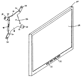
displays. An example of a flat panel display 20 that can be mounted on one of
the mounting
assemblies of the present invention is depicted in FIG. 1. Flat panel display
20 includes a
screen 22 appearing on its front side and a plurality of control buttons 24
positioned
underneath the screen. Flat panel display 20 has a thickness that is
substantially less than
conventional cathode ray tube displays. As one example, the thickness of flat
panel display
may be approximately 1 inch. It will be understood, of course, that the size,
construction,
and details of flat panel display 20 can vary from that illustrated in FIG.1.
In fact, the present
invention contemplates no limit an the size, shape, or overall construction of
the flat panel
20 displays that may be mounted on the mounting assemblies described herein.
A mounting plate 26 is also depicted in FIG. 1. Mounting plate26 attaches to
the
back side of flat panel display 20. Thus, mounting plate 26 attaches to the
side of display 20
opposite screen 22. Mounting plate 26 includes four outer apertures 28 and
four inner
apertures 30. The four outer apertures 28 are arranged generally at the four
corners of an
imaginary square. Similarly, the four inner apertures 30 are also generally
arranged at the
corners of an imaginary square. The imaginary square defined by inner
apertures 30 is
smaller than that defined by outer apertures 28. Apertures 28 and 30 are used
to mount
mounting plate 26 to the back side of display 20. Screws, or other suitable
fasteners, are
inserted into apertures 28 or 30 and into the back of display 20. Conventional
flat panel
displays typically include four screw holes positioned on their back side that
allow a mount to
be attached thereto. The screw holes are typically arranged to define a square
having one of
two different sizes. One of these sizes may have sides of approximately ten
centimeters,
although other sizes are contemplated by the invention. By including both
outer apertures 28
6
CA 02464818 2004-04-21
and inner apertures 30 in mounting plate 26, mounting plate 26 can be attached
to displays 20
having either of the two main configurations of screw holes on their back
side. Mounting
plate 26 can therefore be used with virtually all conventional flat panel
displays.
After mounting plate 26 is screwed onto the back of the display 20, the
mounting
plate 26 is typically never removed therefrom. The mounting plate 26 can be
selectively
coupled to a joint mounted to a wall, a standard, an articulating arm, or a
pole in a manner
that will be described in more detail herein. The attachment of mounting plate
26 to these
various structures can be accomplished in an easy, snap-fitting manner that
facilitates both
attachment and detachment of the display from the mount.
A mounting assembly 32 according to one aspect of the present invention is
depicted
in FIG. 2. Mounting assembly 32 is specifically adapted to allow a flat panel
display to be
mounted on a wall, or other flat surface. Mounting assembly 32 includes a
variety of
components that are depicted in more detail in FIGS. 3 and 4. With specific
reference to FIG.
4, mounting assembly 32 includes mounting plate 26, a joint 34, and a wall or
flat mount
bracket 36. Joint 34 further includes a support plate 38, a ball 40, and a
socket 42. Mounting
plate 26 further includes a pair of locking arms 44 which are illustrated in
FIG. 4 as being
detached from mounting plate 26. Locking arms 44 are, however, actually
pivotably attached
to mounting plate 26. Specifically, each locking arm 44 includes a pin 46 that
fits through a
pivot aperture 48 defined in mounting plate 26. This attachment is illustrated
in FIGS. 7 and
9-10.
Wall or flat mount bracket 36 is adapted to be attached to a flat surface such
as a wall.
Bracket 36 includes an upper mounting aperture 50 and a lower mounting
aperture 52.
Mounting apertures 50 and 52 each receive a screw that passes through bracket
36 and into a
wall or other flat surface. When mounted to a wall, the screws or other
fasteners inserted
through apertures 50 and 52 are oriented generally horizontally. Bracket 36
further includes
a pin aperture 54. Pin aperture 54 is adapted to revive a pin 56. When pin 56
is received in
pin aperture 54, pin 56 is oriented generally perpendicular to the screws that
pass through
apertures 50 and 52. Stated alternatively, when bracket 36 is attached to a
wall, pin 56 will
be in a vertical orientation. Pin 56 may include a knurled outer surface that
allows it to be
frictionally secured in pin aperture 54.
Socket 42 includes an upper half 58 and a lower half 60. Each half 58 and 60
includes a spherical portion 62 which receives ball 40. Upper and lower halves
58 and 60 are
secured together by way of a pair of bolts 64 and nuts 66. Before these halves
are secured
7
CA 02464818 2004-04-21
together, ball 40 is positioned in spherical portions 62. Thereafter, nuts and
bolts 66 and 64
are tightened so that upper and lower halves 58 and 60 are secured to each
other. The
tightening of the nuts and bolts 66 and 64 takes place after ball 40 has been
moved to a
desired orientation. The tightening via the nuts and bolts maintains the ball
in this desired
orientation. If a new orientation is desired, bolts 64 are loosened
sufficiently to allow ball 40
to rotate to the desired orientation in spherical portion 62. Thereafter,
bolts 64 are again
tightened to clamp down and hold ball 40 in the desired orientation.
Socket 42 further includes a pin aperture 68 in both upper and lower halves 58
and 60.
Pin apertures 68 in each of these halves are vertically aligned with each
other. Pin apertures
68 receive pin 56 of wall mount bracket 36. Pin S6 thereby secures socket 42
to wall mount
bracket 36. As mentioned, pin 56 may be maintained in pin aperture 54 on
bracket 36 by way
of a frictional fit. Thus, once pin 56 is inserted into aperture 54, it is
difficult, if not
impossible to remove therefrom. Pin 56 could alternatively be constructed to
include threads,
or other means, that would allow it to be screwed into pin aperture 54. Such
threads, or other
means, would allow pin 56 to be easily inserted and removed from pin aperture
54. By
allowing pin 56 to be easily removed, joint 34 could be easily detached from
wall mount
bracket 36.
The size of pin aperture 68 and socket 40 are preferably slightly smaller than
the
diameter of pin 56. Further, socket 42 is preferably manufactured out of a
flexible material,
such as plastic, that flexes when pin 56 is inserted therein. This flexing
creates sufficient
friction between pin 56 and the surfaces of pin aperture 68 to maintain socket
42 in a given
orientation with respect to pin 56. Stated alternatively, pin 56 defines a
vertical pivot axis 70
about which socket 42 can rotate. The frictional engagement of pin 56 in pin
aperture 68
maintains socket 42 in whatever orientation it has been pivoted to with
respect to pin 56.
This pivoting allows the orientation of the monitor attached to mounting
assembly 32 to be
adjusted about a vertical axis. As an alternative to sizing pin 52 larger than
aperture 68, the
external surface of pin 56 that contacts aperture 68 could be knurled or
roughened in order to
provide sufficient frictional engagement.
The position of flat panel display 20 can also be adjusted by way of the ball
and
socket joint defined by ball 40 and socket 42. Ball 40 can be adjusted about a
vertical axis
and two mutually orthogonal horizontal axes while in socket 42. Once ball 40
has been
moved to the desired orientation, nuts and bolts 66 and 64 are tightened to
maintain the
display 20 in the desired orientation. Ball 40 includes a fastener aperture 72
that receives a
CA 02464818 2004-04-21
fastener, such as a screw 74 (FIGS. 3-4). Screw 74 passes through a fastener
aperture 76 in
support plate 38 before it is inserted into fastener aperture 72 and secured
therein. Thus,
screw 74 secures support plate 38 to ball 40. A keyway 73 is defined on ball
40 and receives
a key projection 75, that projects outwardly from the back side of mounting
plate 38, when
the two are secured together by screw 74. This interaction of the keyway 73
and key
projection 75 helps prevent any unintentional rotation or slippage between
mounting plate 38
and ball 40.
As illustrated in FIGS. 3 and 4, support plate 38 is generally trapezoidal
shaped.
Support plate 38 includes two upper side surfaces 78 which are positioned
above a pair of
notches 80 defined in the side surfaces of support plate 38. Notches 80
selectively receive
protrusions 82 defined on locking arms 44. When protrusions 82 are positioned
on notches
80, mounting plate 26 is secured to support plate 38. This locking of mounting
plate 26 to
support plate 38 will now be described in more detail, particularly
withreference to FIGS. 7-
10.
As illustrated generally in FIG. 7, the back side of mounting plate 26
includes a pair
of bent flanges 84 on each side of mounting plate 26. Bent flanges 84
generally define a
sleeve 86 on the back side of mounting plate 26. Sleeve 86 is generally shaped
so that it
tapers from a wide bottom end 88 toward a narrow top end 90 of mounting plate
26. This
tapering generally matches the tapering of the side walls of support plate 38.
Thus, when
mounting plate 26 is moved downwardly in a direction 92 (FIG. 7), support
plate 38 will fit
into sleeve 86. Because of the tapered nature of sleeve 86 and support plate
38, mounting
plate 26 will be prevented from moving downwardly in direction 92 past support
plate 38.
Stated alternatively, the distance between bent flanges 84 adjacent top end 90
of mounting
plate 26 is narrower than the width of support plate 38. Thus, when mounting
plate 26 is
moved downwardly in direction 92, it will come to rest on support plate 38
when contact is
made between the side walls of support plate 38 and the inside of sleeves 86.
This resting
position is illustrated in FIG. 9.
In the resting position depicted in FIG. 9, mounting plate 26 is maintained on
support
plate 38 by way of gravity. In other words, mounting plate 26 is prevented
from being
removed from support plate 38 other than by manual lifting of mounting plate
26 off of
support plate 38. Mounting plate 26 is prevented from being moved toward or
away from
support plate 38 by the depth of sleeve 86. Specifically, the depth of sleeve
86 is
dimensioned to generally be the same as the thickness of support plate 38.
Thus, when
9
CA 02464818 2004-04-21
support plate 38 is received in sleeve 86; mounting plate 26 has little or no
wiggle room.
Mounting plate 26 can therefore not be moved toward or away from support plate
38 when in
the position illustrated in FIG. 9.
In order to lock mounting plate 26 to support plate 38, locking arms 44 are
pivoted
about pivot axes 94 (FIG. 9). Pivot axes 94 as defined generally through pivot
apertures 48
on mounting plate 26. When locking arms 44 are pivoted toward support plate
38,
protrusions 82 fit through slots 96 defined in bent flanges 84 (FIG. 7). As
locking arms 44
continue to pivot towards support plate 38, protrusions 82 pass completely
through slots 96
and into notches 80 of support plate 38. When protrusions 82 are positioned in
notches 80,
mounting plate 26 is prevented from being lifted off of support plate 38. In
order to maintain
locking arms 44 in this position, each locking arm includes a shoulder 98
positioned on an
upper, flexible latch portion 100 of locking arrn 44 (FIGS. 7 8). Flexible
latch portion 100
includes an angled surface 102 that abuts against an edge 104 at the top end
of bent flange 84
(FIG. 8) as locking arm 44 is moved to the locking position. When angled
surface 102
contacts edge 104, the angled nature of surface 102 causes edge 104 to exert
an upward force
on flexible latch portion 100. This causes flexible latch portion 100 to bend
or flex
sufficiently to allow the bottom of flexible latch portion 100 to overcome
edge 104. As the
bottom of flexible latch portion 100 continues to move toward bent flange 84,
shoulder 98
eventually reaches a locking edge 106 defined on bent flange 84. When shoulder
98 riches
locking edge 106, flexible latch portion 100 snaps back to its unflexed
position. The
engagement of shoulder 98 with locking edge 106 prevents locking arms 44 from
pivoting
about pivot axis 94. This locking position is illustrated in FIG. 10. In this
position,
protrusions 82 are inserted into notches 80 and mounting plate 26 cannot be
removed from
support plate 38. The flexing of shoulders 98 into locking edges 106 thus
provides a snap-
fitting manner of securing mounting plate 26 to support plate 38. hocking arms
44 are
preferably made out of a plastic resin or other suitable material that
generates the desired
amount of flexibility for the snap-fit.
In order to remove mounting plate 26 from support plate 38, a user simply
pushes
upwardly on flexible latch portions 100. This upward force is applied with a
sufficient
magnitude to cause shoulders 98 to flex out of engagement with locking edges
106. After
this disengagement, locking arms 44 can be pivoted about pivot axes 94 such
that protrusions
82 retreat out of notches 80. Thereafter, mounting plate 26 is lifted upwardly
off of support
plate 38. The attachment and detachment of mounting plate 26 to support plate
38 can
CA 02464818 2004-04-21
therefore be accomplished in a simple, snap-fitting manner in which no
separate fasteners
need to be tightened or used to secure the two parts together. It will of
course be understood
that the securement of support plate 38 to mounting plate 26 could be earned
out in a reverse
fashion from that illustrated and described herein. For example, mounting
plate 26 could
simply comprise a generally trapezoidal plate which fits into a sleeve defined
on support plate
38. Further, locking arms 44 could be moved to support plate 38. Further
modifications are
also possible.
A mounting assembly 132 according to a second embodiment of the present
invention
is depicted in FIGS. 5 and 6. Mounting assembly 132, like mounting assembly
32, includes a
mounting plate 26, a support plate 38, a ball 40, a socket 42, and a wall
mount bracket 36.
'These components are all constructed and operated in the same manner that has
been
described previously. Accordingly, they will not be described again. Mounting
assembly
132 further includes an extension 108. Extension 108 fits between wall mount
bracket36 and
socket 42. Extension 108 serves to extend the mounting assembly 132 a greater
distance
away from the wall or flat surface to which it is mounted. Extension 108
includes a vertical
aperture 110 that receives a cylindrical sleeve 112. Cylindrical sleeve 112
includes an
internal diameter that is sized to provide sufficient frictional engagement
with pin 56 to
maintain extension 108's orientation about pin 56. The frictional contact
between cylindrical
sleeve 1 I2 and pin 56 is not, however, so great as to prevent extension 108
from being able to
pivot about pivot axis 70.
Extension 108 further includes an upper arm 114 and a lower arm 116. Upper arm
114 and lower arm 116 are separated from each other at their end opposite
vertical aperture
110. Lower arm 116 includes an aperture I 18 that extends vertically
completely through
lower arm 116. Aperture I 18 is adapted to receive a pin 120 that is used to
pivotably secure
extension I08 to socket 42. Specifically, pin 120 fits through pin aperture 68
inupper and
lower halves 58 and 60 of socket 42. Pin 120 may be knurled or sized slightly
greater than
the dimension of pin aperture 68 to thereby generate sufficient friction to
maintain socket 42
in whatever orientation it has been pivoted to. The top end of pin 120 is
received in a partial
aperture defined in upper arm 114 (not shown). This partial aperture does not
extend all the
way through upper arm 114, as does aperture 1 I8 through lower arm 116. Pin
120 may be
maintained in aperture I 18 by way of an interference fit. With extension 108
incorporated
into mounting assembly 132, pivoting of the mounting assembly can take place
about pivot
axis 70, the pivot axis defined by pin 120, and the mufti-directional pivoting
provided by ball
11
CA 02464818 2004-04-21
and socket 40 and 42. Mounting assembly 132 thus provides a great deal of
freedom for
positioning a flat panel display 20 when it is secured to support plate 38 of
assembly 132.
A mounting assembly 232 according to yet another embodiment of the present
invention is depicted in FIGS. 11 and 12. Mounting assembly 232 includes a
number of
components that are common to mounting assemblies 32 and 132. 'These common
components are identified by the same reference numerals, and operate in the
same manner as
previously described. Accordingly, no further description of these components
will be
provided herein. Where more than one of these common components appears in
mounting
assembly 232, a letter designation has been added to the end of the reference
number to
distinguish them from their duplicates.
In addition to the components in common with mounting assemblies 32 and 132,
mounting assembly 232 further includes an elongated plate 122. Elongated plate
122 is used
to mount up to two different mounting assemblies 32, such ~ assemblies 32a and
32b in
FIGS. 11 and 12. Alternatively, elongated plate 122 could be used to mount up
to two
mounting assemblies 132. Still further, elongated plate 122 could be used to
mount one
mounting assembly 32 and one mounting assembly 132. Elongated plate 122
includes a first
mounting area 124, a second mounting area 126, and a central mounting area
128. First and
second mounting areas 124 and 126 define locations to which mounting
assemblies 32 and
132 can be attached. Each mounting area 124 and 126 includes four fastener
holes 130a-d.
Fastener holes 130a and 130b each receive a screw 132, or other suitable
fastener, which fits
through upper and lower mounting apertures SO and 52 on mounting assembly 32
or 132.
Each screw 132 also is received in a nut 134 that can be used to tighten the
attachment of
mounting assembly 32 or 132 to elongated plate 122. In addition to the general
horizontal
orientation of elongated plate 122 depicted in FIG. 1 l, elongated plate 122
can also be used
in a vertical orientation, such as that illustrated in FIG. 12. When elongated
plate 122 is
positioned in this vertical orientation, fastener holes 130c and d receive
screws 132 in order
to secure mounting assembly 32 or 132 to the elongated plate 122.
In both FIGS. 11 and 12, an additional mounting plate 26c (illustrated in
dashed lines)
is preferably attached to central mounting area 128 by way of additional
screws 132 and nuts
134. The screws 132 fit through four central fastener holes 136. From central
fastener holes
136, screws 132 further fit through outer apertures 28 in mounting plate 26c.
Because central
fastener holes 136 and outer apertures 28 are each positioned at the vertex of
a square,
elongated plate 122 can be attached to mounting plate 26 in either the
horizontal orientation
12
CA 02464818 2004-04-21
(FIG. 11) or the vertical orientation (FIG. 12). In either case, the same
central fastener holes
136 are used to secure elongated plate 122 to mounting plate 26c. Mounting
plate 26c can be
part of a third mounting assembly 32 (not shown), which would support
elongated plate 122
as if it were a flat panel display. The position and orientation of elongated
plate 122 could
S therefore be adjusted by way of the third mounting assembly. Alternatively,
mounting plate
26 could be attached to a mounting assembly 132 or a mounting assembly
supported on an
articulated arm, such as depicted in FIG. 13. Regardless of what mounting
plate 26c is
attached to, elongated plate 122 allows two flat panel displays 20 to be
mounted side by side
in either vertical or horizontal alignment. Because each flat panel display 20
has its own
mounting assembly 32 or 132 attached to elongated plate 122, the individual
flat panel
displays can have their orientations with respect to elongated plate 122
independently
adjusted. Further, if mounting plate 26c is attached to another mounting
assembly 32 or 132,
the overall position and orientation of elongated plate 122 can be adjusted.
A mounting assembly 332 attached to an articulated arm 140 is depicted in FIG.
13.
An exploded view of mounting assembly 332 and articulated arm 140 is
illustrated in FIG.
14. Mounting assembly 332 is the same as mounting assembly 132 with the
exception that
mounting assembly 332 does not include a wall mount bracket 36. Instead,
extension 108 of
mounting assembly 332 attaches to a knuckle 142. Knuckle 142 is part of
articulated arm
140. Knuckle 142 includes a vertical aperture 144 which receives a pin 146.
Pin 146 fits
through the cylindrical sleeve 112 of extension 108 in the same manner that
pin 56 does.
Thus, extension 108 is pivotable about a vertical axis defined by the
longitudinal extent of pin
146.
Articulated arm 140 is intended to be attached to a desktop, or worksurface,
or
another stationary structure. As illustrated, the articulated arm does not
include any means
for fastening it to a desktop. In order to fasten it to a work surface or
desktop, an additional
structure can be utilized. This additional structure can take on any
conventional or otherwise
suitable form. Moreover, the overall construction of articulated arm 140 can
vary from that
depicted in FIGS. 13 and 14. In fact, the invention contemplates mounting
extension 108 to
any type of articulated arm that includes a pin, or other structure, that
allows extension 108 to
be attached thereto. Articulating arm 140 could even have its stationary end
mounted to a
wall or a ceiling if desired.
As illustrated, articulated arm 140 includes a main arm 148 surrounded by
first and
second arms 150a and b. An upper pivot aperture 152 of main arm 148 receives a
pair of
13
CA 02464818 2004-04-21
pivot pins 154 that are inserted through an upper aperture 156 on knuckle 142.
This
attachment of knuckle 142 to main arm 148 via pivot pins 154 allows knuckle
142 to pivot
with respect to main arm 148 about the axis defined by pivot pins 154. Knuckle
142 further
includes a lower pivot aperture 158. Lower pivot aperture 15$ receives a pair
of pivot pins
154 that also pass through upper pivot apertures 160 defined on first and
second arms 1 SOa
and b. Thus, knuckle 142 can pivot with respect to first and second arms I SOa
and b about
the pivot axis defined by these pivot pins. Main arm 148 and first and second
arms 150a and
b are attached at their lower end to a post 162. Post 162 includes an upper
pivot aperture 164
and a lower pivot aperture 166. Upper pivot aperture 164 receives a pair of
pivot pins 154
that pass through a lower pivot aperture 168 of main arm 148. Lower pivot
apertures 166
receive a pair of pivot pins I 54 that pass through Lower pivot apertures 170
of first and
second arms 150a and b. A piston (not shown) may be included within post 162
to help
maintain articulated arm 140 in any desired orientation. A bolt 172 and a
plurality of washers
174 may also be included for securing post 162 to any additional structure
necessary to
mount it on a desktop. A cable support 1?6 may also be attached to main arm
148 to conceal
and support cables running to the flat panel display 20.
In addition to the various mounting assemblies that have been discussed
herein, the
present invention contemplates a kit assembly that comprises selected
components from the
various embodiments discussed herein. Specifically, a kit according to one
aspect of the
present invention could include an articulated arm, such as arm 140, in
combination with
mounting assembly 32. A purchaser or user of such a kit would therefore have
the option of
supporting a flat panel display on either a wall or an articulated arm. If
this person desired to
mount their flat panel display on a wall, mounting assembly 32 would be used
in the manner
previously described. If the person desired to mount their flat panel display
on an articulated
arm, socket 42 of mounting assembly 32 would be secured to knuckle 132 of
articulated arm
140 via pin 146. Bracket 36 would not be used. The kit therefore provides the
user with the
option of having their display mounted on either a wall or an articulated arm.
Further, if pin
146 is adapted to be removable from vertical aperture 144, then the user can
easily switch
between the two mounting styles as desired. It will of course be understood
that the kit could
alternatively include mounting assemblies 132 or 232 in combination with
articulated arm
140. If the kit included a mounting assembly 232 and an articulated arm 140,
an additional
ball and socket joint, in an optional extension 108, and a wall mount bracket
36 could be
14
CA 02464818 2004-04-21
included to allow mounting plate 26c to be supported on either knuckle 142 or
the wall mount
bracket 36.
A mounting bracket 36' according to another aspect of the present invention is
depicted in FIG. 15. Mounring bracket 36' is adapted to support a flat panel
display assembly
on a conventional mounting standard 178. Bracket 36' includes a pair of hooks
180 that
extend out of its back surface and hook into a pair of slots 182 defined in
mounting standard
178. The particular slots 182 selected to receive hooks 180 are based upon the
desired height
at which the flat panel display assembly is to be mounted. It willbe
understood that the
particular form of the mounting standard 178 can vary substantially from that
depicted in
FIG. 15. In fact, the invention contemplates any form of mounting standards in
which one or
more hooks on the back of bracket 36' can be inserted at desired heights. Such
standards
include those customarily found on wall panels used in office environments for
defining
cubicles or other work areas. Similarly, the design and shape of hooks 180 can
be varied
substantially from that depicted in FIG. 15. Bracket 36' may be used to
support joint 34
directly, or may be used to support joint 34 via an extension 108. Bracket 36'
may also be
used to support either a single flat panel display, or an elongated plate 122
used to support
multiple flat panel displays.
A mounting assembly 432 according to another embodiment of the present
invention
is depicted in FIGS. 16-23. Mounting assembly 432 is specifically adapted to
support a flat
screen monitor on a pole, such as pole 184 depicted in FIG. 16. Pole 184 may
extend
vertically, horizontally, or at an angle. Mounting assembly 432 allows the
flat panel monitor
to be selectively secured at any position along the length of pole 184.
Mounting assembly
432 includes a variety of components that are common to the mounting
assemblies previously
described. These components are labeled with the same reference numerals. New
components are labeled with new reference numerals.
Mounting assembly 432 specifically includes a mounting plate 26 having a
plurality
of apertures 28 and 30 which can be used to either secure it directly to the
back of a flat panel
monitor, or to secure it to an elongated plate, such as elongated plate 122.
Alternatively,
apertures 28 and 39 can be used to secure mounting plate 26 to a pair of arms,
as will be
discussed in more detail below. Mounting assembly 432 further includes a pair
of locking
arms 44 that are used to selectively secure it to a joint 34 in the manner
previously described.
Joint 34 is connected to an extension 108 having upper and lower arms 114 and
116,
respectively. Extension 108 is pivotably attached to a collar 186. Collar 186
wraps around
CA 02464818 2004-04-21
pole 184 and is adapted to be frictionally secured thereto at a desired
location on pole 184.
Extension 108 is adapted to pivot with respect to collar 186 about a pivot
axis 188 that is
generally parallel to the longitudinal extent of pole 184,
Collar 186 further includes a lever arm 190 which is pivotably secured
thereto. Lever
arm 190 is pivotable with respect to collar 186 about a pivot axis 192. Pivot
axis 192 is
defined by an aperture 194 defined in lever arm 190 (FIG. 21 ). Aperture 194
receives a pin,
or other fastener, which secures it to collar 186. Lever arm 190 is pivotable
about this pin, or
other fastener. Lever arm 190 specifically pivots between a locked position
and an unlocked
position. FIG. 16 depicts lever arm 190 in the unlocked position. FIG. 17
depicts lever arm
190 in the locked position. In the locked position, collar 186 and lever arm
190 squeeze
against pole 184 with sufficient friction to prevent movement of collar 186
along the length
of pole 184. This is true regardless of whether or not pole 184 is oriented
horizontally or
vertically. If a flat screen monitor is not mounted at the proper location
along pole 184, a
user can easily change this by simply moving lever arm 190 to the unlocked
position and then
sliding collar 186 to the new, desired position. Thereafter, lever arm is
moved back to the
locked position, and collar 186 is held in that location on pole 184. Collar
186 and lever arm
190 thus provide a quick and convenient manner for mounting the mounting
assembly 432 to
pole 184,
The manner in which lever arm 190 and collar 186 selectively grip pole 184 can
best
be understood with reference to FIGS. i 9-23. Lever arm 190 includes a cam
surface I96 that
is selectively brought into frictional engagement with pole 184 when lever arm
190 is moved
to the locked position. When lever arm 190 is moved to the unlocked position,
cam surface
196 is either out of contact with pole 184, or only loosely in contact
therewith. In either case,
the loose or absent frictional engagement between cam surface 196 and pole 184
allows
collar 186 to be slid along pole 184 to any desired location. FIG. 19
illustrates lever arm I90
when it has been pivoted to the unlocked position. As illustrated, an aperture
198 defined in
collar 186, which receives pole 184, is not interrupted by lever arm 190.
However, as
illustrated in FIG. 20, which depicts lever arm 190 in the locked position,
cam surface 196
has interrupted aperture 198. Specifically, cam surface 196 has reduced the
diameter of
aperture 198 when measured in a direction that intersects cam surface 196. The
reduced
diameter of aperture 198 when lever arm 190 is in the locked position causes
collar 186 and
lever arm 190 to securely maintain a frictional grip on pole 184.
16
CA 02464818 2004-04-21
As illustrated in FIG. 20, cam surface 196 is generally curved. Specifically,
this curve
is defined as an arc of a circle. The arc preferably has a radius which is
substantially the
same as the radius of the pole 184. This creates a better frictional fit
between lever arm 190
and pole 184, thereby more securely affixing collar 186 to a given region on
pole 184. Once
lever arm 190 is moved to the locked position, the friction between it and
pole 184, as well as
the shape of lever arm 190, maintains it in the locked position until it is
manually moved to
the unlocked position. In the illustrated embodiment, collar 186 may be made
out ofa metal,
such as aluminum. Lever arm 190 may be made out of a plastic, such as a nylon
resin. Other
types of materials are, of course, also possible.
When lever arm 190 is moved to the locked position, it is maintained in this
locked
position by way of a change in the length of the radius from pivot axis 192 to
cam surface
196. This is illustrated more clearly in FIG. 22. When lever arm 190 is
rotated so that point
A is in contact with pole 184, the distance between point A and pivot axis 192
is equal to the
length of radius Rl. When point B on cam surface 196 is in contact with pole
184, radius RZ
represents the distance between pivot axis 192 and point B. When point C on
cam surface
196 is in contact with pole 184, radius R3 represents the distance between
pivot axis 192 and
point C. The three radii R~_3 are not equal. Rather, radius RZ has the
greatest dimension.
Thus, as lever arm 190 is rotated to the fully locked position, it rotates
past point B such that
a point on cam surface 196 near point C is in contact with pole 184. In this
position, lever
arm I90 is prevented from slipping out of the Locked position because of the
greater radius of
R2. Stated alternatively, in order for lever arm 190 to be rotated to the
unlocked position,
extra force must be applied to lever arm 190 in order to move past radius Rz
in the unlocking
direction. This is because the greater radius RZ causes a greater force to be
exerted against
pole 184. Thus, the shape of cam surface 196 with respect to pivot axis 192
allows lever arm
190 to be automatically maintained in the locked position. A user mast
therefore exert
additional force against lever arm 190 in the unlocking direction in order to
move lever arm
190 to the unlocked position.
Collar 186 further includes a plurality of arms 200. Arms 200 are positioned
on a side
of collar 186 and define a wire management channel 202 (FIGS. 18-20). Wire
management
channel 202 provides a structure in which cords or wires that are running to
the monitor
supported on mounting assembly 432 may be run. In addition, cords running
along the length
of pole 184 to other structures may also be contained within wire management
channel 202.
The three arms 200 allow wires to be easily threaded into wire management
channel 202, but
17
CA 02464818 2004-04-21
generally retain them in there unless manually unthreaded. Wire management
channel 202
therefore provides a structure for minimizing the clutter of wires running
along pole 184.
FIGS. 24-28 depict another embodiment of a mounting assembly 532. Mounting
assembly 532 is particularly suited for supporting flat screen monitors that
don't have a
standard screw hole configuration on their back surface. Specifically, as was
mentioned
previously, flat screen monitors often tend to have four screw holes
positioned on their back
surface. The screw holes define the four corners of a square. Quite often, but
not always, the
distance between these four screw holes is one of two different standard
dimensions. Thus,
outer apertures 28 and inner apertures 30 are positioned to accommodate either
of these two
standard distances. However, in some cases, flat screen monitors do not have
such a standard
set of screw holes. In those instances, mounting assembly 532 may be used to
mount the flat
screen monitor. Mounting assembly 532 allows flat screen monitors to be
mounted
regardless of what type of screw holes, or other mounting means, are
positioned on the
backside of the monitor.
Mounting assembly 532 includes an upper arm 204 and a lower arm 206. In
general,
upper and lower arms 204 and 206 are slidably attached to each other. This
allows the
distance D depicted in FIGS. 24 and 28 to be adjusted. The distance D
generally corresponds
to the height of the flat screen monitor which is to be mounted. Distance D is
therefore
adjusted to match this height. Thereafter, upper and lower arms 204 and 206
are secured
together in this position. This causes the flat screen monitor to be firmly
gripped. Mounting
assembly 532 can then be mounted onto any of the previously described
structures, as will be
described in more detail below.
Upper arm 204 includes two generally flat flanges 208 positioned near its
upper end
(FIG. 28). Each flat flange 208 includes an adjacent bent flange 2I0. Flat
flanges 208 are
positioned to generally contact the topside of the flat screen monitor. Bent
flanges 210 are
positioned to extend downwardly along a portion of the front of the flat
screen monitor. Bent
flanges 210 ensure that the flat screen monitor does not fall out of mounting
assembly 532.
Similarly, lower arm 206 also includes a pair of flat flanges 212, each of
which also is
positioned adjacent a bent flange 214. Flat flanges 212 generally contact the
bottom side of
the flat screen monitor. Bent flanges 214 generally engage a bottom edge of
the front of the
flat screen monitor. The distance between the front edges of bent flanges 210
and 214 is
generally preferably less than the height of the flat screen monitor. This
prevents the flat
screen monitor from falling forwardly out of mounting assembly 532.
18
CA 02464818 2004-04-21
A pair of slide tracks 216a and b are defined in upper arm 204. Slide tracks
216 are
oriented parallel to each other and extend in a vertical direction. Each slide
track 216a and b
is dimensioned sufficiently wide to receive two screws 218. The screws 218 are
received in
four screw holes 220 defined in lower arm 206 (FIGS. 24-25). Screw holes 220
are threaded
S screw holes adapted to threadedly receive the screws 218. Each of the screws
218 also pass
through the outer apertures 28 on a mounting plate 26. Mounting plate 26 is
thus secured by
screws 218 to upper and lower arms 204 and 206. When screws 218 are firmly
tightened,
upper and lower arms 204 and 206 are not free to slide with respect to each
other. Thus,
distance D is kept at a constant height. Further, mounting plate 26 is fixedly
secured to upper
and lower arms 204 and 206. When it is desired to alter the distance D, screws
218 are
loosened. This loosening allows upper and lower arms 204 and 206 to slide
withrespect to
each other, and thus change distance D. Clnce distance D has been set to a
desired magnitude,
screws 218 are then again tightened to secure arms 204 and 206 in this
position.
Mounting plate 26 in mounting assembly 532 is the same as mounting phte 26 in
the
other embodiments of the mounting assemblies described herein. Thus, it
includes a pair of
locking arms 44 which may be used to secure it to a support plate 38 in the
manner
previously described. Mounting plate 26 can thus be easily attached and
detached from a
support plate 38. The support plate 38 is preferably part of a joint 34, such
as the joints 34
that have been described herein. The joint 34 may be mounted to any of the
structures
previously describe. Thus, the joint may be mounted to a wall using wall
bracket 36, a
standard using standard bracket 36', an arm using knuckle 142, or a pole using
collar 186.
'These mountings may or may not include an extension 108, or other
intermediate structures.
As yet another alternative, mounting plate 26 of mounting assembly 532 may be
mounted to
elongated plate 122, which may in turn be mounted to any of the structures
just described.
Mounting assembly 532 thus provides a structure for mounting non-standard flat
panel
displays to wall, standards, arms, and poles.
While the present invention has been described in terms of the various
embodiments
discussed in the above specification, it will be understood by one skilled in
the art that the
present invention is not limited to these particular embodiments, but includes
any and all such
modifications that are within the spirit and scope of the present invention as
defined in the
appended claims.
19