Note: Descriptions are shown in the official language in which they were submitted.
CA 02464824 2004-04-22
PACKAGING SYSTEM FOR DISTRUBUTING AND DISPENSING
DISPOSABLE CUPS AND LIDS
Technical Field
The present invention relates generally to packaging and dispensers for
disposable cups and lids. In a preferred embodiment, the invention provides
protective packaging for an ensemble of disposable cups and their associated
lids,
wherein the cups are papexboard cups provided with foamed insulation on their
outer surface. In another embodiment, the protective sleeve is provided with a
I O pressure sensitive adhesive mount which can be removed from a wall or door
without leaving substantial pressure- sensitive adhesive residue.
Background Art
Packaging systems and dispensers for disposable cups are known in the
15 art. There is disclosed in United States Patent No. 4,520,946 to Gould et
al. a
packaging system for disposable cups. A package in accordance with the '946
patent includes two or more individual cup dispensing units, each unit having
a
carton holding a stack of nested tapered cups. Each carton of dispensing unit
is a
paperboard carton having a generally circular opening in a top wall through
which
20 the tapered cups protrude and which opening is surrounded by a series of
short
radial cuts defining yieldable tabs on the wall which permit the top most
protruding cup to be pulled through the opening. The bottom wall of the carton
is
formed with a generally circular opening either fully cut or defined by a
series of
radial cuts which permits the protruding tapered cup of a similar, adjacent
carton
25 to extend through the bottom opening into the carton to form a compact
dispensable unit package which may be shrink wrapped for shipping and display.
United States Patent No. 3,625,395 to Salazar discloses a dispenser carton
fox holding nested articles such as paper cups. The carton includes a sleeve
30 foamed of foldably interconnected panels, each of which are foldable to
define a
closure element. Each flap has a weakened line to define a removable closure
CA 02464824 2004-04-22
2
portion and a fixed closure portion. Upon removal of the removable part an
opening is created, the edge of which engages the sides of the lowermost of
the
stack of nested articles.
The following patents relate to cup dispensers and are of more general
interest. United States Patent No. 6,325,243 to Bennett discloses a device for
dispensing cups which includes a flexible sleeve for receiving a stack of
nested
cups and a dispensing member coupled thereto. United States Patent No.
5,301,802 to Nemeroff discloses a set of drinking cups provided with
individual
identifying indicia. The cups may be distributed in paper cartons (Figures 1
and
2) or in a polymer bag (Figure 3). Likewise, United States Patent No.
3,581,934
to Sciascia discloses an adjustable cup dispenser having a minimum of parts,
namely an elongated housing far receiving a stack of cups and a control sleeve
which effects a positive size adjustment for supporting the stack of cups
which
may be of varying sizes.
Despite the many options available for the distribution and dispensing of
disposable cups, existing systems do not adequately protect the product and
provide convenience of having a cup provided with its associated lid,
especially
for hot container beverage applications. Likewise, there exists a need for a
self
mounting disposable cup dispenser which can be conveniently located where the
cups are to be used.
Summary of Invention
It has been found that conventional packaging simply does not adequately
protect the lids, which are quite fragile, when provided with their associated
cups.
Indeed, recent purchases of retail PerfecTouch~ Dixie product that contains
both
lids and cups have been found to contain cracked lids that are unusable.
Cracking
is due to the weight of the case and so forth resting on the relatively
fragile lids.
There is thus provided in accordance with the present invention a two section
cardboard tube such as are used in containers or on a tissue core which would
CA 02464824 2004-04-22
3
house the majority of the product. The lower portion of one cup would protrude
from the lower section of the tube so that consumer could touch the highly
tactile
insulation layer of the PerfecTouch~ disposable cup product. A cardboard disk
may be used to separate the two sections of the tube. Above the cups and the
disk
in the upper tube would be the lids which rest just below the upper edge of
the
cupboard tube. A clear plastic sleeve covers the entire tube, except in some
embodiments a portion of the cup that is sticking out of the tube and
optionally
the top of the tube. The plastic sleeve has, for example, a tear strip in a
circle at
the top of the tube that may be removed and provide a dispensing mechanism for
the lids. The tube itself may also have a tear strip at the top to make
dispensing
easier. A plastic sleeve or envelope may also have a tear strip at the lower
edge to
allow dispensing of the cups out of the bottom of the tulbe. By tilting the
tube in
either direction, cups or lids are easily dispensed. The clear, poly envelope
allows
consumers to view the lids at the top while the cardboard tube would protect
the
I 5 relatively fragile lids from cracking under the weight of other product or
cases
stacked on top by supporting the weight on the relatively sturdy cups and the
cardboard disk.
There thus is provided in accordance with the present invention a
packaging system for distributing and dispensing disposable cups and lids
comprising:
a) a protective sleeve defining an elongated cavity having at one
end thereof a first dispensing aperture and at the other end
thereof a second dispensing aperture;
b) a nested stack of disposable lids disposed in the elongated
cavity of the protective sleeve adjacent the first dispensing
aperture of the protective sleeve;
CA 02464824 2004-04-22
4
c) a nested stack of disposable cups disposed in the elongated
cavity of the protective sleeve adjacent the second dispensing
aperture of the protective sleeve disposed such that a lower
portion of the outermost cup of the stack protrudes through the
second aperture;
d) a polymer film envelope secured about the protective sleeve
adapted to retain the stack of lids and the stack of cups within
the protective sleeve for distribution; and
e) optionally the polymer film envelope further comprising a first
tearable portion adjacent the first dispensing aperture and a
second tearable portion adjacent the second dispensing
aperture, the tearable portions being configured to allow for
dispensing of the lids and cups from the protective sleeve upon
rupture of the tearable portions
Typically, the protective sleeve is a cylindrical cardboard sleeve and the
film envelope is a shrink wrap envelope. The sleeve may be provided with a
tearable portion which can be removed to facilitate dispensing. In a preferred
embodiment, the stack of nested lids comprises a plurality of domed lids. The
lids
may be thermoformed or produced by any other suitable means. In some cases
the lower portion of the outermost cup protrudes through the polymer film
envelope so that it may be grasped by a consumer.
The cups may be paperboard cups if so desired and are preferably
provided with foamed polymer insulation on their outer surfaces. The foamed
insulation on the outer surface may be formed in-situ by action of moisture
present in the paperboard with a polymer film applied to the paperboard if so
desired. Alternatively, the foamed polymer insulation i.s syntactic polymer
foam.
The foamed insulation may be applied in a pattern whereby the outer surface of
CA 02464824 2004-04-22
the cup has portions with foamed polymer insulation and portions without
foamed
polymer insulation.
In a preferred embodiment, the polymer envelope is a shrink wrap
envelope and the protective sleeve has disposed therein a separator member
between the nested cups and the nested lids.
In another embodiment a packaging system for distributing and dispensing
disposable cups and lids includes a protective sleeve de:Eining an elongated
cavity
having at one end thereof a first dispensing aperture and at the other end
thereof a
second dispensing aperture. A nested stack of disposable lids is disposed in
the
elongated cavity of the protective sleeve adjacent the first dispensing
aperture of
the protective sleeve and a nested stack of disposable cups is disposed in the
elongated cavity of the protective sleeve adjacent the second dispensing
aperture
of the protective sleeve disposed such that the lower portion of the outermost
cup
of the stack protrudes through the second aperture. The protective sleeve is
provided with tab means for releasably retaining the cups within the sleeve as
well
as a polymer envelope covering the lower portion of the outermost cup of the
stack which protrudes through the second dispersing aperture. The protective
sleeve further includes a mounting portion including a pressure sensitive
adhesive
capable of securing the sleeve loaded with the cups and lids to a vertical
support
and which mounting portion is removable from the vertical support without
leaving a substantial amount of pressure sensitive adhesive residue thereon.
In still yet another embodiment there is provided a packaging system for
distributing disposable cups including:
a) a protective sleeve defining an elongated cavity as well as a sleeve
opening;
b) a nested stack of disposable cups disposed in the elongated cavity;
CA 02464824 2004-04-22
6
c) tab means about the sleeve opening configured to releasably retain the
stack of nested cups within the sleeve; and
d) means for mounting the sleeve on a vertical support, including a
pressure- sensitive adhesive capable of secuz~ing the sleeve loaded with
cups to the vertical support and which mounting portion is removable
from the vertical support without leaving a substantial amount of
pressure- sensitive adhesive residue thereon.
Preferably the means for mounting the sleeve includes a polymeric
adhesive tape having a length-wise elongation at break of from about 50% to
about 1200%. That tape may be a foamed polymeric tape having a thickness of at
least about 30 mils or so. Typically, the tape has a Young's rnodulus of less
than
about 2400 psi.
The tape includes a polymeric backing material selected from
polyethylene, including high density polyethylene; low density polyethylene,
linear low density polyethylene, and linear ultra-low density polyethylene;
polypropylene and polybutylenes; polyvinyl chlorides, both plasticized and
unplasticized; and polyvinyl acetates; ethylene methac~ylate copolymers;
ethylene/vinyl acetate copolymers; acrylonitrile-butadiene-styrene copolymers,
and ethylene/propylene copolymers; acrylic polymers and copolymers;
polyurethanes; and combinations of the foregoing.
So also the pressure-sensitive adhesive on the tape backing is preferably
selected from natural rubber; olefins; silicones; polybutadienes; styrene-
isoprene-
styrene; styrene-ethylene-butylene-styrene; styrene-butadiene-styrene block
copolymers; as well as copolymers of isooctylacrylate and acrylic acid.
CA 02464824 2004-04-22
7
The tab means of the disposable dispensers includes a plurality of tabs in
some embodiments projecting inwardly from the sleeve wall to define a cup
dispensing aperture. In some cases, the tabs have different lengths. The tabs
may
be integrally formed with the protective sleeve or disposed on an annular
support
affixed to the protective sleeve as is described hereinafter. The protective
sleeve
may be a polymeric blow molded protective sleeve or in some cases a paperboard
(chip board) protective sleeve. Further details will became apparent from the
following description, drawings and claims.
Brief Description of Drawings
The invention is described in detail below with reference to the various
Figures wherein like numbers designate similar parts anal wherein:
Figure 1 is a view in perspective of a first embodiment of the packaging
system of the present invention;
Figure 2 is a view in elevation and partial section of the packaging system
of Figure 1;
Figure 3 is a view in perspective of a second eiribodiment of the
packaging system of the present invention;
Figure 4 is a view in elevation and section of the embodiment of Figure
3;
Figures 5 and 6 are views in elevation and section of disposable cups
which may be used in connection with the packaging system of the present
invention;
CA 02464824 2004-04-22
8
Figure 7 is a schematic view showing an alternate embodiment of the
present invention wherein a strip of paperboard is used to form a protective
sleeve
for the lids only in a package of cups and associated lids;
Figure 8 is a view in perspective of another packaging system and
dispenser in accordance with the present invention;
Figure 9 is a bottom view of the dispenser of Figure 8;
Figure 10 is a schematic detail showing the mounting of the dispenser of
Figures 8 and 9 to a vertical wall;
Figure 11 is a plan view of a dispensing ring which may be attached to a
protective sleeve of the packaging system of the present; invention; and .
Figure 12 is a view in perspective of yet another packaging system of the
present invention.
Detailed Description
The invention is described in detail below with reference to the various
figures for purposes of exemplification and illustration only. Modifications
within the spirit and scope of the present invention will be readily apparent
to
those of skill in the art. The present invention is defined in the appended
claims.
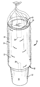
Referring to Figures 1 and 2 there is shown a first embodiment of the
inventive packaging system 10 which is used for distributing and dispensing
cups
and lids. The packaging system is particularly suitable .for beverage cups
adapted
to receive hot beverages such as coffee, tea and the like., wherein it is
often
desirable to have an associated lid, but is suitable for an,y cup with a
fragile lid.
CA 02464824 2004-04-22
9
In Figures 1 and 2 there is shown a packaging system 10 including a
protective sleeve 12 having an elongated central cavity 14 and defining a
first
dispensing aperture 16 as well as a second dispensing aperture 18.
The sleeve may be formed of cardboard or the like, or any other suitable
material which will protect the lids from being crushed. A preferred
construction
of the sleeve may be from a wound and adhered sheet of cardboard of the
general
class used for tubular packaging and/or used as cores for tissue or towel.
Such
construction is well known in the art.
A nested stack of disposable lids 20 is disposed in the central cavity
adjacent first dispensing aperture 16. Likewise, a nested stack of disposable
cups
22 is disposed adjacent second dispensing aperture 18 of sleeve 12. A polymer
envelope 24 is secured about the sleeve and the cups and lids in order to
retain
them within the protective sleeve 12, the lower portion of the outermost cup
indicated at 30 protrudes through second dispensing apf;rture 18 so that it
may be
readily grasped by user. Cups with particularly pleasing tactile properties
are
preferred such as the PerfecTouch~ cups sold by Georgia-Pacific Corporation,
Dixie Division. The polymer envelope has a first tearable portion 26 defined
by a
perforated perimeter as well as a second tearable portion 28 defined by
another
perforated perimeter about the terminal portions of protective sleeve 12. The
tearable portions are removed when it is desired to remove a cup and/or lid
from
the packaging system. So also, the dashed lines at 26 may designate a tear
strip
defined in sleeve 12 by perforations, which tear strip can be removed to
facilitate
dispensing.
If so desired, the packaging system may be tilted one way or the other to
facilitate dispensing of the articles. In preferred embodiments the polymer
film
envelope is a shrink wrap envelope and the nested stack of lids are domed lids
which may be produced, for example, by thermoforming.
CA 02464824 2004-04-22
In some cases lower portion 30 of the outermost cup protrudes through the
polymer film so that the lower portion thereof is available to a consumer. The
cups are preferably paperboard cups provided with foamed polymer insulation on
their outer surfaces as will be described hereinafter.
In Figures 3 and 4 there is shown another embodiment of the inventive
packaging system. Packaging system 110 includes a sleeve 112 defining a cavity
114. Sleeve 114 also defines a first dispensing aperture 116 and a second
dispensing aperture 118. A nested stack of disposable lids 120 is disposed
10 adjacent first dispensing aperture 116 and a nested stack of disposable
cups 122 is
disposed adjacent second dispensing aperture 118. Between the nested stacks of
lids and cups there is provided a cardboard disk 121 which serves to separate
the
respective stacks. A polymer film envelope 124 is formed of shrink wrap and
has
a first, upper tearable portion 126 having a generally circular perimeter
defined by
perforations and a lower second tearable portion 128 also having a perimeter
defined by perforations. The lower portion 130 of the outermost cup protrudes
downwardly through the second dispensing aperture of sleeve 112 and through
polymer envelope 124 as described in connection with similar parts of the
embodiment of Figures l and 2.
There is thus provided in accordance with the present invention a
packaging system which provides for the convenient dispensing of cups and
their
associated lids without the need for multiple dispensing systems. Moreover the
lids are protected by the protective sleeves from breakage during shipping and
handling which has been found to be particularly troublesome with respect to
small quantities of lids. Separator disk I21 prevents unwanted movement of
product when the dispenser is tipped. If so desired disk. I21 can be secured
at 132
to sleeve 112.
While the inventive packaging system can-be used in connection with a
variety of cups and their associated lids, the dispenser and packaging system
of
the present invention is particularly preferred for paperboard cups adapted
for hot
CA 02464824 2004-04-22
11
beverages having on their outer surface foamed polymer insulation. Suitable
foamed polymer insulation material is described in co-pending patent
application
United States Serial Nos. 09/018,563 and 10/36,347, both of Swoboda et al. and
both entitled "Coated Paperboards and Paperboard Containers Having Improved
Tactile and Bulk Insulation Properties, Attorney Docket Nos. 1935-1 and 1935-
2,
filed February 4, 1998 and September 6, 2002, respectively, the disclosures of
which are incorporated herein by reference. Suitable foamed insulation applied
to
the paperboard cups of the inventive packaging system also include those
foamed
insulation materials described in United States Patent Nos. 5,766,709;
5,759,624;
5,725,916; 5,415,340; 5,490,631; 5,278,194; 4,902,722; 4,435,344; 4,425,449;
4,237,171; and 3,864,181. The disclosures ofthe foregoing applications and
listed United States patents is hereby incorporated by reference. Particularly
suitable paperboard cups with foam insulation layers are disclosed in United
States Patent Nos. 5,576,709 and 4,435,344. In these patents a foam insulation
layer is produced by foaming a polymer material in-situ on the outer surface
of a
paper cup. In the'709 patent the thickness of the foam layer is controlled by
printing, or application of mineral oil to the surface of the polyxiier film.
In Unites
Patent No. 4,435,344 of lioka et al. the foam is produced in-situ by action of
the
moisture present in the paperboard with a polymer film applied to the outer
surface of the paperboard. So also, it will be appreciated from the foregoing
patents and applications that syntactic foams are readily applied to the outer
surface of paperboard used to make the cups utilized in connection with the
invention as will be appreciated from United States Patent No. 4,902,722 to
Melber. Such foams can be applied over the entire surface of the side wall of
the
cups or may be applied in a printed pattern as will be appreciated by
reference to
Figures 5 and 6 hereof. The terminology "syntactic foam" refers generally to a
quasi-foam formed by insulating particles and a polymeric binder. The
particles
may be hollow microspheres, for example, or simply a particulate material with
relatively low thermal conductivity.
CA 02464824 2004-04-22
12
Referring to Figure 5 there is shown a cup 210 provided with a sidewall
212 and a bottom wall 214. About its upper periphery the cup 210 has a brim
216. Sidewall 212 is formed of a paper or a paperboard layer 218 having coated
on its inner surface an impermeable film 220. The film is preferably formed of
a
high density polymer material and is impervious to moisture. Additionally
bottom
wall 214 includes a paper or paperboard layer 222 having formed thereon a
moisture impervious film 224. The outer surface of paperboard Iayer 2I8 is
coated with a low density synthetic resin film 226 on its surface. This low
density
film of plastic synthetic resin film 226 when heated expands to form a heat
insulating foam as will be appreciated from the aforesaid United States Patent
No.
5,766,709. It has further been found that by applying a mineral oiI film 242
on the
film of plastic resin film 226 the expansion of the thermoplastic and
synthetic film
when heat treated is enhanced.
Refernng to Figure 6, there is shown a pattern 310 of printed syntactic
foam material arranged in continuous longitudinal lines 312 as well as a
plurality
of segments 314. It is thus defined on a paperboard surface portions which are
coated such as at 314 and 312 and unfoamed regions indicated at 316. Such
insulated surfaces for hot beverage cups are contemplated within the spirit
and
scope of the present invention which is defined in the appended claims.
Referring to Figure 7, there is shown schematically another embodiment
of the present invention wherein there is provided a protective sleeve 320
formed
from a strip of paperboard 322 which is optionally j oined to itself by
adhesive
indicated at 324 and optionally provided with die-cut tabs 328, 330 adapted to
hold a plurality 332 of nestable thermoformed lids. Each lid, such as lid 334
has a
domed shape including a lid top 336 and sidewall 338. The lids have an overall
diameter, D, of about 33/4 inches in some embodiments and an overall height,
H,
of about 3/< of an inch. Preferably, the lids are thermoformed lids and have a
height of at least about 10% of the lid diameter, with at least about 15% or
20%
CA 02464824 2004-04-22
13
being even more preferred, even though the sidewall may make the lids more
fragile than flat lids.
The sleeve has a height, H', which is larger than the height of a single lid
by 1/4 to 1 inch so that it can accommodate a plurality of lids, which are
placed
within the sleeve. The cups are generally less fragile than the lids, so that
sleeve
320 is conveniently substituted for sleeve 12 of Figure 1 or sleeve 112 of
Figure
3; especially when cup damage during distribution is not a problem. Thus, the
lids are within sleeve 320, while the lids are not.
Referring to Figures 8 through 10 there is shown a dispenser 410
including a protective sleeve 412 provided with a cap 414 as well as a
mounting
portion 416. The protective sleeve is configured to accept a stack 418 of
disposable cups as shown in the diagram. Preferably, the cups protrude through
a
dispensing aperture and are covered by a polymeric envelope such as envelope
420 which may be a shrink wrap envelope if so desired. The mounting portion
has a mounting wall 422 which is perhaps better seen in Figure 10 which is an
enlarged detail of the dispenser mounted on a vertical support such as wall or
door
438. Affixed to mounting wall 422 is a first layer of adhesive 424 as well as
a
foam backing 426 which has the characteristics described below. On the backing
is a pressure-sensitive adhesive layer 428 as well as a release layer 430
which
covers the pressure-sensitive adhesive during shipping of the container, that
is,
until it is ready to use.
Layer 424 secures backing 426 to wall 422 of the dispenser. At the
bottom of dispenser 410 is a dispensing aperture 432 which has a plurality of
tabs,
such as tabs 434 and 436 that project inwardly from the walls of sleeve 412 to
define the dispensing aperture as shown.
The protective sleeve is made by extrusion blow-molding as is well known
and seen, for example, in United States Patent Nos. 6,312,248 to Lopez et al.
and
4,549,977 to Joshi et al. The dispensing tab such as tabs 434 and 436 may be
CA 02464824 2004-04-22
14
integrally formed with protective sleeve 412 or may be carried on a
thermoformed
or injection molded disk.
A blow-molded protective sleeve may be made of any suitable material
such as polyethylene terephthalate or other thermoplastic. Suitable materials
may
include: polystyrene; polycarbonate; styrene; acrylonitrile; polyvinyl
chloride;
polyolefm polymers including polypropylene, cyclic polyolefm copolymers,
polyethylene, polybutylene polymers and the like; polyamide polyners;
polysulfones; polyacetals; polyarylates; polyacrylonitrile--stryrene
copolymers;
polyolefin ionomers; styrene-acrylonitrile copolymers; environmentally
degradable polymers and mixtures thereof.
Dispenser 410 is mounted on vertical support 438 by way of the pressure-
sensitive adhesive layer 428. An important feature of the present invention is
that
layer 428 is capable of supporting a fixlly loaded dispenser, and yet does not
leave
a substantial amount of adhesive residue when the dispenser is removed from a
wall such as wall 438. To this end, backing 426 is made from a plastic
material
which has an elongation at break of at Least 50 % and up to about 1200 %. The
tape also includes a tab or portion 440 which does not have adhesive thereon.
This tab is pulled in order to fracture the adhesive bond between Layer 428
and
wall 438 as will be appreciated from the discussion which follows. Further
details
may be found in United States Patent No. 6,231,962 to BYies et al.; United
States
Patent No. 6,001,471 also to Bries et al. as well as United States Patent No.
5,516,581 to Kreckel et al.
Elongation at break and Young's rnodulus (elastic modulus) in respect of a
tape or a backing or a polymeric layer in the backing of a tape is measured
for
purposes of the instant specification and claims following ASTM D882,
incorporated herein by reference, using an InstronTM Model 1122 Tensile Tester
(available from Instron Corporation, Canton, Mass. 02021) or other suitable
device. For elongation at break measurements, tape samples are cut to 1/z " X
4"
CA 02464824 2004-04-22
strips (I.27 cm X I0.2 cm) and the InstronTM is set for a 2-inch (5.08 cm)
gauge
length, 20 inch/minute (50.8 cm/minute) cross-head speed and 20 lb. (9. 1 kg)
full
scale load. For Young's modulus measurements, a backing or a polymeric layer
for use in a backing is cut to I/2" X 10" strips (1.27 cm X 25.4 cm) and the
InstronTM is set for an 8-inch (20.3 cm) gauge length, 1-inch/minute (2.54
cm/minute) cross-head speed and 20 lb. (9.I kg) full scale load.
Representative examples of materials suitable for either a polymeric foam
or solid polymeric film layer in the backing of the tape include polyolefins,
such
I O as polyethylene, including high density polyethylene, low density
polyethylene,
linear low density polyethylene, and linear ultra low density polyethylene,
polypropylene, and polybutylenes; vinyl copolymers, such as polyvinyl
chlorides,
both plasticized and unplasticized, and polyvinyl acetates; olefinic
copolymers,
such as ethylene/methacrylate copolymers, ethylene/vinyl acetate copolymers,
15 acrylonitrile-butadiene-styrene copolymers, and ethylene/propylene
copolymers;
acrylic polymers and copolymers; polyurethanes; and combinations of the
foregoing. Mixtures or blends of any plastic or plastic and elastomeric
materials
such as polypropylene/polyethylene, polyurethane/polyolefin,
polyurethane/polycarbonate, polyurethane/polyester, can also be used.
Polymeric foam layers for use in the backing of the .tapes generally will
have a density of about 2 to about 30 pounds per cubic foot, particularly in
tape
constructions where the foam is to be stretched to affect debonding.
Preferred for polymeric foam layers in the backing of the tapes are
polyolefin foams. Polymeric foam layers are most preferably polyolefin foams
available under the trade designations Volextra.TM. and Volara.TM. from
Valtek,
Division of Sekisui America Corporation, Lawrence, Mass. 01843.
Solid polymeric film backings are preferably selected from polyethylene
and polypropylene films, with the most preferred materials being linear low
density and ultra low density polyethylene films. A preferred polyethylene
film is
CA 02464824 2004-04-22
16
that available under the trade designation Maxilene.TM. 200 from Consolidated
Thermoplastics Company, Schaumburg, Ill. 60173.
The backing may vary in overall thickness so long as it possesses
sufficient integrity to be processable and handleable and provides the desired
performance in respect to stretching properties for debonding the backing or
tape
from a surface. The specific overall thickness selected for a backing will
depend
upon the physical properties of the polymeric foam layer or layers and any
solid
polymeric film layer forming the backing. Where only one polymeric film or
foam layer of a multi-layer backing is intended to be stretched to effect
debonding, that layer should exhibit sufficient physical properties and be of
a
sufficient thickness to achieve that objective.
A polymeric film layer preferably will be about 0.4 to 10 mils in thickness,
and will most preferably be about 0.4 to 6 mils in thickness.
The adhesive of the adhesive layer can comprise any pressure-sensitive
adhesive, with the particular adhesion properties being dependent on the use
of
the tape, with the preferred adhesion properties generally ranging from about
4
N/dm to about 200 N/dm, preferably from about 25 N/dm to bout 100 N/dm, at a
peel angle of 180°, measured according to PS'TC-l and PSTC-3 and ASTM
D 903-83 at a peel rate of 12.7 cm/min. Adhesives having higher peel adhesion
levels usually require backings having higher tensile strength.
Pressure-sensitive adhesives suitable for application to one side of the
backing and/or the other in the tapes of the invention include tackified
rubber
adhesives, such as natural rubber; olefins; silicones; synthetic rubber
adhesives
such as polyisoprene, polybutadiene, and styrene-isoprene-styrene, styrene-
ethylene-butylene-styrene and styrene-butadiene-styrene block copolymers, and
other synthetic elastomers; and tackified or untackified acrylic adhesives
such as
copolymers of isooctylacrylate and acrylic acid, which can be polymerized by
CA 02464824 2004-04-22
17
radiation, solution, suspension, or emulsion techniques. Preferred are
synthetic
rubber adhesives or acrylics.
Especially preferred adhesives inherently possess more cohesive strength
than adhesive strength to the mounting surface.
The thickness of each adhesive layer can range from about 0.6 mils to
about 40 mils (about 0.015 to about 1.0 mm), preferably from about 1 mils to
about 16 mils (about 0.025 to about 0.41 mm). In this preferred range of
thicknesses, the thicker layers tend to cause the tapes to be more easily
removable
than do thinner layers. This is in contrast to conventional methods of
removal,
such as removal by peeling at peel angles of 90° or higher. In general,
thicker layers of adhesive tend to cause the tapes to exhibit higher peel
strength at
a peel angle of 180° than do thinner layers. When the tapes of the
present
invention are released by stretching at a low angle, i.~e., under 35°,
the
adhesive tends to be constrained by the backing and substrate for a single-
coated
adhesive tape and by the backing and two substrates for a double-coated
adhesive
tape, and is forced to undergo significant elongation. Under these conditions,
the
adhesive layer (or each adhesive layer) contracts, which reduces its cross-
sectional area. Since the cross-sectional area, i.e., thickness times width,
of a
thinner layer of adhesive is already less than that of a thicker layer of
adhesive,
stress, i.e., force per unit area, is greater in the thinner layer of adhesive
than in
the thicker layer of adhesive. This leads, in effect, to a stiffening of the
adhesive.
Because stiffer layers offer mare resistance to defom~ation, the force
required for
debonding is greater. The exposed adhesive layer or layers may be laminated to
a
conventional release liner prior to use.
Adhesives for adhering one polymeric foam layer to either another
polymeric foam layer or a solid polymeric Elm layer include those pressure-
sensitive adhesive compositions described above. Preferably the adhesive layer
CA 02464824 2004-04-22
18
for adjoining one polymeric layer of the backing to another will be about 1 to
10
mils (about 0.025 to 0.25 mm) in thickness. Other methods of adhering the
polymeric layers of the backing to one another include such conventional
methods
as coextrusion or heat welding.
The tape can be produced by any conventional method for preparing
pressure-sensitive adhesive tapes. For example, the adhesive can either be
directly
coated onto the backing, or it can be formed as a separate layer and then
later
laminated to the backing.
Removing the tape from the surface of a substrate can be carried out by
simply stretching the tape.in a direction up to an angle of about 35 degrees
from
the surface. Preferably, the tape can be removed from the surface of a
substrate by
stretching the tape at an angle of no greater than about 10 degrees. Removal
at
the appropriate angle will result in leaving no substantial or appreciable
adhesive
residue and in preventing the surface of the substrate from being damaged.
Debonding of a highly elongated adhesive tape at low angles is
characterized by a "sharp" type of crack propagation.. Like fracture of glassy
materials, a sharp crack leads to high stress concentration at the crack
front, where
there is a low volume of adhesive material (in which stress may be
dissipated).
High stress concentration at the crack front leads to what is called brittle'
cleavage
failure of the adhesive. Such failure typically occurs with low force (because
of
the low amount of energy dissipated in the adhesive material) and is cleanly
interfacial.
In contrast, for higher peeling angles, i.e., angles generally greater than 35
degrees, the backing tends not to stretch and the adhesive tends to undergo
filamentation and rupture cohesively. Like fracture of glassy materials,
propagation of a "blunt" crack is preceded by crazing. In this model, the
observed
filamentation of the adhesive at higher angles serves principally as an energy
CA 02464824 2004-04-22
19
dissipation mechanism, analogous to craze fibrils found in glassy materials.
The
greater the energy dissipation, the greater the resistance to peeling and the
higher
the force required to peel the tape. A larger volume of material is involved
in
energy dissipation, and, as stated previously, stress is less concentrated.
'The
adhesive filaments rupture cohesively to leave residue of adhesive on the
surface
and/or cause damage to the surface.
There is shown in Figure 11 a dispensing ring 442 having a diameter 443
as well as tabs 444, 446, 448 and so on defining a dispensing aperture 445
corresponding to aperture 432 of Figure 8. Note that the dispensing tabs such
as
tabs 444 and 446 are of different lengths so that dispensing aperture 445 has
different dimensions 452 and 450. In other words; it: is plain from the
diagram
that because tab 446 arid its opposing tab are larger than tabs 448 and its
opposing
tab distance 450 is shorter than distance 452. Any number of tabs may be
utilized
in making the packaging system and dispenser of the invention; however,
anywhere from about 4 to about 8 tabs is believed preferred. Suitable
geometries
for the dispensing rings and/or tabs are described in co-pending United States
Patent Application No. 10/405,393, filed April 2, 2003 (Attorney Docket No.
2383; GP-O1-29), now United States Patent No.
In Figure 12 there is shown yet another packaging system configured in
accordance with the present invention.
Packaging system 510 includes a protective cardboard sleeve 512
surrounding a stack of cups 514 and includes a mounting portion 516
corresponding to mounting portion 416 described above. In the embodiment .
shown in Figure 12, protective sleeve 512 is made of chipboard and is of
rectangular shape so that the protective sleeve may be folded flat for
shipment to a
packaging center. The sleeve is provided with a dispensing ring such as ring
442
of Figure 11 as well as a polymer envelope 518 to hold the stack 514 in
position
during shipping. Polymer envelope 518 may be a shrink wrap envelope if so
CA 02464824 2004-04-22
desired. Mounting portion 516 includes the features of mounting portion 416 of
the embodiment of Figures 8 through 1~.
While the invention has been described in connection with several
examples, modifications to those examples within the spirit and scope of the
invention will be readily apparent to those of skill in the art. In view of
the
foregoing discussion, relevant knowledge in the art and references including
co-
pending applications discussed above in connection with the Background and
Detailed Description, the disclosures of which are all incorporated herein by
reference, further description is deemed unnecessary.