Note: Descriptions are shown in the official language in which they were submitted.
SP 2~2814 VD 1
IMPROVEMENT TO A METHOD AND AN TNSTRUMENT FOR
INSPECTION OF THE BOND BETWEEN A HONEYCOMB CORE AND A
SKIN
DESCRIPTION
Technical field
This invention relates to the technical domain of
laminated honeycomb structures, called '°honeycombs~~ for
short.
It is an improvement to the method and the
instrument for inspection of the bond between a
honeycomb core and a skin, as defined in patent FR 2
785 388.
Remember that at one stage of manufacturing, a
honeycomb is composed of a honeycomb core bonded to a
skin on one of its ends. The honeycomb core is in the
form of adjacent cells separated by partitions
extending through the direction of the thickness of the
honeycomb. The bond between the honeycomb core and the
skin may be made by welding, gluing or brazing. Bond
defects may occasionally occur. These defects may be
isolated defects or they may be in the form of complete
areas of defects. They result in the occurrence of
spaces between the partitions of cells and the skin,
that put the cells into communication with each other.
State of prior art
It is required to inspect the quality of the bond
between. the partition cells and the skin, and to detect
defects in this bond.
CA 02465390 2004-04-28
SP 22814 VD 2
The method and the instrument used for inspection
of the bond between a honeycomb core and a skin as
divulged in patent FR 2 785 388 will be briefly
described, with reference to figure 1.
Figure 1 shows a honeycomb 1 comprising a
honeycomb core 3 composed of adjacent cells 5 delimited
laterally by partitions 7, said core 3 being bonded on
one side on a skin 2, while at this stage of
manufacturing the other side forms a free surface 4 on
which the openings 6 of said cells 5 are located.
The inspection method according to prior art
includes the (allowing operations:
- use a light source 15 to illuminate a so-called
illuminated area 17 on the free surface 4 of the
honeycomb 1, in order to illuminate the inside
of the cells 5 opening up in said illuminated
area 17,
- detect emerging light 21 output .from the cells 5
in a so-called observed area 22 also at said
free surface 4.
The inspection instrument 60 according to prior
art is specially designed to implement said inspection
method. It comprises:
a) a mask 26 delimited laterally by an
illumination edge 27 and an observation edge 28
opposite said illumination edge 27,
b) a light source 15, placed behind the mask 25,
said light source 15 being fixed to the mask 26
and producing an incident light beam 16 from
the back of the mask 26 towards the front of
the mask 26,
CA 02465390 2004-04-28
SP X2$14 VD 3
c) means 20 of detecting and signaling any light
21 emerging from the back of the mask 26
towards the front, said detection means 20
being fixed to the mask 2E, said emerging light
21 passing in front of the observation edge 28.
The mask 26 is placed in contact with the free
surface of the honeycomb or in th.e vicinity of it. A
screen 29 may be fixed above it located between the
light source 15 and the detection means 20. The mask
26 covers an intermediate area 25 of the free surface
4, located between the illuminated area 17 and the
observed area 22. The mask 26 moves along a direction
D, and performs an incremental or continuous scanning
so as to pass above all the cells 5. The minimum
distance between the illuminated area 17 and the
observed area 22 is denoted E. It is equal to at least
the width L1 of the openings 6, said width L1 being
measured along the direction D.
The detection means may be simply an operator's
eye. Alternately, automated detection means could be
used capable of picking up a signal from light 21
emerging from incident light 16. These detection means
may be associated with display means capable of
reproducing an optical image of the picked up signal.
Figure 2 illustrates such an optical image obtained
after scanning of the mask.
A spot 80 Corresponding to a bond defect appears
on the optical image. It is located between a line 27a
that is an image of the illumination edge 27 of mask
26, and a line 28a that is an image of the observation
edge 28 of the mask 26. The distance AB between the
CA 02465390 2004-04-28
SP 22814 VD 4
two lines 27a and 28a is minimum and is equal to the
distance E.
The previous device has a disadvantage in that
during displacement, the mask rubs against the
honeycomb core at the openings of the cells due to
irregularities existing on the free surface at this
stage of manufacturing. Friction. induces two harmful
consequences; the first consequence of this friction
is damage to the free surface and consequently an
1Q alteration to the qualities of the honeycomb. The
second consequence of this friction is a disturbance to
displacement of the mask and consequently an alteration
to the performances of the method of inspecting' the
bond between the honeycomb core and the skin.
A solution has been provided for this
disadvantage, through a variant of the inspection
method according to prior art. This variant is
illustrated in figure 3 and consists of lifting said
mask 26 to a certain height H above the free surf ace 4.
Thus, the mask no longer rubs in contact with said free
surface as it moves.
If emerging light is detected by the operat.or's
eyes, this variant in the inspection method is
satisfactory.
However, if emerging light is detected by
automated means, for example such as a CCD camera
associated with automatic processing means for the
emerging light signal, then this variant of the
inspection method according to prior art has a new
disadvantage. Since the mask is lifted, the detection
means can detect a signal corresponding to the emerging
CA 02465390 2004-04-28
SP 22814 VD 5
light 21 representative of a defect 50 in the bond
between the honeycomb core and the skin, but also one
or several additional signals corresponding to one or
several parasite reflections 18 due to the reflection
of the incident light 16 on the tap edges of the
partitions 7 separating the cells 5. Figure 4 shows an
optical image illustrating this disadvantage. The spot
80 corresponds to a bond defect 80, while spots 90
correspond to parasite reflections 18. The result is
that the inspection of the bond between the honeycomb
core and the skin is not reliable, since a light signal
can be detected that does not correspond to a defect in
the bond between the honeycomb core and the skin.
Summary of the invention
The purpose of this invention is to overcome the
disadvantages mentioned above.
It proposes an inspection method and an inspection
instrument that solve the problem of friction of the
mask on the honeycomb and the problem of identification
of light signals picked up by automated detection
means.
According to the invention, the method for
inspection of the bond between a honeycomb core and a
skin, in which said honeycomb comprises a honeycomb
core composed of adjacent cells delimited laterally by
partitions, said core being bonded onto a skin at one
side, while at this stage of manufacturing the other
side forms a free surface containing the openings of
said cells, comprises the following operations:
CA 02465390 2004-04-28
SP X2814 VD 6
- use of a light source to illuminate a so-called
illuminated area on the free surface of the
honeycomb, in order to illuminate the inside of
cells opening up in said illuminated area,
- automatically detect emerging light from the
cells in a so-called observed area also at said
free surface,
the minimum distance between said illuminated area
and said observed area being denoted E and defining a
direction D, and the distance E being equal to at least
the width L1 of the openings, said width L1 being taken
along the direction D.
The inspection method also comprises the operation
consisting of:
- automatically detecting openings in a so-called
photographed area also at said free surface.
Preferably, the minimum distance between said
observed area and said photographed area measured along
the direction D and denoted F, is less than the width
L2 of the openings of two adjacent cells.
Preferably, the inspection method also includes
signal processing operations consisting of:
- transforming a signal carrespanding to detected
emerging light into a first optical image in the
form of a matrix of pixels on which spots appear
w representing any bond defects and spots
representing parasite reflections,
- transforming a signal corresponding to the
detected openings into a second optical image in
the form o.f a matrix of pixels on which contours
appear.
CA 02465390 2004-04-28
SP 22814 VD 7
Preferably, the inspection method also comprises
an image processing operation comprising the following
steps:
- superpose: said first optical image and. said
second optical image, and identify the spots on
the first optical image that are at least partly
superposed with the contours of the second
optical image as being spots representing
parasite reflections,
- provide a third optical image derived from the
first optical image from wYiich spots identified
as being spots representing parasite reflections
have been removed.
The inspection method comprises another optional
image processing operation consisting of outputting a
resulting optica:L image that displays bond defects in a
coded manner. Preferably, said resulting optical image
consists of a representation of a top view of the
honeycomb, on wrbich a first color is assigned to the
cells that are not affected by a band defect, and a
second color is assigned to cells that are affected by
a bond defect.
According to the invention, said instrument for
inspection of the bond between a honeycomb core and a
skin is specially designed to implement the inspection
method according to the invention, and comprises:
a) a first mask delimited laterally by an
illumination edge and an observation edge
opposite said illumination edge,
b) a light source placed behind the first mask,
said light source being fixed to the first
CA 02465390 2004-04-28
SP 22814 VD 8
mask, said light source producing a beam of
incident light from the back of the first mask
towards the front of the first mask,
c) first means of automatically detecting emerging
light in the direction from the back towards
the front of the first mask, said first
detection means being fixed to the first mask,
said emerging light passing in front of the
observation edge.
The inspection instrument also comprises:
d) a second mask fixed to the first mask and
arranged in front of it at a given distance M,
e) second means of automatically detecting
openings of the cells in front of the second
mask, said second detection means being fixed
to the second mask,
f) retaining means to hold said first mask and
said second mask at a height H above the free
surf ace .
Preferably, the inspection. instrument also
comprises signal processing means and image processing
means associated with first detection means to perform
signal processing operations, and second detection
means to perform image processing operations of the
inspection method.
Brief description of the drawings
The invention will be better understood after
reading the following detailed description. of
particular embodiments of the invention, provided for
CA 02465390 2004-04-28
SP 22814 VD 9
illustrative purposes and in no way limitative, with
reference to the attached drawings in which:
- Figure 1, already described, illustrates a
sectional view of a honeycomb and a general
method and an instrument according to prior art
for inspection of the bond,
- Figure 2, already described, illustrates a top
view of an optical image of a defect in a
honeycomb, obtained using the method and
instrument according to prior art;
- Figure 3, already described, shows a view
similar to figure 1 illustrating a variant
embodiment of the method according to prior art;
- Figure 4, already described, shows a view
similar to figure 2 illustrating a top view of
an optical image of a defer_t in the honeycomb,
obtained using the variant to the method and
instrument according to prior art;
- Figure 5 is a view similar to figure 3 for an
inspection method and instrument according to
the invention;
- Figure &A illustrates a top view of an optical
image showing spots representative of a bond
defect and parasite reflections;
- Figure 6B illustrates a top view of an optical
image showing representative contours of the
opening of a cell;
- Figure 6C illustrates a top view of an optical
image showing a spot representative of a bond
defect obtained after an operation for
CA 02465390 2004-04-28
SP 22814 VD 1a
processing of the optical images in figures 6A
and 6B;
- Figure 7 illustrates a top view of a visual
representation of a honeycomb demonstrating
'5 areas affected by bond defects obtained
following an additional image processing
operation; and
- Figure 8 illustrates a top view of an optical
image of a honeycomb defect, obtained with a
variant embodiment of the inspection instrument
according to the invention.
Detailed description of particular embodiments
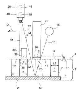
Figure 5 shows the general principle of an
inspection method according to the inventian and an
inspection instrument 160 according to the invention.
Elements identical to elements in the inspection
instrument according to prior art are marked with the
same numeric references.
Figure 5 shows a sectional view of a honeycomb 1
comprising a honeycomb core 3 formed from adjacent
cells 5 and separated by partitions 7. Said honeycomb
core 3 is bonded on one side to a skin 2 and on the
other side forms a free surface 4 containing the
openings 6 of the cells 5. A bond defect 50 is located
between two cells.
An inspection instrument 160 moves along a
direction D, with incremental or continuous scanning
above the free surface 4 of the honeycomb core 3.
CA 02465390 2004-04-28
SP 22814 VD 11
In the same way as the inspection. instrument
according to prior art, the inspection instrument in
figure 5 comprises:
- a first mask 26 with an illumination edge 27 and
an. observation edge 28 on which a screen 29 may
be fitted, said first mask 26 covering a first
intermediate area 25 located between an
illuminated area Z7 and an observed area 22,
- a light source 15 fixed to the first mask 26
that emits incident light 16 illuminating the
bottom of the cells 5,
- first detection means 20 capable of
automatically detecting light 21 emerging from
the bottom of the cells 5, said emerging light
21 being derived from incident light 16 that
passed through the bond defect 50.
The inspection instrument 160 also comprises:
- a second mask 36 on top of which there may be a
screen 39, said second mask 36 being fixed to
the first mask 26 and located in, front of it at
a distance M chosen such that emerging light
passes between the first mask 26 and the second
mask 36 when said two masks 26, 36 move
forwards,
- retaining means (not shown) to hold the first
mask 26 and the second mask 36 at a given height
H above the free surface 4, said height H
preferably being equal to at least 2
centimeters,
- second detection means 40 capable of
automatically detecting openings 6 of the cells
CA 02465390 2004-04-28
SP X2814 VD 12
in a so-called photographed area 32, said
photographed area 32 being located in front of
the observed area 22, and separated from it by a
second intermediate area 35.
5 The minimum distance between said observed area 22
and said photographed area 32, taken along the
direction D, is denoted F and is greater than the width
L1 of the openings 6.
The function of the second mask 36 is to act as an
obstacle to light that could arrive on the observed
area 22. The distance M between the ffirst mask 26 and
the second mask 36 is preferably greater than the width
L1 of a cell 5, so that light illuminating the
photographed area 32 does not arrive in a cell 5 that
is currently being observed.
In the example illustrated in figure 5, openings 6
are detected by second detection means 40 (arrow 31)
with ambient light. As a variant, it could be made by
illuminating said cells 5 using an additional light
source placed in front of the second mask 3& and fixed
to it.
In the example illustrated in figure 5, the first
automated detection means 20 and the second automated
detection means 40 are coincident. For example, they
may consist of a camera for continuous scanning of the
inspection instrument 160 above the free surface 4, or
a still camera for incremental scanning of said
inspection instrument 160.
Preferably, the signal processing means 46 and
image processing means 48 are associated with the
CA 02465390 2004-04-28
SP 2814 VD 13
detection means 20, 40. For example, a CCD type camera
will be used.
The signal processing means 46 transform signals
detected by the detection means 20, 40 into optical
images 60a, 60b in the form of matrices of pixels.
Figure 6A shows such an optical image 60a obtained
by processing of a signal originating from emerging
light 21. Spots 200 appear on this optical image 60a.
They may correspond to emerging light 21 representative
of a bond defect 50 (see figure 5). They may also
correspond to parasite reflections 18 originating from
reflection of incident light 16 on the top edges of
partitions 7, in a manner similar to what has been
described with reference to figure 3 for the variant of
the method according to prior art.
Figure 6B shows another optical image 60b obtained
by processing of a signal originating from the openings
6 of the cells 5. Contours 77 can be seen on this
photograph type image 60b. These contours correspond
to openings 6 of the cells 5 arLd delimit areas 5'
representative of the cells 5. The distance d between
two approximately parallel sections of contours 77
corresponds to the thickness of the partitions 7
separating the cells 5. Lines 7' are shown in dashed
lines, as a theoretical representation of the contours
of the cells 5.
The image processing means 48 use the image
processing steps of the inspection method. During
these steps, which are carried out using calculation
means not shown, the optical image boa containing spots
100 and the optical image 60b containing contours 77
CA 02465390 2004-04-28
SP 22814 VD 14
are superposed as shown diagrammatically in figure 6A.
The position of the spots 100 and. the position of the
contours 77 are then compared. Spots 100 that are at
least partially superposed with an area between two
approximately parallel sections of contours 77 are
identified as being spots corresponding to parasite
reflections 18. A third optical image 60c is then
created from which spots corresponding to parasite
reflections 18 have been removed, and on which all that
remains are spots 50' that are not at all superposed
with areas included between two approximately parallel
sections of contours 77, that are representations of
the partitions 7. These spots 50' are then identified
as being representative of bond defects 50. The
theoretical lines 7' are also shown in dashed lines on
the third optical image 60c, so that the figure is
easier to understand.
This type of image 60c makes :it easy to see which
cells are affected by a bond defect.
An additional image processing operation creates a
resultant optical image on which the presence of bond
defects 50 is displayed in a coded manner. Figure 7
illustrates an example of such a resultant optical
image 70. Cells affected by a bond defect are
represented in a first color (for example white) and
cells not affected by a bond defect are shown in
another color (for example grey or black).
An optional variant embodiment of the inspection
instrument is shown in figure 8. According to this
variant, the inspection instrument 160 is such that,
for N successive geometric points A on the illumination
CA 02465390 2004-04-28
SP 22814 VD 15
edge and N successive geometric points B on the
observation edge, where N is equal to at least five,
the distance AB between the illumination edge and the
observation edge is minimal and is equal to E, the
distance D1 between two geometric points A being equal
to at least 0.5 x E, the distance D2 between two
geometric paints B also being equal to at least 0.5 x
E, the N geometric points A forming an open line for
which the distance between the two geometric points A
formed at its ends is greater than the distance between
any other pair of geometric point~~ A, the N geometric
points B also forming an open line for which the
distance between the two geometric points B at its ends
is greater than the distance for any other pair of
geometric points B.
The invention is not limited to the embodiments
that have just been described.
Without going outside the scope of the invention,
it would be possible for the first detection means and
the second detection means to be separate and connected
to each other.
The cells shown in the figures are hexagonal
cells. But obviously, the method. according to the
invention and the inspection instrument according to
the invention are suitable for demonstrating bond
defects between a honeycomb core and a skin for non-
hexagonal cells, for example quadrangular or rounded
cells.
In the inspection configuration that has just been
described, the light source 15 is behind the first mask
26, the first and second detection means 20, 40 are in
CA 02465390 2004-04-28
SP 22814 VD 16
front of the first mask 26, and the second mask 36 is
in front of the first mask 26. It would be possible to
envisage an inverse configuration in which the light
source 15 would be in front of the first mask 26,, the
S first and second detection means 20, 40 would be behind
the first mask 26 and the second mask 36 would be
behind the first mask 26.
Note that the relative positions of the light
source for the first and second detection means and the
second detection mask with respect to the first mask,
are not related to the direction of displacement of the
inspection instrument. In other words, the instrument
may be moved along the direction D defined as being the
direction from the light source to the camera, as
indicated in the attached figures, but it could equally
well be moved in the opposite direction.
CA 02465390 2004-04-28