Note: Descriptions are shown in the official language in which they were submitted.
CA 02465572 2004-04-28
SUPPORT POLE AND RAIL SYSTEM
Field of the Invention
This invention relates to the field of support structures such posts, rails
and like
devices installed to assist the elderly and handicapped and in patient
handling, and in particular to
poles releasably mountable between a floor and ceiling so as to provide a
ready and stable
handgrip for the elderly, infirm or handicapped and to support structures
mountable to and
between such poles.
Background of the Invention
It is known in the prior art to provide rails or poles such as described in
Canadian
Patent No. 1,291,470 which issued to Lunau et al on October 29, 1991 for a
Safety Support
Structure, wherein a post having upper and lower ends adapted to abut firmly
against a ceiling and
floor surface respectively is provided. Further, as taught by Lunau, an
accessory mounting region
is disposed between the upper end and the lower end. Further, the post has a
length adjustment
means and a pressure indicating means to indicate whether the pressure on the
structure, when
positioned between the floor and the ceiling, lies inside or outside a
predetermined range of
2 0 pressures so as to avoid inflicting damage on the floor or ceiling surface
and so as to inhibit
slippage of the post. Rails or like laterally extending support accessories
are mountable onto the
post at the accessory mounting region by clamping thereto so as to resist
axial or rotational
displacement of the rail or like support accessories relative to the post. The
pressure indicating
means is a viewing eye to view a colour indicator on a sleeve slidingly
journalled behind the
2 5 viewing eye such that the sleeve slides past the viewing eye as a
compression spring is
compressed.
1
CA 02465572 2004-04-28
Applicant is also aware of Canadian Patent No. 2,096,681 which issued to
Mardero
et al. on June 4, 1996 for a Safety Rail Attachment. The Mardero et al. Safety
Rail Attachment
discloses a security rail attachment for a bed having a post with an
adjustable foot at a lower end, a
rail portion mounted within the post and rotatable about the vertical axis of
the post, and an
attachment rail which extends across the end of the bed which includes
clamping elements for
clamping to angle irons along the sides of the bed. The rail portion may
project outwardly from
the bed, perpendicularly thereto, for assisting a user in standing or may lie
along the side of a bed
as a rail bed.
Applicant is also aware of Canadian Patent Application No. 2,121,731 which was
filed April 20, 1994 and laid open October 24, I 994, for the Bathing
Apparatus for the Infirm of
Mardero et al. In his '731 application, Mardero teaches a modular system for
conventional tub and
shower enclosures where a pivotable support bar member may be positioned so as
to project
outwardly from a rear wall of the enclosure to assist the user standing in the
enclosure.
Applicant is also aware of Canadian Patent No. 2,148,521 which issued May 21,
2002 for a Support Pole with Pivoting and Locking Handrail for Elderly and
Disabled Persons.
What is disclosed is a telescopic pole adapted to be vertically fixed between
a floor and ceiling of
a room and having a horizontal handrail pivotally mounted thereon.
Applicant is also aware of United States Patent No. 6,575,100 which issued
June
10, 2003 to Faucher et al. for Support Structures, wherein a patient handling
system including a
telescopic track extending between a pair of telescopic masts is disclosed.
2 5 Summary of the Invention
'The safety support poles and poles-and-rail system according to the present
invention may include a pair of such poles supporting an elevated rail
extending therebetween.
2
CA 02465572 2004-04-28
Each pole has upper and lower ends adapted to abut firmly and releasably
against opposed ceiling
and floor surfaces respectively. Length adjustment means are mounted into the
end cooperating
with a releasably mountable torque application means, and in one embodiment
also torque
indicating means, releasably mountable onto, so as to cooperate with, the
length adjustment
means. Resilient biasing means mounted in the upper end resiliently bias the
upper end away from
pressure distributing means for distributing pressure onto the ceiling surface
along a longitudinal
axis of the support pole. The base mounting of the pole and the mounting of
the rigid rail between
the poles resists rotational movement of the upper end relative to the
pressure distributing means.
The lower end of the pole is non-rotatably mountable to a base member
releasably positionable on
the floor surface in vertically opposed relation to the pressure distributing
means. A torque may
thus be applied by the torque application means at the upper end.
Advantageously, the pressure distributing means includes an upwardly concave
resiliently bowed elongate pressure bearing member adapted to be mounted to
the upper end
medially along the length of the member and sufficiently long so that opposite
end portions of said
member bear upwardly against ceiling studs or joints or other rigid ceiling
supporting members
(collectively herein "studs").
Advantageously, the length adjustment means is an elongate threaded member
2 0 threadably mountable longitudinally within a cavity in the upper end of
the pole, although
mounting same within the lower end of the pole is intended within the ambit of
the present
invention. The threaded member is threadably mountable into threaded
engagement within a
threaded receiving means such as a threaded collar mounted on the upper end of
a helical spring
itself mounted on the upper end of the pole. The torque application means
cooperates with the
2 5 elongate threaded member so as to rotate in threaded engagement the
elongate threaded member
within the threaded receiving means when a torque is applied by the torque
application means and
to thereby extend the elongate threaded member from, or retract the elongate
threaded member
into, the upper end selectively according to opposite first or second
directions of rotation of the
3
CA 02465572 2004-04-28
elongate threaded member about the longitudinal axis. An upper end of the
threaded member
mates with, or mounts into or with, a non-rotatable coupler on the pressure
bearing member so as
to inhibit rotation of the threaded member relative to the pressure bearing
member about the
longitudinal axis of the pole.
Further advantageously, the torque application means is a torque rod or other
lever
or handle (collectively referred to herein as a torque rod) snugly releasably
mountable into a
corresponding socket mounted to the threaded collar so that the rod protrudes
cantilevered
generally perpendicularly from the threaded collar when the torque rod is
releasably mounted in
the socket, and wherein the upper end of the elongate threaded member extends
journalled through
the spring from the upper end of the pole when the elongate threaded member is
in threaded
engagement within the threaded collar.
In one aspect of the present invention, the means for resisting rotation of
the upper
end relative to the pressure distributing means is a means for rigidly non-
rotatably mounting the
lower end of the pole to the base member.
Yet further advantageously, the torque rod is adapted to be generally rigid
below a
first torque value and adapted to flexibly deform above the first torque
value. The first torque
2 0 value may correspond to a torque applied in the first or second rotational
direction to the elongate
threaded member so as to apply a corresponding first pressure against the
ceiling surface by the
pressure distributing means and against the floor surface by the base member,
wherein the first
pressure is sufficient to securely fractionally mount the pole vertically
between the ceiling and
floor surfaces without damaging either the ceiling surface or the floor
surface, and in a preferred
2 5 embodiment to also flatten the bowed pressure bearing members against the
ceiling and the floor
without damage to either the ceiling or floor.
4
CA 02465572 2004-04-28
In the prior art, poles may be made of smooth steel with an added foam grip,
molded plastic handgrip ribs over the smooth steel poles or textured grit in
or on top of surface
paint. The support pole according to the present invention may have hand grip
grooves greater
than one eighth inch in depth which are crimped into the steel wall of the
pole and which may be
manufactured more efficiently than in the prior art while still providing a
safe and durable hand
grip surface.
Prior art poles have an outer cover which slides up the outside of the pole to
hide
the adjustment threaded rod and which is not firmly attached to the pole
during storage or
transport. During cleaning, water or cleaning solutions may run down the pole
and into the inside
of this cover which then funnels it down the inside of the cover and then onto
the floor plate. The
fluid inside the outer cover cannot be removed and so may continue to weep out
onto the floor
plate and nearby flooring for a period of time after the cleaning, which in
turn can lead to a
slipping accident. The present pole has the outer cover inside the pole tube
so as to keep any water
or cleaning fluids flowing down the outside of the pole and outer cover. This
design allows all of
the cleaning fluid to be removed from the pole and floor plate thereby
preventing a possible
slipping accident. The outer cover remains attached to the pole so as not to
become lost during
transport or storage.
2 0 In the prior art, poles are mounted to ceiling channels which are less
than twenty-
four inches in length and which must be positioned directly under and at right
angles to the ceiling
support structure, the studs, to prevent damage to the ceiling. The pole of
the present invention
uses a channel which is greater than twenty-four inches in length so that when
oriented on the
diagonal across the ceiling, the longer span of the channel will result in the
center of the channel
2 5 (the pole attachment point and center of pressure) always being either
under a ceiling support or
will span between two adjoining ceiling support structures thereby preventing
possible ceiling
damage. This also eliminates the need and safety hazard in using a ladder and
stud finder to locate
the ceiling support structures above the ceiling and determine the orientation
of these ceiling
5
CA 02465572 2004-04-28
support structures. The design of having a ceiling channel with a longer
length than that of any
cantilevered accessory, such as a cantilevered arm, being mounted on the same
pole results in a
higher torque resistance for the ceiling channel than the torque generated by
the accessory. This
reduces the chance that the ceiling channel will slip when subjected to strong
torque from a person
using an accessory.
Prior art poles use floor plates and ceiling channels which are flat, that is
un-bowed.
The pole of the present invention mates to a pre-arched (bowed) floor plate
and ceiling channel,
which as it flattens against the floor/ceiling more evenly distributes the
pressure on the
floor/ceiling to prevent damage to the flooring or ceiling. Creating more
pressure and thereby
more grip on the outer ends of the channel and floor plates makes them less
likely to slip on the
floor or ceiling when subjected to twisting forces. Holding the pole more
firmly in place reduces
the likelihood that the pole will come free and fall down when subjected to a
severe pull or
twisting action by a user pulling on the pole or cantilevered accessory.
Prior art poles typically use set screws to attach their accessories. Such set
screws
may dig into or through the paint finish and then dent the steel pole in order
to hold the accessory
firmly in place. The pole of the present invention attaches all accessories
using a protective sleeve
which prevents damage to the paint finish. The attachment mechanism includes a
clamping band
2 0 which evenly distributes pressure over the plastic sleeve and underlying
pole to inhibit distortion
or denting of the pole. This allows the accessories to be securely attached
anywhere along the
length of the pole without incurring any damage to the pole. This design also
incorporates a
limited slip action between the protective sleeve and the surface of the pole.
This safety feature
limits the twisting torque exerted on the ceiling channel by an attached
accessory and thereby
2 5 prevents the ceiling channel from slipping on the ceiling, which might in
turn cause the pole to fall
down.
6
CA 02465572 2004-04-28
Prior art poles may have an accessory comprised of a single handrail bar or
pivoted
handle. The pole of the present invention may include an accessory such as a
long handrail loop.
This design provides a horizontal and vertical surface out from the pole,
which offers more hand
hold positions. The large radius foam covered end of the loop is less likely
to inflict serious
injuries and bruises caused by a fall against the end of the handrail. The
loop design affords
greater weight bearing without damage or structural failure. Unlike prior art
which can be
positioned to resist torsional rotation forces which has resulted in a
rotational separation at either
the floor or ceiling and a lateral shifting of the pole, this device uses a
positioning collar which is
cinched tightly aver a plastic sleeve. The collar permits rapid positioning of
the handle along the
length of the pole while the handle is free to rotate about the collar.
Prior art poles may also have an accessory comprised of a trapeze handle
suspended
from a single support bar. The pole of the present invention may include a
support bar having an
attached diagonal suspension rod that provides additional strength, which in
turn allows the
support bar to be longer while still maintaining the same suspended weight.
The longer reach of
the support bar places a trapeze handle further out over the bed or chair
where it is usually required
by a patient.
Prior art poles may further have an accessory tray comprised of a simple hook-
on
2 0 attachment. The pole of the present invention may have a tray which
includes a strong steel frame
and bushing which allows the tray to be repeatedly moved back and forth or
rotated around the
pole without denting the pole or damaging the finish on the pole. The clamping
design of the
bushing allows the tray to remain at the desired height even when rotated back
and forth or around
the safety pole.
Safety poles of the present invention, when used in pairs or in tandem, with a
connector rigidly mounted near the upper end, may support between them a rigid
rail or track.
7
CA 02465572 2004-04-28
This track is configured to accommodate a conventional patient hoist and
associated harness well
known in the art.
In summary, the vertical support pole of the present invention includes
opposite
upper and lower ends adapted to abut firmly and releasably against opposed
ceiling and floor
surfaces respectively. Length adjustment means are mounted into the pole so as
to cooperate with
a releasably mountable torque application means releasably mountable onto, so
as to cooperate
with, the length adjustment means. A resilient biasing means is mounted in the
pole resiliently
biasing the opposite ends of the pole apart along a longitudinal axis of the
pole. A pressure
distributing means is mounted onto the upper end of the pole. The pressure
distributing means is
for distributing pressure onto the ceiling surface. The upper end is adapted,
by releasable
mounting means cooperating with the pressure distributing means, to resist
rotational movement of
the upper end relative to the pressure distributing means. The lower end is
mountable to a base
member on the floor surface. The base member is in vertically opposed relation
to the pressure
distributing means. The pole may further include a bushing mounted to the pole
positioned along
the length of the pole. An accessory mounting sleeve is mounted onto the
bushing for mounting
thereto of accessories for the pole. As the length of the pole is increased by
the length adjusting
means, the resilient biasing means increases a biasing force urging the ends
of the pole apart.
2 0 In one embodiment, the base member may be curved concavely downwardly. It
may be resilient so as to resiliently deform under the pressure exerted along
the longitudinal axis
of the pole by the resilient biasing means to thereby flatten against the
floor surface, and to re-form
into the concavity upon any compacting down of the floor surface.
The resilient biasing means may be a coil spring. The length adjustment means
may be an elongate threaded member threadably mountable longitudinally within
a cavity in the
pole, wherein it is threadably mountable into threaded engagement within a
threaded receiving
means mounted on the spring. The upper end of the elongate threaded member
extends j ournalled
8
CA 02465572 2004-04-28
through the spring from the upper end of the pole when the elongate threaded
member is in
threaded engagement within the threaded collar. An upper end of the threaded
member mates with
a non-rotatable coupler on the pressure bearing member so as to inhibit
rotation of the threaded
member relative to the pressure bearing member about the longitudinal axis of
the pole.
The torque application means cooperates with the elongate threaded member so
as
to rotate in threaded engagement the elongate threaded member within the
threaded receiving
means, which may be a threaded collar, when a torque is applied by the torque
application means.
'The elongate threaded member is thereby extended selectively from, or
retracted into, the upper
end according to opposite first or second directions of rotation of the
elongate threaded member
about the longitudinal axis of the pole. The torque application means may be a
torque rod snugly
releasably mountable into a corresponding socket mounted to or in the threaded
collar so that the
rod protrudes cantilevered generally perpendicularly from the threaded collar
when the torque rod
is releasably mounted in the socket.
The torque rod may be adapted to be generally rigid below a first torque value
and
adapted to flexibly deform above the first torque value. The first torque
value corresponds to a
torque applied in the first or second rotational direction to the elongate
threaded member so as to
apply a corresponding first pressure against the ceiling surface by the
pressure distributing means
2 0 and against the floor surface by the base member, wherein the first
pressure securely frictionally
mounts the pole vertically between the ceiling and floor surfaces without
damaging either the
ceiling surface or the floor surface.
The upper end may advantageously be mounted to the pressure distributing means
2 5 by a universal joint means. The pressure distributing means may include an
upwardly concave
resiliently bowed elongate pressure bearing member adapted to mount to the
upper end generally
medially along the length of the member and elongate a sufficient length so
that opposite end
portions of the pressure bearing member may be brought to bear upwardly
against ceiling studs
9
CA 02465572 2004-04-28
supporting the ceiling surface. The pressure bearing member may be deformable
under the
pressure exerted along the longitudinal axis by the resilient biasing means.
The first torque value
may also be sufficient to flatten the bowed pressure bearing member.
In one preferred embodiment of the present invention the bushing is a split
bushing,
and may be resilient. The mounting sleeve may be a split sleeve having
clamping means mounted
thereon for releasably clamping the sleeve onto the bushing.
The accessories for mounting on the pole of the present invention may include
a
rigid loop which, when mounted to the pole, is cantilevered outwardly of the
pole by the length of
the loop, the loop being elongate along its length. The accessories may also
include a rigid rail
connector for the mounting of a rigid rail extending between a pair of the
poles.
In one embodiment, the lower end of the pole is mounted onto the base member
by
means of a male member in mating engagement with a female receiver. The male
member may
have at (east one ridge along its length for snug frictional mating with the
female receiver. The
male member may be mounted to the base member. The female receiver may be a
cavity in the
lower end of the pole. Crimped handgrip grooves may be formed on an outer
cylindrical surface
of the pole.
A pressure-level indicating means may cooperate between the coil spring and
the
threaded member so that, as the spring is compressed with the rotation of the
threaded member in
threaded engagement with the threaded receiving means, a pressure indicating
marker signals
excessive force at a damage threshold for the ceiling or floor. The marker may
be a contrasting
2 5 band on a tube extending along the spring.
CA 02465572 2004-04-28
Brief Description of the Drawings
Figure 1 is, in perspective view, a prior art pole mounted between a ceiling
and
floor.
Figure 2 is, in side elevational view one form of support pole of the present
invention.
Figure 2a is in perspective view, a portion of Figure 2.
Figure 2b is a sectional view taken on line 2b-2b of Figure 2a.
Figure 3 is an enlarged, partially exploded perspective view of an alternative
form
of support pole.
Figure 3a is an enlarged view of a portion of Figure 3.
Figure 4 is a sectional view along line 4-4 in Figure 3.
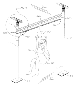
Figure 5 is, in perspective view an alternative support pole.
Figure 6 is, in perspective view, a pair of poles supporting a rail mounted
therebetween according to one preferred embodiment of the present invention.
Figure 7 is an enlarged, partially exploded, portion of Figure 6.
Figure 8 is a sectional view along line 8-8 in Figure 7.
11
CA 02465572 2004-04-28
Figure 9 illustrates in elevation view, an accessory bax mountable to the
support
pole of the present invention.
Figure 9a is an enlarged perspective view of a portion of Figure 9.
Figure 10 is in elevational view, a grab rail mountable to the support pole of
the
present invention.
Figure l0a is in enlarged perspective view a portion of Figure 10.
Figure 11 is in elevational view a swing-arm table mountable to the support
pole of
the present invention.
Figure 11 a is a sectional view taken on line 11 a-11 a of Figure 11.
Figure 12 is, in partially cut-away perspective view a portion of the swing
arm table
of Figure 11.
Detailed Description of Embodiments of the Invention
As seen in Figure l, it is known in the prior art to provide poles having an
adjustable length and which are mountable between ceiling and floor surfaces
where a pressure
indicating means is provided along the length of the pole such as described
above in relation to
Canadian Patent No. 1,291,470 from which the illustration of Figure 1 is
taken. Within that
2 5 illustration an adjustment means is generally indicated by reference
numeral 2. Adjustment means
2 incorporates an adjustment nut (not shown) which may be longitudinally
translated along a
threaded piston by rotation of the outwardly disposed collar 4. Translation of
the adjustment nut
compresses a spring (not shown) as the adjustment nut is translated along a
viewing slot or
12
CA 02465572 2004-04-28
window 6. The amount by which the adjustment nut is translated relative to the
viewing slot or
window against the return biasing force of the spring indicates the pressure
exerted longitudinally
along the length of the pole and against the ceiling and floor support
surfaces. It is one of the
objects of the present invention is to provide a simplified mechanism for
indicating proper
pressure adjustment when installing a safety pole and maintaining the pressure
exerted by a safety
pole to account for compaction of a carpet or underlay on the floor surface or
movement of ceiling
joists.
As seen in Figures 2-12, wherein similar characters of reference denote
corresponding parts in each view, one embodiment of the safety support pole 10
according to the
present invention has an upper end 12 and a lower end 14 and a mid-section 16
therebetween.
Safety support pole 10 may be hollow along its entire length or merely hollow
at its upper and
lower ends.
As seen in the embodiment of Figure 2, a length adjusting device 17 is mounted
into the hollow end of lower end 14. The length adjusting device includes an
elongate threaded
member 18 threadably mounted into threaded cooperating engagement within
threaded nut or
collar 20. Threaded nut or collar 20 may be rigidly mounted within lower end
14 or may be a snug
fitment so Iong as threaded nut or collar 20 is held rigid relative to lower
end 14 when elongate
2 0 threaded member 18 is rotated about a longitudinal axis A of pole 10 by
rotation of elongate
threaded member 18 in direction B. Elongate threaded member 18 is rotated
about longitudinal
axis A in direction B by means of a rotational torque applied by torque rod 22
when releasably
mounted into bore hole 24 along axis C.
2 5 The lowermost end of elongate threaded member 18 may be rigidly mounted
into a
safety cover or sleeve 26, in which case, aperture 29 is provided in sleeve 26
so as to journal
torque rod 22 therethrough when releasably mounting torque rod 22 into bore
hole 24.
13
CA 02465572 2004-04-28
Bore hole 24 is oriented so that torque rod 22 extends generally
perpendicularly or
is otherwise cantilevered from elongate threaded member 18 and sleeve 26 when
torque rod 22 is
journalled within bore hole 24.
Torque rod 22 is conveniently mountable into elongate threaded member 18 at
lower end 14 so that a user may merely bend down, insert torque rod 22 into
bore hole 24 and
mtate elongate threaded member 18 and sleeve 26 by using torque rod 22 as a
lever so as to adjust
the length of pole 10 and the pressure exerted by upper end 12 and lower end
14 against floor 28
and ceiling 30 respectively. Torque rod 22, which may be steel or bronze or
like malleable or
ductile material or otherwise as in the manner of torque wrenches known in the
art, is calibrated so
that a desired torque may be applied when rotating shaft 18 as top and bottom
bearing plates
flatten out so that a calibrated known pressure is then applied to ceiling 30
and floor 28 along axis
A so as to prevent damage to the ceiling and floor.
Barrel 32 may be rigidly mounted to threaded nut or collar 20 and is rigidly
mounted within lower end 14 by means of spacer 36 welded into place by means
of plug or spot
welds 36a. The purpose of barrel 32 is to assist in longitudinally stabilizing
elongate threaded
member 18 along longitudinal axis A. Thus, barrel is sized so as to snugly fit
over elongate
member 18 at an end of barrel 32 distal from threaded nut or collar 20 so as
to snugly stabilize
2 0 elongate threaded member 18 therein.
The lowermost end of elongate threaded member 18 or of sleeve 26 may extend as
a nipple 40. Nipple 40 may be encased in a friction reducing collar 42 which
may be of Teflon,
plastic or other friction reducing material sized to be snugly inserted into
corresponding aperture
2 5 44 in base plate 46. Base plate 46 may have resilient or otherwise
cushioned pad 48 mounted to an
underside thereof so as not to mark or damage floor 28. Thrust washer 50 may
provide a bearing
surface between a lowermost end of elongate member 18 or sleeve 26 and the
upper surface of
base plate 46.
14
CA 02465572 2004-04-28
Upper end 12 has collar 52 rigidly mounted therein as by bolt 54 or other
method of
rigidly securing collar 52 within upper end 12. Helical spring 56 may be
mounted to, or bear
against, collar 52 at the lowermost end of the spring, and may be mounted to
or bear against
bearing disc 58 at its uppermost end.
Bearing plate 60, which may be an elongate channel member 60a or a plate 60b
(as
may be seen in Figure 1 ) or like means for distributing pressure against
ceiling 30 cooperates with
pole 10 by splines 62a and 62b rigidly extending between bearing plate 60 and
bearing disc 58.
Crimped handgrip grooves 161 may be provided along the outer surface of the
pole.
As may be seen in Figures 2,3 and 3a , splines 62a and 62b may be a generally
parallel spaced apart pair of planar flanges rigidly mounted to a base 64,
spaced apart so as to
receive therein in sliding engagement along longitudinal axis A, a laterally
extending rigid member
such as bolt 66. Bolt 66 slides between splines 62a and 62b as relative
movement between upper
end 12 and bearing plate 60 causes splines 62a and 62b to compress helical
spring56. The spacing
between splines 62a and 62b is such that, although bolt 66 is free to slide
along longitudinal axis A
it may not rotate a significant distance in a radial arc about longitudinal
axis A, being constrained
between splines 62a and 62b. The combined effect at the upper end of the pole
is that of a
2 0 universal joint which provides for flexing of the pole, during use for
example, without tilting of
the bearing surfaces bearing against the ceiling. The channel thus remains
flush against the
ceiling, in full frictional engagement thereagainst. In the embodiment of
Figures 4-5, nut 34 is free
to tilt within splines 62a and 62b, which act as an end cap over nut 34.
2 5 Thus, because bolt 66 is mounted rigidly to upper end 12, pole 10 is not
free to
rotate about longitudinal axis A when a torque is applied by torque rod 22 so
as to rotate elongate
threaded member 18 in direction A. Thus relative rotational movement is
achieved between
elongate threaded member 18 and threaded nut or collar 20 so that, depending
on whether elongate
CA 02465572 2004-04-28
threaded member 18 and threaded nut or collar 20 are left or right hand
threaded and depending on
the direction of rotation on elongate threaded member 18 relative to threaded
nut or collar 20,
elongate threaded member 18 is either extended from or retracted into lower
end 14.
Extending elongate threaded member 18 from lower end 14 so as to bear against
base plate 46 positioned on floor 28, translates upper end 12 along
longitudinal axis A towards
ceiling 30. The upwards force is transferred through bolt 54 so as to compress
helical spring 56
against bearing disc 58as splines 62a and 62b are engaged against bearing
plate 64.
Once initially snugged against ceiling 30, bearing plate 60 provides
sufficient
friction between ceiling 30 and bearing plate 60 so as to resist relative
movement therebetween.
Thus, rotation of torque rod 22 does not have to be countered by hand applied
torque to pole 10
once bearing plate 60 has been mugged against ceiling 30 and nipple 40 snugly
inserted into
aperture 44 so that sleeve 26 bears against thrust washer 50.
Alternatively, in the embodiment of Figures 4, 4a, 4b and 5-8, nipple 40 may
be
alternatively formed as an upstanding ring 40' secured to the upper surface of
base plate 46.
Raised ridges 40a' on the outer surface of ring 40' allows end 14 of pole 10
when firmly seated
over ring 40' to resist torsional forces while allowing some flexure of the
pole.
Length adjusting device 17 may in the embodiment of Figures 4-8 be mounted on
or into the upper end 12. In the embodiment of Figure 7, the length adjusting
device includes an
elongate threaded shaft or member 18 threadably mounted into threaded
cooperating engagement
within threaded nut or collar 24. Threaded nut or collar 24 may be rigidly
mounted within upper
2 5 end 12 or may be a snug fitment so long as threaded nut or collar 24 is
held rigid relative to upper
end 12 when elongate threaded member 18 is rotated about a longitudinal axis A
of pole 10 by
rotation of nut 24 in direction B. A threaded coupler such as hexagonal nut
24a is rigidly mounted
to nut 24. Nut 24 is rotated about longitudinal axis A in direction B by means
of a rotational
16
CA 02465572 2004-04-28
torque applied by torque rod or handle (collectively a rod) 22 when releasably
mounted into the
threaded bore of nut 24a along axis C. Nut 24a is oriented so that torque rod
22 extends generally
perpendicularly from elongate threaded member 18 when torque rod 22 is
journalled within nut
24a. Torque rod 22 allows a user to rotate elongate threaded member 18 and
sleeve 26 by using
torque rod 22 to adjust the length of pole 10 and thereby adjust the pressure
exerted by upper end
12 and lower end 14 against ceiling 30 and floor 28 respectively, Threaded
member 18 may be
painted or otherwise adapted with colored bands so that, for example, a red
band 32c becomes
visible when threaded member 18 has extended to a point where damage or injury
could result, or
a
more simply indicates that an extension tube is required. Should the safety
pole be installed upon
a carpeted floor and compaction of the carpet and underlay occur over time,
the spring will push
the pole down into the carpet and underlay and the red band will become
visible indicating that
threaded member 18 must be lengthened until the red band is no longer visible.
Collar 32a may be rigidly mounted to threaded nut or collar 24. Collar 32b is
a
snug sliding fit within upper end 12. The purpose of both collars 32a and 32b
is to assist in
longitudinally stabilizing elongate threaded member 18 along longitudinal axis
A. Collar 32b is
mounted on member 18 and also provides for visual pressure indication by the
presence of red
band 32c thereon.
2 0 Bearing plate 60, which may be an elongate channel member or an oval plate
(not
shown) or like means for distributing pressure against ceiling 30 cooperates
with pole 10 by
flanges 62a and 62b, which are rigidly mounted in the channel to form a
locking cap, releasably
mounting onto hexagonal-head nut 34 so as to prevent its rotation.
2 5 Thus, because threaded shaft 18 is rigidly mounted at its upper end to nut
34, shaft
18 is not free to rotate about longitudinal axis A when a torque is applied by
torque rod 22 so as to
rotate threaded shaft 18 in direction B. Thus relative rotational movement is
achieved between
shaft 18 and collar 20 so that, depending on whether shaft 18 and collar 20
are left or right hand
17
CA 02465572 2004-04-28
threaded and depending on the direction of rotation on shaft 18 relative to
collar 20, shaft 18 is
either extended from or retracted into upper end 12 of pole 10. Extending
shaft 18 from upper end
12 so as to bear against bearing plate 60 sandwiched against ceiling 30,
translates bearing disc 58
downwardly along longitudinal axis A away from ceiling 30 so as to compress
helical spring 56
between collars 32a and 32b. The return biasing force of helical spring 56 and
the weight of pole
bear lower end 14 down onto foot 36. Foot 46 is releasably mounted to lower
end 14 for
example by hollow ring 40 on the base plate of foot 46 which may have raised
ridges mating into
the hollow end of the tube at lower end 14. Base plate of foot 46 may be bowed
so as to be
concave downwardly to equalize, distribute and maintain the downward pressure
to the floor 28.
Once initially mugged against ceiling 30, bearing plate 60 provides sufficient
friction between ceiling 30 and bearing plate 60 so as to resist relative
movement therebetween.
Thus, rotation of torque rod 22 does not have to be countered by hand applied
torque to pole 10
once bearing plate 60 has been mugged against ceiling 30 and nut 34 snugly
mated between
flanges 62a and 62b. Advantageously, in one embodiment bearing plate 60 is
both sufficiently
long so that it will extend under ceiling studs 61 even if not aligned
perpendicular to the studs, and
is bowed so as to be concave upwardly (shown exaggerated by arrow D) to
equalize, distribute and
maintain the upward pressure to the studs 61 when the pole pushes up between
the studs.
2 0 As seen in Figures 6 through 8, connector 84 may be rigidly mounted near
the
upper end 12 of pole 10. Connector 84 provides, when used in pairs or tandem
on a corresponding
pair of poles, that the poles may support therebetween a rigid rail or track
86. Track 86 is
configured to accommodate a conventional patient hoist 90 well known in the
art. Hoist 90 has an
associated harness or sling 92 or the like, which supports patient 94 and
provides for patient
2 5 mobility through translation of hoist 90 along slot 88 defined by the
channel of track 86.
Connector 84 includes a lower supporting channel bracket 102. Bracket 102 may
be fastened to the pole for example by its welding onto a sleeve which is
mounted over top end of
18
CA 02465572 2004-04-28
pole or other fastening means. The sleeve may have an interior non-working
protection sleeve.
Connector 84 is cantilevered perpendicular to axis A. A vertical gusset 104
reinforces supporting
bracket 102.
Track 86 is a generally inverted U-shaped channel having a solid top web 112
and
downwardly depending sidewalls 114. Inturned flanges 114a are spaced apart by
slot 88 at the
distal ends of sidewalls 114 so that hoist 90 may be firmly supported on the
flanges and yet be free
to longitudinally travel the length of slot 88. Aperture 118 formed in top web
112 near each end
86a is aligned with corresponding hole 108 in bracket 102 as end 86a is seated
on bracket 102.
Threaded bolt 120 is passed vertically through hole 108 and aperture 118 in
top web 112 to
releasably mount end 86a to pole 10.
As illustrated in Figures 9 and 9a, cantilevered arm 130 is positioned at a
convenient height on pole 10 by means of vertical mounting sleeve 132. A
flexible strap and
trapeze handle 134 may be attached at a distal end. Rigid gusset 136 connected
at one end to
sleeve 132 and to arm 130 at its other end to resist vertically downward
bending torque when in
use by a patient. Sleeve 132 is split near its lower end 132a to permit
cinching in a desired
position on pole 10 by bolts 138. An elongate split bushing 140 manufactured
from P.V.C. or
other suitable plastic or resilient or otherwise gripping/protective material
is positioned between
2 0 pole 10 and mounting sleeve 132. Split bushing 140 allows arm 130 to be
cinched firmly to pole
10 by tightening of sleeve 132 onto the bushing so as to prevent either
marring of the exterior
finish of pole 10 as in the use of marring screws in the prior art, or
downward slippage of arm 10
during use while allowing some rotational repositioning of arm 130 around the
pole 10 by a
patient. It acts as a non-marking limited-slip clamp for any mounted
cantilevered attachments
2 5 such as arm 130.
As may be seen in Figures 10 and 10a, pole midsection 16 may have mounted
thereto support collar 68 so as to releasably support thereon hand rail 70.
Hand rail 70 is rigidly
19
CA 02465572 2004-04-28
mounted to sleeve 72 so as to depend generally perpendicularly from pole 10
and in particular so
as to extend generally perpendicularly from pole midsection 16 when mounted
thereon. Handrail
70 may be formed as a large radius loop for safety and strength. As stated
above, the long handrail
loop according to the present invention offers more handhold positions and the
large radius foam
covered end of the loop is less likely to inflict serious injuries and bruises
caused by a fall against
the end of the handrail. The loop design affords greater weight bearing
without damage or
structural failure. Unlike prior art which can be positioned to resist
torsional rotation forces which
has resulted in a rotational separation at either the floor or ceiling and a
lateral shifting of the pole,
this device uses a positioning collar which is cinched tightly over a plastic
sleeve. The collar
permits rapid positioning of the handle along the length of the pole while the
handle is free to
rotate about the collar. Sleeve 72 has upper and lower rings 74 and 74a, which
prohibit vertical
displacement of handrail 70 relative to mounting collar 68. Thus hand rail 70
with upper ring 74
secured in place by screws or the like to sleeve 72 may be lowered over collar
68 and then lower
toiler 74a fastened in a like manner to sleeve 72. . Hand rail ?0 may then be
rotated to different
and more convenient positions. Support collar 68 may be releasably mounted
onto pole
midsection 16 by means of clamping bolts 78 or other clamping means known in
the art.
Figures 11 through 12 illustrate the mounting of an accessory tray 150 to pole
10.
Tray 150 includes a steel frame 152 and a removable tray top 152a which is
rigidly mounted to
2 0 sleeve 154, by welding or the like, so as to depend generally
perpendicularly from pole 10. A
bushing 156 and clamping collar 158 are releasably cinched at the desired
position on pole 10 by
means of bolts 160 on collar 158. Sleeve 154 slips downwardly over bushing 156
and is supported
at the desired height on pole 10 by resting on collar 158. Bushing 156 allows
tightening of collar
158 and the rotation of tray 1 SO on pole 10 without marring the finish on
pole 10.
As will be apparent to those skilled in the art in the light of the foregoing
disclosure, many alterations and modifications are possible in the practice of
this invention
CA 02465572 2004-04-28
without departing from the spirit or scope thereof. Accordingly, the scope of
the invention is to be
construed in accordance with the substance defined by the following claims.
21