Note: Descriptions are shown in the official language in which they were submitted.
CA 02465581 2012-03-07
IN-WALL SPEAKER SYSTEM METHOD AND
APPARATUS
BACKGROUND OF THE INVENTION
Wall speaker systems have been used in various installation
assemblies in order to discretely produce music. Many systems are adapted
to take advantage of the column of air between the studs and the commonly
used dry wall layers. In modem day housing where living space is confined,
there is a tremendous benefit with the inherent space saving aspects of in-
wall speakers. Speakers themselves generally provide varying degrees of
aesthetic value. Generally because the focus of speakers is to produce high
quality sound, the speaker casing design effort is generally directed towards -
the acoustic properties of speaker assemblies and not the aesthetic aspects.
Therefore, aesthetics and removal from view is a further demand for in-wall
speakers. The in-wall speakers must still accomplish their utilitarian
function
of producing quality sound when they are not readily visible. By removing the
speaker assemblies from immediate view, the listener can direct their vision
toward objects that are designed for aesthetic appeal and still enjoy music or
other sounds produced by the speaker assembly.
=
CA 02465581 2004-04-29
2
SUMMARY OF THE INVENTION
As disclosed below, the disclosure shows embodiments for an in-wall
speaker system adapted to be concealed in a room and mounted to support
members. The in-wall speaker system comprises a base frame having an
open area. There is a speaker assembly mounted to the base frame and the
speaker assembly has a speaker frame and a reciprocating portion attached
to the speaker frame. The reciprocating portion has a driver and a cone
portion mounted to the speaker frame that is adapted to move in response to
an audio input signal.
There is also an active member having a peripheral region connected
to the base frame where the active member has an outward surface and an
inward surface. The inward surface, the base frame and the speaker
assembly define an acoustic chamber, whereby acoustic energy is transferred
from reciprocating member of the speaker to the active member so that the
outward surface transmits the acoustic energy as sound to the room.
CA 02465581 2004-04-29
3
BRIEF DESCRIPTION OF THE DRAWINGS
Fig. 1 shows an environmental view where the in-wall speaker system
is shown as a hatched line hidden from view from a listener;
Fig. 2 is a partial cross sectional view taken at line 2 -- 2 in Fig. 1 of the
speaker assembly;
Fig. 2A is a full cross sectional view taken at line 2 2 in Fig. 1 of the
speaker assembly;
Fig. 3 shows a partial cross sectional view of the high-frequency region
where high-frequency elements are connected to the reciprocating area on
the active member of the high-frequency region;
Fig. 4 shows a side partial cross sectional view of the in-wall speaker
system;
Fig. 5 shows the exploded view of an embodiment of the in-wall
speaker system;
Fig. 6 shows another embodiment of a portion in-wall speaker system
where the high-frequency elements are attached to a frame member or
bracket that has portions which are attached to high-frequency non-
reciprocating regions of the in-wall speaker system;
Fig. 7 shows a front view of another embodiment of the in-wall speaker
system where two speaker assemblies are employed;
Fig, 8 is a partial top cross sectional view of the embodiment of the in-
wall speaker system taken at line 8 ¨ 8 of Fig. 7;
Fig. 9 is a schematic view of a circuit that can be employed in the in-
wall speaker system;
Fig. 10 is a logarithmic graph showing one possible frequency
response of the speaker assembly and a cross-over region;
Fig. 11 shows a top partial cross sectional view of another embodiment
of the in-wall speaker system;
Fig. 12 is a front view of another embodiment of the in-wall speaker
system.
CA 02465581 2004-04-29
4
DETAILED DESCRIPTION
OF THE PREFERRED EMBODIMENTS
There will first be a general discussion of the environment where the in-
wall speaker system 20 can operate, followed by a detailed discussion of the
various embodiments of the in-wall speaker system 20. It is understood that
the various embodiments disclose, in a general way, the underlying concept
of the invention with the understanding that the invention is defined by the
claims herein below.
As shown in Fig. 1, the in-wall speaker system 20 is mounted behind a
wall section 10 that is a portion of a room generally indicated at 12. In one
operation, a listener 14 will hear the acoustic output of the in-wall speaker
system 20 without visually observing the source of the sound produced
therefrom. The wall section 10 comprises a surrounding wall section
generally indicated at 16. The surrounding wall section 16 indicates the
general perimeter area around the in-wall speaker system 20. After a detailed
discussion of the in-wall speaker system there will be a discussion of the
installation and various installation options. To aid the general description,
as
shown in Fig.1, an axes system 11 is generally defined where the arrow
indicated at 13 indicates a longitudinal axis. The arrow 15 generally
indicates
a lateral axis/direction and finally the arrow indicated at 17 indicates a
vertical
axis. The axes generally denote general directions and are no way intended
to limit the invention to any specific orientation but rather aid in the
description
of the components discussed herein.
Now referring ahead to Fig. 5, the in-wall speaker system 20 comprises
of a base frame 22, a speaker assembly 24 and an active member 26.
Further, a high-frequency system 28 is employed that is adapted to
better produce higher frequency sounds. Fig. 5 shows one method of
installing the high-frequency elements 102. Fig. 6 shows a second method of
installing the high-frequency elements 102 to the high-frequency region 58
discussed further below.
=
_
CA 02465581 2004-04-29
5
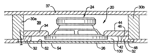
Referring back to Fig. 2, the in-wall speaker system is shown installed
between support members 30a and 30b. The support members generally are
wall studs made of wood or metal and spaced at or about 16 inches laterally
from one-another. In one form, the in-wall speaker system 20 can be
retrofitted to an existing wall installation, and in one form dry wall is set
up
where dry wall is positioned on top of vertical support members such as 30a
and 30b. In a retrofit situation, a portion of the dry wall is removed and the
in-
wall speaker system 20 is positioned in the location of the removed dry wall.
Thereafter, traditional dry wall techniques, such as spackling, can be applied
to the perimeter region to smooth the transition from the surrounding wall
section 16 (see Fig. 1) and the active member 26. The in-wall speaker
system 20 can also be installed during a dry wall set up where the installers
provide for an open region that corresponds to the approximate size of the in-
wall speaker system 20. Thereafter, spackling or the like is applied to the
perimeter region to smooth the transition between the surrounding wall
section and the active member. The active member is adapted to have paint
applied thereto to make the active member out of sight from people listening
to music 14.
There will now be a discussion of the components of the in-wall
speaker system 20. It should be understood that the various components are
one method of employing the invention where the invention resides in the
claims. The base frame 22 in one form comprises a perimeter frame 32 and a
rear baffle 34. The rear baffle 34 has a perimeter region 36 and a central
region 38. In one form, located in the lower central region, there is a
surface
defining an open area 40 having a perimeter region that is adapted to mount
the speaker assembly 24 thereto. The rear baffle 34 has a forward surface 42
and a rearward surface 44. The perimeter frame 32 has a rearward perimeter
surface 46 that is adapted to mount to the forward surface 42 of the rear
baffle
34. The perimeter frame 32 further has a forward perimeter surface 48 that is
adapted to mount to the perimeter region of the active member 26 described
further below. As shown in the lower portion of Fig. 4, the perimeter frame 32
CA 02465581 2012-03-07
6
has a longitudinal thickness 50 that is such to define a proper spacing
between the forward surface 42 of the rear baffle 34 and the inner surface 52
of the active member 26. The significance of the spacing is described further
below.
There will now be a discussion of the active member 26 followed by a
discussion of the speaker assembly 24 and the high-frequency system 28. As
shown in Fig. 5, the active member 26 has a rearward surface 52 (otherwise
referred to an inward surface 52) and a forward surface 54 (otherwise referred
to as the outer surface 54). As shown in Fig. 5, the rearward surface 52 has a
lowfrequency- reciprocating region 56 and a high-frequency region 58. The
highfrequency surface has a portion of the high-frequency system 28 along
with the high-frequency elements described further below. In general, the
active member 26 has a reciprocating area located in the central region
thereof. The reciprocating area can be broken down to a low-frequency
reciprocating area and a high-frequency reciprocating area. The low-frequency
reciprocating area is the general area of the active member 26 that vibrates
to
produce lower frequency sounds. This can be a portion of the high-frequency
region 58 where the higher frequency vibrations vibrate on top of the lower
frequency vibrations. In other words, while the active member 26 is vibrating
to
produce lower frequency sound, the high-frequency region 58 can be
additionally vibrating at a higher frequency to produce additional sound
vibrations. The high-frequency reciprocating area is generally located at the
high-frequency region 58. Because the high-frequencies generally have less
travel in the longitudinal direction, the high-frequency reciprocating area
can
be of a much smaller surface area than the low-frequency reciprocating area.
For example, as shown in Fig. 6, the driver portions of the high-frequency
elements 102 create a localized high-frequency reciprocating area where the
distal portions of the high frequency system 28 are attached to the high-
frequency non-reciprocating areas which can be portions of the base frame.
However, the high-frequency non-reciprocating areas still may be a portion of
the low-frequency reciprocating area. The non-reciprocating areas do not
produce as much sound, or none at all for the respective frequency ranges.
CA 02465581 2004-04-29
7
Referring to Fig. 6, the active member 26 in one form comprises an
inner material 60, an outer material 62 and a foam like structure 64
interposed
between the inner and outer materials 60 and 62. The material to make the
active member 26 is referred to as "foam core" and the inner and outer
materials 60 and 62, along with the center foam aggregate provide the
requisite rigidity and moderate flexibility to handle the acoustic coupling of
the
acoustic chamber 100 discussed further herein. The thickness of the active
member can be between 1/16 of an inch to 5/8 of an inch. More specifically a
width of 2/16 of an inch to 5/16 of an inch. The applicant has found success
at a 3/16 of an inch thickness of the active member 26.
In one form of making the high-frequency region 58, a portion of the
inner surface 60 is removed as well as a certain amount of depth of the foam
like structure 64. Thereafter, a high-frequency plate 66 is inserted in the
open
area of removed material. The high-frequency plate 66 has a high-frequency
inward surface 67 and a perimeter region 69 that surrounds the perimeter of
the high-frequency inward surface 67. The high-frequency plate 66 in one
form is roughly twenty thousands of an inch and is relatively rigid, firm and
adapted to resonate at higher frequencies between the broad range of 400-
20,000 hertz and a more focused range of 500-14,000 hertz. A further
focused vibration range for the high-frequency plate 66 is between 800 ¨
12,000 hertz. In one form, the high-frequency plate 66 is a wood sheet
veneer product made out of about .020 inch thickness of wood.
As shown in Fig. 6, the high-frequency plate 66 has a lateral width of
the dimension 68 and a height dimension 70. Further, the active member 26
has a vertical dimension indicated at 72 and a width dimension indicated at
74. In general, the width dimension 74 is the average width between the
support members 30a and 30b as seen in Figs. 2-3. In general, the difference
between the width 74 of the active member 26 and the width 68 is such to
allow for a perimeter spacing region so the perimeter region of the active
member 26 can mount to the forward perimeter surface 48 of the perimeter
frame 32 and to isolate active member 26 from perimeter region. In one form,
CA 02465581 2012-03-07
8
the active member 26 has a forward surface 54 that is a wood sheet veneer
about a .020 inch thick that is a part of a wood siding for a wall.
The perimeter region 69 of the high-frequency inward surface is
located closer to the forward perimeter surface 48 of the perimeter frame 32
where the rearward surface 52 of the active member 26 is mounted. The
central region of the high-frequency inward surface is adapted to resonate to
produce a majority of the sound. As discussed further below, the high-
frequency elements that are mounted to a = bracket 110 that can be attached to
the perimeter region 69 and still produce higher frequency sounds discussed
further below. It should be noted that by the rearward surface of the bracket
110, in one form does not contact the forward surface 42 of the rear baffle
34.
This allows the high-frequency reciprocating region to double as the low-
frequency reciprocating region where there is a frequency overlay and the
high-frequency vibrations of the high-frequency plate 66 occur in conjunction
of the low-frequency vibrations of the whole active member 26.
There will now be a discussion of the speaker assembly with reference
to Fig. 2A. As shown in this figure, the speaker assembly 24 comprises a
speaker frame 80 and a reciprocating portion 82. The speaker frame 80 in
one form has a guide commonly referred to as a spider and has a first
perimeter region 84 that is adapted to mount to the open area 40. In one form
the speaker frame could be part of the rear baffle 34 and the reciprocating
portion 82 is directly mounted thereto. The second perimeter region 86 is
adapted to mount to a static permanent magnet 88. The permanent magnet
88 provides a field of magnetic flux from the outer magnet portion to the
inner
concentric portion.
The reciprocating portion 82 in one form comprises a cone 90, a
surround 92 and a voice coil 94. The voice coil is adapted to reposition in
the
longitudinal direction with respect to the current flowing therethrough. The
voice coil in turn repositions the cone 90 to displace air and create sound.
. The operational element of the reciprocating portion attached to the speaker
frame is to displace air at desirable frequencies to produce sound from an
CA 02465581 2004-04-29
9
electric input wave. The reciprocating portion 82 is defined broadly to
encompass any air moving device that displaces air or other gas in order to
create sound or otherwise change the volume of the acoustic chamber 100 to
create sound on the active member 26. The reciprocating portion 82 in a
conventional form is a conventional speaker that can be retrofitted to the
open
area 40. However, other types of air displacing devices that are presently
foreseeable and suitable for this application can be employed.
Therefore, an acoustic chamber 100 is defined between the inward
surface 52 of the active member 26, the base frame 22 in the speaker
assembly 24. The acoustic chamber is substantially hermetically sealed and
is adapted to transfer acoustic energy from the reciprocating portion 82 of
the
speaker assembly 24 to the active member 26. The active member thereby
transfers the acoustic energy to the surrounding room 12 as shown in Fig. 1.
The distance 50 as shown in Fig. 4 is kept to a minimum so the volume of the
acoustic chamber is minimized so the capacitance effect is lowered and the
transfer of energy is greater.
There will now be a discussion of the high-frequency system. The
high-frequency system comprises of the high-frequency region 58 and the
high-frequency elements 102 that are best seen in Fig. 4. The high-frequency
elements 102 can be NXT ExcitersTM that are conventional in the
marketplace. However, other drivers that respond to higher frequency input
signals can be employed. The high-frequency elements 102 comprise a
driver portion 104 and a base region 106. The base region 106 has a rear
surface 108 that is adapted to be effectively mounted to the base frame 22.
Spacers can be employed that are simply thin disk like members so the
overall longitudinal distance of the high-frequency elements 102 are
substantially to that of distance 50 as shown in Fig. 4.
Effectively mounting the base region 106 of the high-frequency
elements 102 to the base frame 22 means attaching the base region 106 to a
substantially non-reciprocating portion of the inner wall speaker system 20.
Therefore, as shown in Figs. 4 and 5, one method of effectively mounting the
CA 02465581 2004-04-29
10
base region 106 to the high-frequency elements 102 to the base frame 22 is
strictly attaching the rear surface 108 to the forward surface 42 of the rear
baffle 34. Alternatively, as shown in Fig. 6, the base regions of the high-
frequency elements 102 are attached to bracket members 110. The bracket
members 110 have a central region and distal regions. The distal regions are
attached to substantially non-reciprocating portions of the active member 26.
The non-reciprocating portions of the active member 26 are roughly
positioned around the perimeter region near where the active member 26 is
connected to the perimeter frame 32. The central region of the rearward
surface 52 of the active member 26 will reciprocate and oscillate greater than
the perimeter regions of the same. The applicant has successfully mounted
the high-frequency elements 102 in a manner as shown in Fig. 6 and
achieved desirable higher frequency output of the high-frequency system 28.
It can therefore be appreciated that the lower frequencies are
generated by an acoustic coupling between the speaker assembly 24 and the
active member 26 via the acoustic chamber 100. However, the higher
frequency sounds are generated by the high-frequency system 28 by a direct
drive type system where the driver portion 104 of the high-frequency element
102 directly reciprocates a high-frequency region 58. It should further be
noted that in one form, the high-frequency region 58 is located on the low-
frequency reciprocating region 56 of the active member 26. Of course other
forms of the invention can be employed where the high-frequency region 58 is
separated from the low-frequency reciprocating region 56.
Now referring ahead to Fig. 9, a circuit 120 is shown that is adapted to
send the higher frequency signals to the high-frequency system 28 (as shown
in Fig. 4) and the lower frequency signals to the speaker system 24 (as shown
in Fig. 5). The circuit 120 in operation has an input signal 122 sent to lines
124 and 126 where a capacitor 128 and inductor 130 are employed as well as
the inductor 132 to separate the frequency ranges of the incoming signal 122.
The high-frequency elements 102 are positioned in series where the capacitor
128 is adapted to allow the higher frequencies to pass to these elements.
CA 02465581 2004-04-29
11
The inductor 132 will filter out the higher frequencies so the speaker
assembly
24 will only receive lower frequency signals.
In one operation, the inner wall speaker system had a peak frequency
response of about 500 hertz. This frequency response was problematic when
music was placed through the in-wall speaker system 20 because the vocal
range, or a portion of it, is roughly around 500 hertz. Therefore, the passive
crossover circuitry as shown in Fig. 9 will deliver a proper frequency
distribution to the speaker assembly 24 and the high-frequency elements 102.
In one form, as shown in Fig. 10 there is a logarithmic graph indicating
the frequencies on the x-axis 140 and the gain indicated on the y-axis 142.
The line 144 indicates the gain with respect to the frequency that is sent to
the
speaker assembly 26. The line 146 indicates the gain with respect to the
frequencies that are sent to the high-frequency system 28. The crossover
point 148 is the acoustic peak point and the parameters of the circuit in Fig.
9
are adjusted by one skilled in the art depending upon the materials used for
the in-wall speaker system 20. As mentioned above, in one form, the
frequency response of the in-wall speaker system 20 has been found to be at
about 500 hertz. Therefore, the crossover point 148 would be sent to this
frequency response of 500 hertz. In the broader range, such frequency
response can be between 300-1200 hertz.
Now referring back to Figs. 7 and 8, there is shown another
embodiment where similar components having similar numerals is designated
the same except increased by value of two hundred (e.g. 20 --> 220). As
shown in these figures, the in-wall speaker system 220 comprises a base
frame 222, a speaker assembly 224 and an active member 226. The in-wall
speaker assembly 220 is substantially similar to the previous embodiments
except the speaker assembly comprises two speaker systems to displace
sound in the acoustic chamber 300. As shown in Fig. 8, the support member
230c is shortened in the longitudinal direction to account for the base frame
222. In a retrofit application, a portion of the support member 230c can be
removed or, when constructing a new wall, the support member 230c can be
CA 02465581 2004-04-29 =
12
fitted as a smaller unit at that time or alternatively the support member 230c
is
rotated 900 so the narrower portion extends longitudinally to fit the in-wall
speaker system 220 in the wall section.
Because the lateral width of the reciprocating region 256 is greater,
there is potential for a greater reciprocating motion. Having a plurality of
speaker assemblies 224 allows for greater distillation of volume in the
acoustic chamber 300. Therefore the active element 226 can vibrate at a
greater distance in the longitudinal direction. The distance indicated at 250
must be sent accordingly so the inner surface 252 does not come in contact
with the inner portions of the acoustic chamber 300 such as the speaker
assemblies 224.
The various components of the in-wall speaker system 220 are similar
to the embodiments described above. A high-frequency system similar to the
high-frequency system 28 above can be employed in the embodiments shown
in Figs. 7 and 8. In one form, the in-wall speaker system 220 as shown in
Figs. 7and 8 can be employed in conjunction with the in-wall speaker system
shown above. For example, as shown in Fig. 1, the in-wall speaker
system 20 can be one of a plurality of systems placed at various locations on
the wall 10. The in-wall speaker system 220 can be positioned in conjunction
20 with the other systems. It has been found advantageous to position the in-
wall speaker system 220 at a lower elevation below the systems shown in
previous Figures. The particular large surface area of the active member 226
is conducive for producing higher amplitude bass frequencies.
As shown in Figs. 2, 3, 4, and 8, a rearward wall 37 is positioned
rearwardly of the in-wall speaker system 20. The speaker assembly 24 is
such that it can conveniently fit between the surrounding wall section 10 and
the rearward wall 37. Only this distance is between 1-6 inches and more
specifically between 3 to 4 inches. The rearward wall 37 defines an open
chamber 39 that is preferably of a large volume to minimize resistance of the
motion of the reciprocating portion 82 of the speaker assembly 24 (see Fig.
2A).
CA 02465581 2004-04-29
13
In a preferred installation the in-wall speaker system 20 is positioned
approximately 6 feet above the floor. This spacing allows for pictures or the
like to be hung on the wall. When installing the in-wall speaker system 20,
self-adhesive fiberglass mesh drywall joint tape can be used to bridge the gap
between the perimeter frame and the surrounding wall. The acoustic
performance of the assembly 20 could vary depending upon the installation
and the exterior coating on the panel 26. A frequency tuner (graphic
equalizer) can be employed to compensate for frequency damping at any
particular range.In one preferred form of installation, as shown in Figs. 2,
3, 4 and 8, the
central region of the active member is slightly displaced longitudinally
outward
from the surrounding wall section 10 as shown in Fig. 1. This is
advantageous because it has a tendency for the installer to stop spackling at
the perimeter region of the active member 26. This is advantageous because
less material is positioned on the reciprocating area of the active member 26.
In one form, the outer surface 54 of the active member 26 can extend
outwardly between 1/16 of an inch up to three quarters of an inch. A more
specific range of the outward projection of the active member 26 is between
1/8 of an inch to 1/2 of an inch. These ranges allow the outer surface 54 to
be
substantially in line with the surrounding wall sections 10. Of course it is
possible to have the outer surface 54 to be directly coplanar with the
surrounding wall section or sunken therein as the circumstances call for.
Now referring to Figs. 11-12, there is another embodiment of the in-wall
speaker system 320 that comprises a base frame 322, a speaker assembly
324 and an active member 326. The embodiment as shown in Figs. 11-12 is
substantially similar to the previous embodiments but the perimeter frame 332
having the forward surface 343 is such that it comprises a step down tier
system whereby the surface 343 comprises a perimeter engagement surface
345 that is adapted to engage the rearward surface 352 of the active member
326. The surface 343 comprises progressive step down sections 347 and
349 that in one form can be milled out. This surface arrangement is
CA 02465581 2012-03-07
14
advantageous because the progressive repositioned surface in the
longitudinally rearward direction accommodates the natural displacement of
the active member 326 when in use. In other words, the center portion 327 of
the active member will displace the greatest distance in the longitudinal
direction. Therefore, in order to keep the acoustic chamber 400 to a minimal
volume, a progressively stepped or slanted surface minimizes the volume of
the acoustic chamber 400 and does not interfere or come in contact with the
rearward surface 352 of the active member 326.
The embodiments as shown in Figs. 11-12 further illustrate alternative
proportions for the perimeter frame 332 and the rear baffle 334. As shown in
Fig. 12, there is a front view of the speaker assembly 320. The rear baffle
334 defines the open area 340 where the speaker assembly 324 as shown in
Fig. 11 is adapted to be fitted therein. Located in the upper portion in Fig.
12
is an opening defined by a surface 361 of the rear baffle 334. A high-
frequency element such as that as the elements 102 shown in Figs. 4 ¨ 5 are
to be employed where it is positioned in the open area defined by the surface
361 and the driver portion 104 of these elements is fixedly attached to the
rearward surface 352 of the active member 326. One or more high-frequency
elements can be employed. A back plate (not shown) is used to engage the
base region such as a base region 106 in the previous embodiments whereby
the back plate is rigidly attached to the base frame 322. As can be seen in
Fig. 11, the rearward surface 364 of the baffle 334 is a sufficient distance
from
the Inward surface 352 of the active member so that a longer high-frequency
element can be positioned in the opening defined by the surface 361 as
shown in Fig. 12.
In one form the high frequency, reciprocating area is in communication
with the acoustic chamber. Alternatively, the high frequency reciprocating
area is in communication with the acoustic chamber; however, the high
frequency reciprocating area could in one form have a separate chamber or
be divided by a flexible membrane.
CA 02465581 2004-04-29
15
A thin vinyl layer with adhesive is attached to the inner surface of the
active member 326 in a similar manner as shown in Figs. 3 and 4 above to
define a high-frequency region. One objective is to get the layer as thin as
possible and as pliable as possible, but strong enough to withstand the
vibration. A variety of materials can accomplish this goal. The material used
in the high frequency region should be thicker than the inner material of the
active member and stronger and/or stiffer. If the active member takes other
forms, the material used in the high frequency area should be stronger, and
stiffer than the material that comprises the reciprocating portion of the
active
member. In one form, where there is an exterior such as a thin wood layer
that covers the outer surface of the active member 326 and the surrounding
wall sections, the excavation of the interposed foam like structure is up to
the
inner surface of the outer material 362 as shown in Fig. 11 and no
intermediate layer is employed.
It should be noted that when the final installation is complete as shown
in Fig. 1, the in-wall speaker installation is not visible particularly when
the
active member has paint or wallpaper over the outer surface. One method of
locating the speaker after the final installation is to tap the wall with a
finger or
other instrument. The active member 26 will generally give a higher
frequency acoustic sound than the surrounding wall portions 10.
Therefore, it can be appreciated that the elements of a base frame that
can comprise one or more members and is adapted to be attached to support
structures such as studs or horizontally extending members such as support
beams of the ceiling where the apparatus has inner surface defining an
acoustic chamber that is in communication with a speaker assembly or other
like air displacing sound producing device. Further, in one form an
embodiment includes the excavation of the rearward portion of foam core and
placing a rigid thin material therein that is adapted to be operatively
connected
to a high-frequency member to produce higher frequency sounds. In one
form the apparatus is mounted to a vertical wall with support studs; however,
CA 02465581 2004-04-29
16
in the broader scope the apparatus can be utilized in ceiling surfaces and in
such environments such as ceilings for porches and outdoor decks.
It can therefore be appreciated that the above embodiments show one
mode of exercising the present invention where the broader scope is
preserved in the claims below. It should be appreciated that the above
implementation shows one method of employing the claimed invention and is
in no way intended to limit the scope of the claims.