Note: Descriptions are shown in the official language in which they were submitted.
09HR25403
CA 02465598 2004-04-29
SUPPORT ASSEMBLY FOR A REFRIGERATOR
STORAGE PAN
BACKGROUND OF THE INVENTIOl~T
This invention relates generally to refrigerator storage chambers, and
more particularly, to a support assembly for a refrigerator storage pan.
A typical household refrigerator includes a freezer storage
compartment and a fresh food storage compartment either arranged side-by-side
and
separated by a center mullion wall or over-and-under and separated by a
horizontal
center mullion wall. Storage shelves and storage drawers or pans typically are
provided in the fresh food compartment, and storage shelves and wire baskets
typically are provided in the freezer compartment. In some refrigerators, the
storage
pans may be maintained at a temperature that is different from the temperature
of the
compartment in which the storage pan is located. In addition, an ice maker may
be
provided in the freezer compartment. A freezer door and a fresh food door
close the
access openings to the freezer and fresh food compartments, respectively.
Storage pans are typically provided in a lower portion of the
refrigerator for storing fresh fruits and vegetables or in some cases, fresh
meats. The
storage pans are generally suspended from a support structure that includes a
track or
glide that facilitates sliding movement of the storage pan in and out of the
compartment.
While slide-out storage drawers and pans are desirable for convenient
access, they can be difficult to use. In at least some known refrigerators,
the storage
pan can unexpectedly come all of the way out of its track, spilling the
contents of the
pan when a user tries to fully open the drawer. Alternatively, in other
refrigerators,
the travel of the storage pan is limited so that it doesn't easily come all of
the way out,
which limits access to the contents of the pan. Such pans may also be
difficult to
remove for cleaning.
-1-
09HR25403
CA 02465598 2004-04-29
BRIEF DESCRIPTION OF THE INVENTION
In one aspect, a refrigerator drawer assembly includes a pan support
that includes a wire member that has a first side and a second side. A first
bracket is
coupled to the first side using a first coupling system. A second bracket is
coupled to
the second side using a second coupling system different than the first
coupling
system. The second bracket is substantially identical to the first bracket.
In another aspect, a refrigerator drawer assembly includes a pan
support that includes a wire member having a first side and a second side. A
first
bracket is coupled to the first side such that the first bracket is removable
without
tools. A second bracket is coupled to the second side such that the second
bracket is
removable without tools.
In another aspect, a method for assembling a refrigerator drawer
assembly is provided. The method includes providing a pan support: wire member
having a first side and a second side, providing a plurality of substantially
identical
brackets including a first bracket and a second bracket, r~e~novably coupling
the first
bracket to the first side in a first manner, and removably coupling the second
bracket
to the second side in a second manner different from the first manner.
In another aspect, a bracket includes a sidewall and a first rail
extending from the sidewall. The .first rail includes a plurality of slots
sized to receive
a first U-shaped member extending from a pan support wire member. A seeond
rail
also extends from the sidewall. The second rail includes at least one of a
plurality of
slots sized to receive a second U-shaped member extending from the pan support
wire
member and a plurality of apertures each sized to receive a hook extending
from the
pan support wire member.
BRIEF DESCRIPTION OF THE DRAWINGS
Figure 1 is a perspective view of a refrigerator.
Figure 2 is a partial perspective cut away view of a portion of Figure 1.
_2_
09I~R25403
CA 02465598 2004-04-29
Figures 3A and 3>3 are perspective exploded views illustrating a
bottom pan assembly and support assembly.
Figure 4 is a perspective view of a slide bracket.
Figure 5 is a perspective view of a right side bracket.
Figure 6 is a perspective view of a left side bracket.
Figures 7 and 8 illustrate alternative embodiments of a wire frame.
DETAILED DESCRIPTION OF THE INVENTION
Figure 1 illustrates a side-by-side refrigerator 100 including a fresh
food storage compartment 102 and freezer storage compartment 104. Freezer
compartment I02 and fresh food compartment 104 are an-anged side-by-side. A
side-
by-side refrigerator similar to refrigerator 100 is commercially available
from General
Electric Company, Appliance Park, Louisville, KY 40225.
Refrigerator 100 includes an outer case 106 and inner liners 108 and
110, A space between case 106 and liners 108 and 110, and between liners 108
and
110, is filled with foamed-in-place insulation. Outer case 106 normally is
formed by
folding a sheet of a suitable material, such as pre-painted steel, into an
inverted U-
shape to form top and side walls of case. A bottom wall of case 106 normally
is
formed separately and attached to the case side walls and to a bottom frame
that
provides support for refrigerator 100. Inner liners 108 and 110 are molded
from a
suitable plastic material to form freezer compartment 104 and fresh food
compartment
106, respectively. Alternatively, liners 108, 110 may be formed by bending and
welding a sheet of a suitable metal, such as steel. The illustrative
embodiment
includes two separate liners I08, 110 as it is a relatively large capacity
unit and
separate liners add strength and are easier to maintain within manufacturing
tolerances. In smaller refrigerators, a single liner is formed and a mullion
spans
between opposite sides of the liner to divide it into a freezer compartment
and a fresh
food compartment.
-3-
09HR25403
CA 02465598 2004-04-29
A breaker strip I 12 extends between a case front flange and outer front
edges of liners. Breaker strip I 12 is formed from a suitable resilient
material, such as
an extruded acrylo-butadiene-syrene based material (commonly referred to as
ABS).
The insulation in the space between liners 108, 110 is covered by
another strip of suitable resilient material, which also commonly is referred
to as a
mullion 1 I4. Mullion 114 also preferably is formed of an extruded ABS
material. It
will be understood that i.n a refrigerator with separate mullion dividing an
unitary liner
into a freezer and a fresh food compartment, a front: face member of mullion
corresponds to mullion I 14. Breaker strip I 12 and mullion I 14 form a front
face, and
extend completely around inner peripheral edges of case 106 and vertically
between
liners 108, 1 I0. Mullion 114, insulation between compartments, and a spaced
wall of
liners separating compartments, sometimes are collectively referred to herein
as a
center mullion wall 116.
Shelves 118 and slide-out drawers 120 normally are provided in fresh
food compartment 102 to support items being stored therein. Refrigerator 100
also
includes a bottom pan 122 that may be a part of a quick chill and thaw system
(not
shown in Figure I) that is selectively controlled, together with other
refrigerator
features, by a microprocessor (not shown in Figure 1) according to user
preference via
manipulation of a control infierface 124 mounted in an upper region of fresh
food
storage compartment I02 and coupled to the microprocessor. Shelves 126 and
wire
baskets 128 are also provided in freezer compartment I04. In addition, an ice
maker
130 may be provided in freezer compartment I04.
A freezer door 132 and a fresh food door I34 close access openings to
fresh food and freezer compartments 102, 104, respectively. Each door 132, I34
is
mounted by a top hinge 136 and a bottom hinge (not shown) to rotate about its
outer
vertical edge between an open position, as shown in Figure I, and a closed
position
(not shown) closing the associated storage compartment. Freezer door 132
includes a
plurality of storage shelves 138 and a sealing gasket 140, and fresh food door
134 also
includes a plurality of storage shelves 142 and a sealing gasket 144.
-4-
09HR25403
CA 02465598 2004-04-29
Figure 2 is a partial cutaway view of fresh food compartment 102
illustrating storage drawers 120 stacked upon one another and positioned above
a
quick chill and thaw system 160. Quick chill and thaw system 160 includes an
air
handler 162 and pan 122 located adjacent a machinery compartment 164 (shown in
phantom in Figure 2) to minimize fresh food compartment space utilized by
quick
chill and thaw system 160. A leading edge 368 of air handler 162 projects into
pan
122. Storage drawers 120 are conventional slide-out drawers without internal
temperature control. A temperature of storage drawers 120 is therefore
substantially
equal to an operating temperature of fresh food compartment 102. ~ottorn pan
122 is
positioned slightly forward of storage drawers 120 to accommodate machinery
compartment 164, and air handler 162 selectively controls a temperature of air
in pan
122 and circulates air within pan 122 to increase heat transfer to and from
pan
contents fox timely thawing and rapid chilling, respectively, as described in
detail
below. When quick thaw az~d chill system 160 is inactivated, pan 122 reaches a
steady state at a temperature equal to the temperature of mesh food
compartment 102,
and pan 122 functions as a third storage drawer. In alternative embodiments,
greater
or fewer numbers of storage drawers 120 and quick chill and thaw systems 160,
and
other relative sizes of quick chill pans 122 and storage drawers 120 are
employed.
In accordance with known refrigerators, machinery compartment 164 at
least partially contains components for executing a vapor compression cycle
for
cooling air. The components include a compressor (not shown), a condenser (not
shown), an expansion device (not shown), and an evaporator (not shown)
connected in
series and charged with a refrigerant. The evaporator is a type of heat
exchanger
which transfers heat from air passing over the evaporator to a refi-igerant
flowing
through the evaporator, thereby causing the refrigerant to vaporize. The
cooled air is
used to refrigerate one or more refrigerator or freezer compartments.
Figures 3A and 3~ are perspective exploded viev~rs illustrating a
bottom pan assembly that includes bottom pan 122. Pan 122 includes opposite
side
walls 182, a bottom wall 184 extending between side walls 182 and a rear wall
186
including a cutout portion 187 for receiving air handler leading edge 168. Pan
side
-5-
09HR25403
CA 02465598 2004-04-29
walls 182 each include an outwardly projecting support member 188. Rear wall
186
includes rearward facing engagement tabs 190. A mounting groove 191 is formed
in a
forward edge 192 of bottom wall 184. A window 194 fabricated from a
transparent
material is received in a cover 196 that is attached to a front 198 of pan
122. Cover
196 includes an outwardly curved handle 200 for user manipulation to open and
close
pan 122.
When pan 122 is in a closed position, pan 122 is covered by a
stationary cover assembly 210. Cover assembly 210 is attached to the interior
of the
refrigerator fresh food compartment 102. Cover assembly includes cover top 212
and
a seal frame member 214. Rear gaskets 216, a front gasket 218, and side cover
gaskets 220 are provided to facilitate sealing pan 122, particularly during
operation of
the quick chill and thaw system.
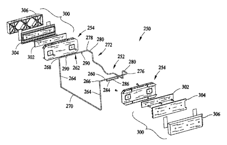
Bottom pan I22 is supported by a support assembly 250 that facilitates
extension and retraction of pan 122 from fresh food compartment 102. Support
assembly 2S0 includes a wire frame 252, and right and left brackets 254, which
in an
exemplary embodiment are substantially identical. Bottom pan 122 is received
within
wire frame 252 for snap fit engagement as will be described. Wire frame 2S2 is
continuously formed and includes spaced apart right and left side arms 260 and
262
respectively. Front leg members 264 extend downwardly from forward ends 266
and
268 of side arms 260 and 262 respectively, and are joined by a front cross
member
270. A rear cross member 272 connects rearward ends 276 and 278 of side arms
260
and 262 respectively. Rear cross member 272 includes pan mounting sections
280.
Rear cross member 272 is formed to substantially conform to cutout portion 187
in
rear wall 186.
Right side arm 260 includes a U-shaped member 284 attached thereto
and defining a channel 286 between U-shaped member 284 and right side arm 260.
U-shaped member 284 and channel 286 define a mounting location for right
bracket
254. Left side arm 262 includes a pair of hooks 290 attached thereto that
define a
mounting location for left bracket 254.
-6-
09HR25403
CA 02465598 2004-04-29
A slide assembly 300 is coupled to each bracket 254. Slide assemblies
300 facilitate sliding movement of pan 122 out of and into fresh food
compartment
102. Each slide assembly 300 is of well known construction and includes a
slide pan
302, a slide liner 304 and a slide spacer 306. Slide pan 302 is coupled to
bracket 254
while slide liner 304 and slide spacer 306 are attached to an interior wall of
fresh food
compartment 102. Slide assembly 300 is a full extension slide assembly that
allows
easy access to the contents of pan 122.
Figure 4 illustrates bracket 254 in detail. Bracket 254 includes a
generally C-shaped channel 320 that includes a side wall 322, a first -rail
324 and an
opposite second rail 326. First rail 324 includes apertures 328 and a lip 330.
Apertures 328 are positioned on first rail 324 so as to coincide with and
receive hooks
290 on left side arm 262. Second rail 326 includes slots 332 and a lip 334.
Slots 332
extend across the width of rail 326 and also through lip 334 such that rail
326 is
formed with a center section 340 between a pair of end sections 342. Center
rail
section 340 is sized to be received in channel 286 of right side arm 260.
The operation of pan support assembly 250 will be described with
reference to Figures 5 and 6. Brackets 254 are used in pairs and are mounted
on right
side arm 260 (Figure 5) and left side arm 262 (Figure 6) inversely oriented
from each
other, that is, on right side arm 260, rail 326 is the upper rail, while on
left side arm
262, rail 324 is the upper rail. It is to be understood that in alternative
embodiments,
this relationship could be reversed.
With reference to Figure 5, bracket 254 is mounted on right side arm
260 by placing lip 334 of center rail section 340 into channel 286 and
rotating bracket
254 in the direction of arrow A so that bracket 254 is suspended. from U-
shaped
member 284. Thus, bracket 254 is mounted on right side arm 260 without tools.
Conversely, bracket 254 is removable from right side arm 260 without tools,
With reference to Figure 6, bracket 254 is mounted on left side arm
262 by inserting hooks 290 into apertures 328 in rail 324 and rotating bracket
254 in
the direction of arrow B so that bracket 254 is suspended from hooks 290.
Thus,
09HR25403
CA 02465598 2004-04-29
bracket 254 is also mounted on left side arm 262 without tools and similarly
is
removable from left side arrn 262 without tools.
Bottom pan 122 is received within wire frame 252 with support
members 188 resting on wire frame side arms 260 and 262. Pan rear wall
engagement
tabs 190 engage mounting sections 280 of wire frame rear cross member 272
providing rearward support for bottom pan 122. Wire frame front cross member
270
is received in snap fit engagement with groove 191 in forward edge 192 of
bottom
wall 184 thus securing pan 122 in wire frame 252. Thus bottom pan 122 is also
installed in wire frame 252 without tools.
Figure 7 and 8 illustrate an alternative embodiment of a wire frame 452
support for bottom pan 122. Wire frame 452 is used in conjunction with right
and left
support brackets 254 as shown in detail in Figure 4. Wire frame 452 includes a
right
side arm 460 and a left side arm 462 and right and left front legs 464 and 465
respectively that extend downwardly from right and left side arms 460 and 462.
Right
side arm 460 and left side arm 462 include U-shaped members 484 and 485
respectively and channels 486 and 487 respectively fox mounting support
brackets
254. Right side arm 460 and right front leg member 464 deftne a plane 492 that
includes right U-shaped member 484. In other words, right side arm 460 and
right
front leg member 464 form a right front portion and U-shaped member 484 is
aligned
with the right front portion. Left side arm 462 and left front leg member 465
form a
left front portion which defines a plane 494. U-shaped anember 4$5 of left
side arm
462 extends exterior from plane 494 in the direction of arrow C. Ire other
respects,
wire frame 452 is similar to wire frame 252, previously described.
For right side arm 460, support bracket 254 is mounted as described
above with respect to right side arm 260 and with reference to Figure 5. For
left side
arm 462, support bracket 254 is mounted as shown in Figure 8. Bracket 254 is
mounted on left side arm 462 by placing lip 334 of center rail section 340
into channel
487 and rotating bracket 254 in the direction of arrow D so that bracket 254
is
suspended from U-shaped member 485.
_g_
09HR25403
CA 02465598 2004-04-29
The embodiments thus described provide a bottom pan support
assembly that can be easily removed and installed by an end user and requiring
no
tools for disassembly and assembly. The design is robust and reliable and easy
to
maintain. The assembly uses few parts which, when combined with simple
installation without tools, lowers production costs. Additionally, service
technicians
require no extra taols to service the assembly.
While the invention has been described in terms of various specific
embodiments, those skilled in the art will recognize that tlae invention can
be practiced
with modification within the spirit and scope of the claims.
_9_