Note: Descriptions are shown in the official language in which they were submitted.
CA 02465721 2006-O1-30
-1-
QUICK CHANGE CASKET CORNER ATTACHMENT MECHANISM
Field of the Invention
The present invention relates generally to caskets, and, more
specifically, to apparatus for attaching decorative corner trim pieces to the
corners of a
casket.
Backqround of the Invention
Some casket designs incorporate decorative or ornamental corner
pieces secured to the casket during fabrication thereof. In many, if not most,
prior
designs, these ornamental corner pieces are rigidly affixed to the casket
shell.
Consequently, if a customer purchasing the casket is not pleased with the
particular
pre-installed ornamental corner pieces, and wishes to customize the casket
exterior to
his or her taste, the funeral director must go through a lengthy and
complicated
process to first remove the original ornamental corner pieces and then
reinstall the
ornamental corner pieces chosen by the customer. This process typically
requires
manual manipulation
CA 02465721 2004-04-29
-2-
and access to the interior of the casket which may require the removal of
bedding, lining, and the like. Such a process is time consuming and can
damage the otherurise new casket and is thus frowned upon and generally
avoided by the funeral director.
To more effectively market caskets, the funeral director desires
to offer a wide variety of ornamental comer pieces from which a customer can
select according to the customer's taste. However, to offer such a wide
selection, and to avoid the undesirable practice mentioned above, the funeral
director would have to maintain a large inventory of many different casket
materiaUfinish and corner piece combinations, which is also undesirable. To
minimize the required inventory of finished caskets, the funeral director
could
simply have one casket of each materiaUfinish provided that the funeral
director had some means providing for the quick and efficient changing of the
ornamental comer pieces on each casket. As such, the customer could quickly
view numerous corner pieces on a single casket, and the funeral director
would need only stock a single casket of each materiaUfinish. Prior casket
designs, which rigidly affix the ornamental comer pieces, do not permit such
quick and efficient changing of the ornamental corner pieces as discussed
above.
What is needed, therefore, is an attachment mechanism to
permit the quick and efficient installation and removal of ornamental corner
pieces onto and from caskets. The attachment mechanism should also permit
attachment of existing ornamental corner pieces which are designed to be
CA 02465721 2004-04-29
-3-
rigidly attached, i.e., allow for retrofitting of current fixed comer pieces
such
that they, too, are quickly and efficiently installed and removed.
Summary of Invention
The present invention overcomes the shortcomings of prior
ornamental corner pieces. In accordance with the principles of the present
invention, the ornamental corner piece includes a back plate which is adapted
to mount to the corner of a casket. An attachment clip is operatively mounted
within an elongated groove in the back plate. The clip member has at Least
one keyhole groove comprising an opening and a slot. An ornamental comer
insert has at Least one attachment member which selectively slidingly engages
the keyhole groove in the attachment clip such that the ornamental corner
insert may be selectively mounted to or removed from the back plate.
Advantageously, the attachment member is a shoulder screw having a head
sized to fit through the opening and be held by the slot. The slot includes
protrusions which act to positively secure the shoulder screw into the slot.
In one aspect of the invention, the attachment clip includes an
indexing member. When the attachment clip is installed, the indexing
member extends into a throughhole in the elongated groove in the back plate.
The indexing member properly orients the attachment clip in the elongated
groove. Advantageously, the indexing member is positioned closer to one end
of the attachment clip than the other. As such, the attachment clip can be
inserted into the elongated groove in only one orientation. By allowing the
attachment~clip to be oriented in only one orientation, the ornamental corner
CA 02465721 2004-04-29
-4-
insert is always installed or removed in a standard method. For example, the
ornamental comer insert might always be installed by slidingly engaging the
attachment clip from left to right and removed by slidingly disengaging the
attachment clip from right to left.
In another embodiment of the invention, the ornamental corner
piece includes a base member which is adapted to mount to the corner of a
casket. A back plate operatively mounts to the base member. An ornamental
comer insert having at least one attachment member selectively slidingly
engages a keyhole groove in the back plate such that the ornamental corner
insert may be selectively mounted to or removed from the back plate.
In still another aspect of the invention, a casket includes a shell
having a pair of side walls and a pair of end walls. At least one corner is
disposed between adjacent side walls and end walls such that the corner is
angled relative to them both. The comer includes at least one keyhole grove.
The casket further includes an ornamental comer insert having a front and a
back side. The ornamental corner insert includes at least one attachment
member on its back side. The attachment member is adapted to be
removeably slidingly received in the keyhole groove via a sliding motion
which is parallel to a plane defined by the corner. Advantageously, the
attachment member is a shoulder screw. The casket may include a back plate
which is operatively mounted to the comer. The back plate, not the comer,
includes the keyhole groove for receiving the attachment member.
CA 02465721 2004-04-29
-5-
In yet another embodiment of the invention, a casket comprises
a shell, an ornament, a first attachment element operably associated with the
shell and a second attachment element operably associated with the
ornament. The first and second attachment elements removably secure the
ornament to the shell. The first and second attachment elements are
configured such that the ornament is removably secured to the shell via
motion in first and second non-parallel directions generally parallel to a
plane
defined by the first attachment element.
The first attachment element is preferably a plate with at least
one groove therein and the second attachment element is preferably at least
one stud. The groove preferably includes a first keyhole portion and a second
non-keyhole portion. The first keyhole portion has a first longitudinal axis,
the
second non-keyhole portion has a second longitudinal axis, and preferably the
first and second longitudinal axes are non-parallel. Preferably, the first and
second longitudinal axes are perpendicular. The stud is preferably a screw,
for
example a shoulder screw. The motion in the first and second directions is
preferably rectilinear.
In stilt another embodiment of the invention, apparatus for
removably securing an ornament to a casket shell comprises a first attachment
element adapted to be operably associated with the shell and a second
attachment element adapted to be operably associated with the ornament.
The first and second attachment elements are configured such that the
ornament is removably secured to the shell via motion in first and second non-
CA 02465721 2004-04-29
-6-
parallel directions generally parallel to a plane defined by the first
attachment
element.
Various additional advantages, objects and features of the
invention will become more readily apparent to those of ordinary skill in the
art upon consideration of the following detailed description of the presently
preferred embodiments taken in conjunction with the accompanying
drawings.
Detailed Description of Drawings
Fig. 1 is a perspective view of a casket embodying the corner
attachment mechanism of the present invention;
Fig. 2 is a disassembled perspective of the corner attachment
mechanism shown in Fig. 1;
Fig. 3 is a plan view of the attachment clip shown in Fig. 2;
Fig. 4 is a partial cross-sectional view of the assembled comer
attachment mechanism of Fig. 3 taken along line 4-4;
Fig. 5 is a partial cross-sectional view of the comer attachment
mechanism of Fig. 3 taken along line 5-5 with the screw removed for clarity;
Fig. 6 is a partial cross-sectional view of another assembled
corner attachment mechanism similar to the one in Fig. 4;
Fig. 7 is a partial cross-sectional view of the ornamental corner
insert of Fig. 4 affixed to a casket corner without using the attachment clip
of
Fig. 3;
CA 02465721 2004-04-29
_ 7
Fig. 8 is disassembled perspective view of another embodiment
of the corner attachment mechanism of the present invention;
Fig. 9 is a broken-away side view of the fastenings means
holding together the base and back plate of Fig. 8; and
Fig. 10 is a view similar to Fig. 8 of yet another embodiment of
the comer attachment mechanism of the present invention.
Detailed Descr~tion of Preferred Embodiments
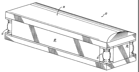
With reference to Fig. 1, a casket 10 is shown incorporating the
comer attachment mechanism 12 of the present invention. The casket has a
top 14, a pair of oppositely disposed end walls 16 and two oppositely
disposed side walls 18. Advantageously, the casket 10 may be made from
wood, although the corner attachment mechanism 12 is not limited to use on
wooden caskets, i.e., the corner attachment mechanism 12 has equal
applicability to metal caskets.
With further reference to Fig. 2, end walls 16 and side walls 18
are joined by brace or mounting member 20. .Brace 20 includes throughhole
22 which, as described below, is sometimes used to mount corner attachment
mechanism 12 to the casket 10. The ends of end wall 16 and side wall 18 do
not meet such that an opening 24 is formed which provides access to the
interior of the casket 10. Comer attachment mechanism 12 includes a back
plate 30, an attachment clip 32, and an ornamental corner insert 34. The
back plate 30 includes end pieces 36, 38 joined by vertical member 40.
Vertical member 40 includes ari elongated groove 42 with a throughhole 44
CA 02465721 2004-04-29
_ 8
extending from the front side of the vertical member 40 to the back side of
vertical member 40. Vertical member 40 is secured to brace 20 by fasteners
45. Fasteners 45 could be screws, nails, brads and the like, but are
preferably
screws. Vertical member 40 is preferably wood but could be made from any
suitable structural material such as steel, aluminum, plastic or the like.
With reference to Figs. 2-5, attachment clip 32 is sized to rest
within and conform to the elongated groove 42. Attachment clip 32 is
removably affixed to vertical member 40 with fasteners 46 inserted through
throughholes 48 in attachment clip 32. Fasteners 46 are preferably screws.
Attachment clip 32 includes an indexing member 49 (Fig. 4) with throughhole
50 which aligns with and penetrates throughhole 44 when attachment clip 32
is placed into elongated grove 42. Indexing member 49 is positioned closer to
the upper end of attachment clip 32 than the lower end. As a result of the
offset position of indexing member 49, the attachment clip 32 can be inserted
into elongated groove 42 in only one orientation. As such, the installation
and
removal of the ornamental corner insert 34 will be consistent for all caskets
10.
That is, the ornamental comer insert 34 will always be installed by sliding it
from left to right and removed by sliding it from right to left.
With specific reference to Figs. 4 and 5, attachment clip 32
further includes two keyhole grooves 52, 54. Keyhole grooves 52, 54 include,
respectively, openings 56, 58 and slots 60, 62. Slots 60, 62 are partly formed
by oppositely disposed rib members 64, 66. Each rib member 64, 66 includes
a protrusion 68, 70. As will be explained in greater detail below, protrusions
CA 02465721 2004-04-29
_9_
68, 70 assist in attaching ornamental corner insert 34 to the attachment clip
32.
Ornamental comer insert 34 includes a decorative or
ornamental side 80 and a mounting side 82. Generally, the decorative side
80 can be of any aesthetically pleasing shape. Mounting side 82, however, is
preferably, but not necessarily, flat so that the ornamental comer insert 34
can
be flushly mounted to vertical member 40. Threaded inserts 84, 86, 88 are
flush mounted to mounting side 82. As shown in Fig. 2, fasteners, and,
preferably, shoulder screws 90, 92, are threaded into threaded inserts 84, 88.
Shoulder screws 90, 92 include heads 94, 96 and shoulder members 98, 100.
Preferably, the shoulder screws are #14-10 type A, blunt tip shoulder screws
sold by Modular Systems, Inc. of Fruitport, Michigan. Heads 94, 96 are sized
in order that they may fit through openings 56, 58 but not fit through rib
members 64, 66. Accordingly, to attach ornamental corner insert 34 to back
plate 30, the heads 94, 96 of shoulder screws 90, 92 are inserted into
openings 56, 58. The ornamental corner insert 34 is then moved from left to
right, as viewed in Fig. 2, such that the protrusions 68, 70 on rib members
64,
66 positively engage the shoulder screws 90, 92 to hold them in slots 60, 62.
To remove the ornamental corner insert 34 and possibly replace it with one of
a different design, the ornamental comer insert 34 is moved from right to left
until heads 94, 96 are allowed to escape through openings 56, 58.
Advantageously, the design of back plate 30 and attachment
clip 32 may accommodate former ornamental corner inserts which do not
CA 02465721 2004-04-29
-10-
incorporate shoulder screws 90,92. These former ornamental comer inserts
typically have only a threaded rod protruding from its back for securing it to
the corner of a casket. As such and with reference to Fig. 6, a former
ornamental corner insert 112 is shown without inserts 84, 88. In this
configuration, only threaded insert is present to receive threaded rod 114. To
install ornamental corner insert 112 to casket 10, threaded rod 114 is
inserted
through indexing member 49 and throughhole 22 of brace 20. Wing nut 118
threadingly engages threaded rod 114 to secure ornamental comer insert 112
to back plate 30. Former ornamental comer insert 112 is representative of the
comer inserts which must be rigidly affixed to the comer of caskets. Judicious
placement of indexing member 49 allows the former style ornamental corner
inserts 112 to be used with attachment clip 32 and back plate 30, i.e. be
retrofitted according to the principles of the present invention.
Alternatively
threaded insert 86 can be eliminated, with the threaded screw being screwed
directly into the wood, plastic or metal insert.
Advantageously, ornamental corner insert 34 may be installed
onto casket corners not incorporating back plate 30 and attachment clip 32.
That is, ornamental comer insert 34 of the present invention is not restricted
to
use with only back plate 30 and attachment clip 32. Importantly, ornamental
corner insert 34 may be used on caskets which were initially constructed using
former ornamental corner insert 112. Accordingly and with reference to Fig.
7, the ornamental corner insert 34 is shown affixed to a back plate 124. Back
plate 124 is representative of back plates used previously in conjunction with
CA 02465721 2004-04-29
-11-
former ornamental corner insert 112. Back plate 124 is similar to back plate
30; however, back plate 124 does not include elongated groove 42. Because
back plate 124 does not include a place to secure attachment clip 32, shoulder
screws 90, 92 cannot be used to secure ornamental comer insert 34 to back
plate 124. As such, shoulder screws 90, 92 are removed and threaded rod
114 is threaded into threaded insert 86. To install ornamental comer insert 34
to back plate 124, threaded rod 114 is inserted through throughhole 44 and
throughhole 22 and held in place with threaded wing nut 118. The benefit of
using the shoulder screws in conjunction with attachment clip 32 is that the
ornamental corner insert 34 can be installed and removed quickly and
efficiently without having to access the interior of the casket 10. The
embodiments shown in Figs. 5 and 6, however, require the use of hand tools
and access to the interior of the casket 10 in order that wing nut 118 can be
threaded onto threaded rod 114.
The embodiments referenced in Figs. 2-7 are preferably used
with a casket 10 constructed of wood. Another embodiment of the present
invention is used on a casket formed from sheet metal, e.g., steel or
aluminum. Accordingly, and with reference to Fig. 8, a casket 128 made from
steel is shown with a comer attachment mechanism 130. The corner
attachment mechanism 130 includes a base or mounting member 132, a back
plate 134 and an ornamental corner insert 136. Base 132 is affixed to the
corner of casket 128 with fasteners, preferably screws, 138. Base 132 and
back plate are preferably made from plastic. Integrally molded within back
CA 02465721 2004-04-29
-12-
plate 134 are keyhole grooves 140, 142 which are similar to the geometry of
keyhole grooves 52, 54. More specifically, keyhole grooves 140, 142 include
openings 144, 146 and slots 148, 150 which are similar to openings 56, 58
and slots 60, 62. Back plate 134 also includes a plurality of oppositely
disposed fastening members 152 which engage oppositely disposed slots 154
along the vertical edges of base 132 to secure back plate 134 to base 132. In
this embodiment, back plate 134 does not include throughhole 44. As such,
the ornamental corner insert 112, having only threaded insert 86, cannot be
attached to base 132. Like the attachment clip 32 of Fig. 2, the back plate
134 permits the ornamental corner insert 136 to be installed from left to
right
and removed from right to left. For example, to install the ornamental comer
insert 136, the heads 94, 96 are inserted into openings 144, 146 of keyhole
grooves 140, 142 and slid from left to right across slots 148, 150.
Referring now to Fig. 10, there is illustrated yet another
embodiment of the present invention for use on sheet metal caskets. With like
numbers representing like elements, the primary difference between the Fig.
10 embodiment and the Fig. 8 embodiment is the design and construction of
the grooves 140' and 142' in the plate 134. More particularly, groove 140'
includes a first keyhole portion comprising opening 144' and slot 148', and a
second non-keyhole portion comprising slot 149'. Similarly, groove 142'
includes a first keyhole portion comprising opening 146' and slot 150', and a
second non-keyhole portion comprising slot 151'. As illustrated, the
longitudinal axis of slot 149' is perpendicular to the longitudinal axis of
slot
CA 02465721 2004-04-29
-13-
148'. Similarly, the longitudinal axis of slot 151' is perpendicular to the
longitudinal axis of slot 150'
To install the casket comer ornament 136, the heads 94, 96 are
inserted into openings 144', 146' of grooves 140', 142'; ornament 136 is then
moved generally parallel to a plane defined by plate 134 from left to right
thus
sliding heads 94, 96 from left to right in slots 148', 150'. The ornament 136
is
then moved again generally parallel to the plane defined by plate 134
downwardly thus sliding heads 94, 96 down in slots 149', 151'. The multi-
direction movement to install ornament 136 in the Fig. 10 embodiment
reduces the potential for the ornament 136 to become inadvertently dislodged
from plate 134.
While the two directions of motion to install the ornament 136
in the Fig. 10 embodiment have been illustrated as being perpendicular, the
openings, grooves, etc. could as well be configured such that the directions
of
motion were not perpendicular, but simply non-parallel. Furthermore, while
the motions to install ornament 136 in the Fig. 10 embodiment have been
illustrated as being rectilinear, the openings, grooves, etc. could as well be
configured such that the motions were not rectilinear, but curvilinear. All
such
variations are within the scope of the present invention.
While the present invention has been illustrated by a description
of various preferred embodiments and while these embodiments have been
described in considerable detail in order to describe the best mode of
practicing the invention, it is not the intention of the applicants to
restrict or in
CA 02465721 2004-04-29
14-
any way limit the scope of the appended claims to such detail. Additional
advantages and modifications within the spirit and scope of the invention will
readily appear to those skilled in the art. The invention itself should only
be
defined by the appended claims, wherein we claim: