Note: Descriptions are shown in the official language in which they were submitted.
CA 02465740 2004-04-29
HITCH ASSEMBLY
BACKGROUND OF THE INVENTION
Field of the Invention
[0001] The present invention relates to a hitch assembly for attachment to a
conventional drawbar of a towing vehicle with a pin slot providing a more
rigid
support over rough terrain.
Prior Art
[00021 A conventional towing hitch comprises a towing ball member and a
fastener. Typically, in practice a trailer tongue is placed on the towing ball
member
mounted on the drawbar of a towing vehicle. The towing ball member consists of
a
pin with a ball head inserted into a hole in the drawbar and secured thereto
by a
fastener. The main problem with this design is the instability of the hitch
when
subjected to dips and bumps while driving along rough terrain. Due to the fact
that
the trailer is being pulled by the towing vehicle, the former comes into
contact with
the uneven terrain after the towing vehicle has already reacted to it;
therefore
working to oppose the motion of the latter. Thus, as the towing vehicle is in
motion
the pin is subjected to various forces resulting from the slackness present
between the
pin and the drawbar. Very frequently the pin breaks due to the concentration
of
forces on the pin. Not only is this an inconvenience to the driver of the
vehicle but it
is also a cause for numerous trailer accidents each year.
[00031 The conventional towing hitch presently employed is unstable,
unreliable and potentially hazardous to use. Consequently, it is desired to
improve the
rigidity while maintaining the versatility of the towing hitch in order to
ensure that it
is functional and securable under most road conditions. What is currently not
available is a hitch assembly, propitiously suited for rigid attachment to a
drawbar of
a towing vehicle with a pin slot that is easily installable yet versatile and
provides the
stability required to make an effective towing hitch.
-1-
CA 02465740 2004-04-29
SUMMARY OF THE INVENTION
[00041 In accordance with a general aspect of the present invention there is
provided a hitch assembly for attachment to a drawbar of a towing vehicle with
a pin
slot, comprising: a mounting bracket defining a horizontal through adapted to
receive
the drawbar, a pin projecting downwards into the through for engagement in the
pin
slot, a wedge axially insertable into the through for wedging the drawbar in
the
through, and a fastener for releasably securing the wedge to the mounting
bracket.
[0005 In accordance with a further aspect of the present invention, there is
provided a method for installing a hitch assembly for attachment to a drawbar
of a
towing vehicle with a pin slot, the method comprising the steps of: fitting a
mounting
bracket over the drawbar with a pin proj ecting inwardly from the mounting
bracket in
engagement with the pin slot, and wedging the drawbar in place within said
mounting
bracket.
[00061 In accordance with a further general aspect of the present invention,
there is provided a hitch assembly mountable to a drawbar of a towing vehicle
for
towing a steerable trailer, comprising a mounting bracket carrying a towing
ball
member and adapted to be releasably securely mounted to the drawbar, a trailer
steering mechanism engaging member extending outwardly from said mounting
bracket for communicating steering movements from the towing vehicle to the
steerable trailer.
[000'71 These and other aspects and advantages of the invention will become
more apparent from the following detailed description when taken in
conjunction
with the accompanying drawings.
BRIEF DESCRIPTION OF THE DRAWINGS
[ooosl Having thus generally described the nature of the invention, reference
will now be made to the accompanying drawings, showing by way of illustration
a
preferred embodiment thereof and in which:
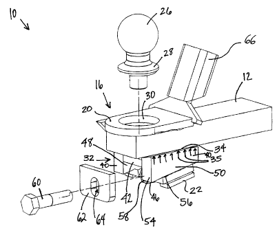
[00091 Fig. 1 is a perspective view of a hitch assembly adapted to be mounted
on a drawbar of a towing vehicle, in accordance with a preferred embodiment of
the
present invention;
-2-
CA 02465740 2004-04-29
[00010) Fig. 2 is an exploded view of a hitch assembly mounted on a drawbar
of a towing vehicle; and
[00011) Fig. 3 is a perspective view of a hitch assembly mounted on a drawbar
of a towing vehicle and secured thereto.
DETAILED DESCRIPTION OF PREFERRED EMBODIMENTS
[00012) Referring to the drawings and particularly to Fig. 1, a hitch assembly
in accordance with an embodiment of the present invention is shown at 10. A
drawbar 12 of a towing vehicle with a pin slot 14 is also shown, whereby the
hitch
assembly 10 may be mounted thereto by any convenient manner. The hitch
assembly
comprises a mounting bracket 16 defining a horizontal through 18 for receiving
the drawbar 12. As a preferred embodiment of this invention, the horizontal
through
18 is defined more specifically by a top portion 20, a bottom portion 22 and
two side
portions 24 making up the core structure of the mounting bracket 16.
Particularly the
top, base and side portions, 20, 22, and 24 respectively are prismatically
moulded
together such that they define a horizontal through able to receive a drawbar
12 of
varying height and width.
[00013[ Refernng now to Fig. 2, the hitch assembly 10 also comprises a pin 26
for engagement in the pin slot 14 of the drawbar 12. Preferably, the pin 26 is
an
integral part of the mounting bracket 16 so that the hitch assembly 10 is
rigid. Thus,
the rigidity of the hitch assembly 10 is one factor which contributes to
reduce the
concentration of forces on the pin 26 when the towing vehicle is in motion,
resulting
in less pin breakages than with the hitch assembly described in the prior art.
In the
present embodiment, the pin 26 is integrally joined to the top portion 20
projecting
downwards into the horizontal through 18 for engagement in the pin slot 14 of
the
drawbar 12. The pin 26 has a tapered skirt 28, which fits into a complementary
tapered aperture 30 defined through the top portion 20 of the mounting bracket
16.
The pin 26 is permanently secured in the aperture 30, such as by welding or
other
thermal fusion processes. As a result, the slackness present in the hitch
assembly
described in the prior art is eliminated by securely fitting the pin 26 to the
mounting
bracket 16.
-3-
CA 02465740 2004-04-29
[00014] In addition, the hitch assembly 10 further comprises a wedge 32
axially insertable into the horizontal through 18 for wedging the drawbar 12
therein,
as shown in Figs 2 and 3. Preferably, the wedge 32 is insertable between the
drawbar
12 and the base portion 22 of the mounting bracket 16 such that there is a
uniform
contact surface 34 (Fig. 2) between the wedge 32 and the drawbar 12 whereby
uniform pressure is applied thereto, as depicted by arrows 35 in Fig. 2.
Notably, the
wedge 32 can be inserted into the through 18 of the mounting bracket 16 by the
same
or opposing horizontal entrance as the entrance by which the drawbar 12 was
received; however the invention will be described from hereon as presented in
the
accompanying drawings, with the insertion of the wedge 32 opposing that of the
drawbar 12. Moreover, for further clarification, the entrance receiving the
drawbar 12
will be referred to from hereon as the front entrance 36 while the entrance
receiving
the wedge 32 will be referred to from hereon as the rear entrance 38 (see Fig.
1).
[00015] Advantageously, the present invention is characterized by its
versatility in that it is adaptable for a drawbar 12 of varying thickness and
width.
More specifically, the wedge 32 in combination with the base portion 22 of the
mounting bracket 16 allows for the drawbar 12 to vary in thickness, and the
structural
integrity of the wedge 32 allows for the drawbar 12 to vary in width.
[00016 In a preferred embodiment of this invention, the wedge 32 is
composed of two side segments 40 separated by a flat horizontal segment 42, as
shown concurrently in Figs. 1 and 2. The side segments 40 are each polyhedrons
including six facets: rectangular top and bottom facets 44 and 46, polygonal
inner
and outer side facets 48 and 50, and polygonal front and rear facets 52 and 54
respectively. Preferably, the flat horizontal segment 42 separates the inner,
polygonal, side facets 48 and is moulded thereto to maintain the structural
integrity of
the wedge 32. Alternatively, the wedge could be molded from a single piece of
material
[00017] Furthermore, referring concurrently to Figs. 1 and 2, the rectangular
top facets 44 are sloped inwards, towards the flat horizontal segment 42,
enabling the
wedge 32 to accept a drawbar 12 of varying width. Thus, the contact surface 34
between the wedge 32 and the drawbar 12, as abovementioned and best
illustrated in
Fig. 2, can develop anywhere along the slope of top facets 44 depending on the
width
-4-
CA 02465740 2004-04-29
of the drawbar 12. As the width of the drawbar 12 increases, the contact
surface 34
moves up the slope of the top facets 44 accordingly. Similarly, as the width
of the
drawbar 12 decreases, the contact surface 34 develops further down along the
decline
of the top facets 44. The bottom facets 46 differ from the top facets 44 by
the
manner in which they are sloped. The former are sloped to form the wedge shape
such that the rear facets 54 are larger in surface area than the front facets
52.
Suitably, the base portion 22 of the mounting bracket 16 adapted for receiving
the
bottom facets 46 of the side segments 40 can be described as having a
corresponding
sloped surface 56.
100018] Moreover, the hitch assembly 10 comprises a fastener for releasably
securing the wedge 32 to the mounting bracket 16. In one embodiment of the
present
invention the wedge 32 can be fastened by way of a nut 58 and a bolt 60 as
illustrated
in both Figs. 1 and 2. The nut 58 is preferably integrally mounted to the base
portion
22 of the mounting bracket 16, such as by welding. It is centrally located in
the base
portion 22 and aligned with the horizontal through 18 facing the rear entrance
38. It
is understood that another form of threaded hole could be provided in the
mounting
bracket instead of the nut 58. Furthermore, the wedge 32 possesses a rear
segment 62
adjacent to the rear facets 54 defining a slotted hole 64 for receiving the
bolt 60 and
securing the wedge 32 to the mounting bracket 16. The slotted hole 64 is
aligned with
the nut 58 and enables the bolt 60 to be inserted therein and attached to the
nut 58
regardless of the position of the wedge relative to the drawbar 12 and the
mounting
bracket 16, as shown in Fig. 3.
100019] As the wedge 32 is inserted by the rear entrance 38 into the
horizontal
through 18, the bottom facets 46 come into planar contact with the sloped
surface 56
of the base portion 22 and the top facets 44 come into contact with the
drawbar 12.
By firmly wedging the drawbar 12 in the through 18 of the mounting bracket 16,
the
contact surface 34 between the wedge 32 and the drawbar 12 is formed uniformly
along all the length of the top facets 44 ensuring that uniform pressure is
applied to
the drawbar 12. The position of the wedge 32 relative to the drawbar 12 and
the
mounting bracket 16 when wedged into the through 18 is based on the thickness
of
the drawbar 12: the smaller the thickness, the further the wedge 32 can be
inserted
-5-
CA 02465740 2004-04-29
into the through 18. Regardless of the position of the wedge 32, the pressure
on the
drawbar 12 remains uniform as long as it is firmly wedged into place.
X00020) Due to the abovementioned embodiments described hereof, the
versatile hitch assembly 10 can be rigidly attached to the drawbar 12 ensuring
its
functionality in that uniform pressure is always applied thereto. This
invention is as a
result more stable due to the uniform pressure application, making it a more
effective
hitch assembly.
100021) With concurrent reference to Figs. 1, 2 and 3, the hitch assembly 10
depicted above will now be incorporated into the method proposed in an
embodiment
of the present invention. With the forgoing arrangement the hitch assembly 10
is
manually attached to the drawbar 12 of a towing vehicle with a pin slot 14 by
way of
the following methodical steps. In carrying out this method, the drawbar 12 is
placed
into the front entrance 36 of the horizontal through 18 of the mounting
bracket 16
and the projecting pin 26 is aligned with the pin slot 14. The pin 26 is then
engaged
into the pin slot 14 such that the mounting bracket 16 is resting on top of
the drawbar
12.
~o0022) As shown in Figs. 1, 2 and 3, a trailer steering engaging member 66
extends upwardly forwardly from the top front portion of the bracket 36. The
trailer
steering engaging member 66 is adapted to be received between a pair of fork
members (not shown) forming part of a pivotable member of a trailer steering
mechanism. The engagement of the member 66 between the fork members provides
for the transmission of motion from the motive vehicle to the trailer. When
the
motive vehicle turns to the left, the engagement of the member 66 between the
fork
members will impart a counterclockwise rotation of the pivotable member of the
trailer steering mechanism. On the other hand, if the motive vehicle turns to
the
right, a clockwise rotation will be communicated to the pivotable member of
the
trailer steering mechanism by the member 66 through the fork members engaged
therewith. This arrangement provides for a trailer steering mechanism which is
responsive to the direction of movement of the motive vehicle.
~00o23) Next, the wedge 32 is inserted into the rear entrance 38 of the
horizontal through 18 so as to wedge the drawbar 12 into place. The wedge 32
is then
secured to the mounting bracket 16 by passing the bolt 60 through the slotted
hole 64
-6-
CA 02465740 2004-04-29
and fastening it to the nut 58. To ensure that the wedge 32 is firmly secured
into
place and applying uniform pressure to the drawbar 12, an axial force of any
kind can
be used to apply pressure to the wedge 32 in order to reposition it further
into the
through 18. An example of such a force could be the impact of hitting the rear
segment 62 of the wedge 32 with a hammer. Finally, if required the wedge is
further
secured to the mounting bracket 16 by tightening the bolt 60.
[00024) The forgoing description of the preferred embodiments is considered
as illustrative only of the principles of the invention. Further, changes and
variations
which are obvious to those skilled in the art are also included in the scope
of this
invention because it is not desired to limit the invention to the exact
construction and
method shown and described.