Language selection

Search

Patent 2465762 Summary

Third-party information liability

Some of the information on this Web page has been provided by external sources. The Government of Canada is not responsible for the accuracy, reliability or currency of the information supplied by external sources. Users wishing to rely upon this information should consult directly with the source of the information. Content provided by external sources is not subject to official languages, privacy and accessibility requirements.

Claims and Abstract availability

Any discrepancies in the text and image of the Claims and Abstract are due to differing posting times. Text of the Claims and Abstract are posted:

  • At the time the application is open to public inspection;
  • At the time of issue of the patent (grant).
(12) Patent Application: (11) CA 2465762
(54) English Title: TRANSFER HEAT PRESS
(54) French Title: PRESSE A TRANSFERT DE CHALEUR
Status: Dead
Bibliographic Data
(51) International Patent Classification (IPC):
  • B41F 1/02 (2006.01)
  • B30B 7/02 (2006.01)
  • B41F 15/08 (2006.01)
  • B41F 15/12 (2006.01)
(72) Inventors :
  • EPPINGER, OTTO RICHARD (Australia)
(73) Owners :
  • REEFDALE PTY LTD (Australia)
(71) Applicants :
  • REEFDALE PTY LTD (Australia)
(74) Agent: OSLER, HOSKIN & HARCOURT LLP
(74) Associate agent:
(45) Issued:
(22) Filed Date: 2004-04-30
(41) Open to Public Inspection: 2004-12-03
Availability of licence: N/A
(25) Language of filing: English

Patent Cooperation Treaty (PCT): No

(30) Application Priority Data:
Application No. Country/Territory Date
2003902747 Australia 2003-06-03
2003906205 Australia 2003-11-12

Abstracts

English Abstract


A transfer heat press which is intended for use with a rotary screen printing
machine, incorporates a C shaped frame mounted on a support and moveable
vertically relative to said support. A heater platen is mounted to the top of
the C
frame. A lower platen adapted to support the pallet of the rotary screen
printing
machine is mounted on the lower part of the C frame. The lower platen is
moveable toward the upper platen. The lower platen applies a force to the
underside of the pallet arm of a screen printing machine which results in the
platen frame being allowed to move downwardly. This downward movement is
guided and cushioned by a pneumatic or hydraulic spring. This arrangement
means that the force on the pallet arm is equal to the weight of the platen
frame
less the upthrust of the pneumatic hydraulic ram. This reduces the risk of
damage
to the pallet arm.


Claims

Note: Claims are shown in the official language in which they were submitted.


6


CLAIMS

1. A printing machine arm and press combination in which the printing machine
has a pallet arm for supporting an article to be printed and the press
includes
a) a platen frame, adapted to encompass the pallet arm, mounted on a
support and moveable vertically relative to said support
b) an upper platen, adapted to lie above the pallet arm, mounted to the platen
frame
c) a lower platen mounted on the platen frame the lower platen being
positioned below the pallet arm upwardly moveable to abut the pallet arm
d) control means which allows the frame to move downwardly when the lower
platen is raised.
2. A transfer heat press which includes
a) a platen frame mounted on a support and moveable vertically relative to
said support
b) an upper platen mounted to the platen frame incorporating means to heat
said upper platen
c) a lower platen mounted on the platen frame the lower platen being
moveable toward the upper platen
d) control means which allows the frame to move downwardly when the lower
platen is raised toward the upper platen.
3. A transfer heat press as claimed in claim 2 in which the platen frame is a
C
shaped frame.
4. A transfer heat press as claimed in claim 2 in which the platen frame is
supported by a pneumatic or hydraulic ram.
5. A transfer heat press as claimed in any preceding claim in which the lower
platen reciprocates relative to the press frame.

Description

Note: Descriptions are shown in the official language in which they were submitted.


CA 02465762 2004-04-30
Transfer Heat Press
This invention relates to a heat press for transfer printing of garments
particularly
in association with a rotary screen printing machine.
Background to the Invention
Heat presses for transfer printing are known. USA patent 4386993 discloses a
press in which the upper platen moves relative to the lower platen by way of a
cam
and rocking member.
USA patent 3979248 discloses a decal press with a motor driven upper platen.
USA patent 5435883 discloses a hand operated press with adjustment for the gap
between the platens.
USA patent 5474633 discloses a press with a pneumatic engager to press the
upper platen onto the lower platen and a timer mechanism.
USA patent 4963208 discloses a system for applying a decorative device using a
swingable upper platen.
Often transfers are applied as part of a process of screen printing an
ornamental
pattern onto a garment. The heat press is positioned relative to one print
station of
a rotary printing machine of the type described in USA patents 3795189 and
5031527 which are examples of the type of machines used in screen printing
garments. The garment is supported on a pallet of the screen printing machine
and
the pallet arm swings the pallet with the garment into position between the
upper
and lower platens of the heat press.
In the prior art heat presses the pressing force is applied by the upper
platen and
the lower platen may not be at an appropriate height to properly support the
pallet
arm. The forces applied may damage the pallet arm or bend it out of shape
sufficient to impede the printing performance of the machine.
One attempt to overcome this problem is disclosed in USA patent 5970874 where
both the upper and lower platens are movable relative to the heat press frame
so
that the upper and lower platens simultaneously press the pallet. In practice
however it is difficult to achieve simultaneous contact and undue pressure on
the
pallet arms still occurs.
It is an object of this invention to overcome this problem.


CA 02465762 2004-04-30
2
Brief Description of the Invention
To this end the present invention provides a transfer heat press which
includes
a) a platen frame mounted on a support and moveable vertically relative to
said support
b) an upper platen mounted to the platen frame
c) a lower platen mounted on the platen frame the lower platen being
moveable toward the upper platen
d) control means which allows the frame to move downwardly when the lower
platen is raised toward the upper platen.
The lower platen applies a force to the underside of the pallet arm of a
screen
printing machine which results in the platen frame being allowed to move
downwardly. This downward movement is preferably guided and cushioned by a
pneumatic or hydraulic spring. This arrangement means that the force on the
pallet
arm is equal to the weight of the platen frame less the upthrust of the
pneumatic
or hydraulic spring and the risk of damage to the pallet arm is minimized. The
pressure applied by the upper platen to a garment is counterbalanced by the
upward force exerted by the lower platen. This is a more reliable means of
ensuring that the pressure on the pallet is always countered by the lower
platen
than that provided by USA patent 5970874.
Preferably the platen frame is C shaped and the upper platen is fixed to the
top of
the C and the lower platen is able to be raised toward the upper platen. The C
frame and the upper and lower platens are supported by a support frame which
may include hydraulic or pneumatic lifting rams to initially place the C frame
around the pallet of the screen printing machine. Once the heat press is
actuated
the lower platen is raised to contact the pallet arm and the C frame is
allowed to
slide downwardly so that the upper platen contacts the garment on the pallet.
The upper platen is heated to assist the transfer printing.
Detailed Description of the Invention
A preferred form of the invention is illustrated in the enclosed drawings in
which
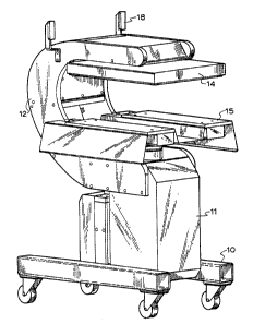
Figure 1 is a rear perspective view of the heat press of this invention;
Figure 2 is front perspective view of the heat press of this invention;


CA 02465762 2004-04-30
3
Figure 3 is a schematic side elevation of the invention; and
Figure 4 is a schematic rear view of the invention.
The embodiment illustrated is a mobile heat press station which may be used
with
a rotary or oval screen printing machine of the kind described in USA patents
5031527, 5595113, 5678482, 5913264 and 5970874 or any other printing
machine with a cantilevered pallet.
The machine consists of a wheeled base 10 mounted on which is the support
frame 11. The C frame 12 is mounted for vertical sliding movement on the
support
11 and carries the heater platen 14 which is the upper platen and the pallet
support or lower platen 15. Location guides 18 are adapted to locate the heat
press against the print station of a print machine so that each pallet will be
aligned with the upper platen 14 and lie between the platens 14 and 15. The
heat
press includes a micro controller and controls 17 that can be programmed as to
the duration and temperature of the transfer printing operation. As shown in
more
detail in figures 3 and 4 the heating platen 14 is >:Ixed to the upper portion
of the C
frame 12 by the attachment means 21. During operation of the heating press of
this invention, the heating platen 14 does not move relative to the C frame
12.
Attached to the C frame is the press cylinder 24 which is adapted to raise and
lower the pallet support platen 15. The swivel hub 22 allows for relative
movement
between the press cylinder shaft and the pallet support 15.
The C frame12 is supported by the levelling cylinder 28 which in turn is fixed
by
the frame 25 to the base 10. The guide rails 26 sliding within the bearings 27
ensure that the C frame slides vertically in response to the pressure in the
levelling
cylinder 28. The cylinder 28 allows the C frame 12 and its attachments the
upper
platen 14 and the lower platen and its press cylinder 24 to float downwardly
as the
lower platen is raised. The levelling cylinder 28 may be an hydraulic cylinder
but is
preferably a pneumatic ram.
!n operation the levelling cylinder 28 is pressured to ensure that the pallet
of the
rotary screen printing machine is located underneath the platen 14 and above
the
pallet support 15. When the pressing operation commences the press cylinder
raises the lower pallet 15 so that it abuts and supports the pallet and pallet
arm.
The air in the pneumatic cylinder 28 is allowed tv bleed so that the cylinder
28 acts
as a spring and takes the weight of the C frame12 and its attachments. This


CA 02465762 2004-04-30
4
means that the full weight of the C frame 12, the platens 14 and 15 is
countered
by the levelling cylinder 28 while the pallet is supported by the press
cylinder 24.
By this arrangement damage to the pallet arm of the screen printing machine is
avoided.
The sequence of operation of the heat press when used in conjunction with a
rotary screen printing machine is
1. -The pallet of the rotary screen printing machine swings into position
between the top (heated) platen and bottom (support) platen
2. the pallet is raised toward the heated platen by the rotary screen printing
machine mechanism
3. the lower platen is raised to contact the pallet
4. the bleeding of air from cylinder 28 means that the frame and top platen
are
counterbalanced by the lower platen
5. heat is applied to the garment on the platen by the top platen which is in
contact with the garment on the pallet
6. the bottom platen is lowered
7. the pallet is lowered
8. the pallet swings out and the next pallet swings in to repeat the cycle.
A safety cage may be provided on either side of the heat press so that the
space
between the platens and the pallet is closed off to avoid accidental injury by
the
insertion of a hand or limb during operation of the heat press. When provided
the
safety barrier is raised between steps 3 and 4 and lowered between steps 7 and
8.
The transfer foils may be placed on the garment on the pallet of the rotary
screen
printer prior to the pallet swinging into position under the top platen.
Alternatively
the transfer foil may be mounted on a reel feed which passes the web from a
feed
roll mounted on one side of the heat press frame 12, under the top platen to a
take up roll mounted on the other side of the frame. The take up roll controls
the
tension of the web and a control mechanism ensures that the web is indexed to
move each successive foil image to the correct position under the top platen
so
that the image is transferred from the foil to the garment.


CA 02465762 2004-04-30
Those skilled in the art will realize that other embodiments of the invention
are
possible without departing from the essential principle of this invention.
Those
skilled in the art will also realize that this invention provides a reliable
and unique
means of transfer printing on screen printing machine pallets without
compromising the operation of the screen printing machine.

Representative Drawing
A single figure which represents the drawing illustrating the invention.
Administrative Status

For a clearer understanding of the status of the application/patent presented on this page, the site Disclaimer , as well as the definitions for Patent , Administrative Status , Maintenance Fee  and Payment History  should be consulted.

Administrative Status

Title Date
Forecasted Issue Date Unavailable
(22) Filed 2004-04-30
(41) Open to Public Inspection 2004-12-03
Dead Application 2010-04-30

Abandonment History

Abandonment Date Reason Reinstatement Date
2009-04-30 FAILURE TO REQUEST EXAMINATION
2009-04-30 FAILURE TO PAY APPLICATION MAINTENANCE FEE

Payment History

Fee Type Anniversary Year Due Date Amount Paid Paid Date
Registration of a document - section 124 $100.00 2004-04-30
Application Fee $200.00 2004-04-30
Maintenance Fee - Application - New Act 2 2006-05-01 $50.00 2006-05-01
Back Payment of Fees $50.00 2007-04-23
Maintenance Fee - Application - New Act 3 2007-04-30 $50.00 2007-04-23
Maintenance Fee - Application - New Act 4 2008-04-30 $100.00 2008-04-28
Owners on Record

Note: Records showing the ownership history in alphabetical order.

Current Owners on Record
REEFDALE PTY LTD
Past Owners on Record
EPPINGER, OTTO RICHARD
Past Owners that do not appear in the "Owners on Record" listing will appear in other documentation within the application.
Documents

To view selected files, please enter reCAPTCHA code :


To view images, click a link in the Document Description column. To download the documents, select one or more checkboxes in the first column and then click the "Download Selected in PDF format (Zip Archive)" or the "Download Selected as Single PDF" button.

List of published and non-published patent-specific documents on the CPD .

If you have any difficulty accessing content, you can call the Client Service Centre at 1-866-997-1936 or send them an e-mail at CIPO Client Service Centre.


Document
Description 
Date
(yyyy-mm-dd) 
Number of pages   Size of Image (KB) 
Abstract 2004-04-30 1 23
Description 2004-04-30 5 217
Claims 2004-04-30 1 34
Drawings 2004-04-30 4 118
Representative Drawing 2004-11-03 1 16
Cover Page 2004-11-09 2 51
Assignment 2004-04-30 3 104
Fees 2006-05-01 1 41
Fees 2007-04-23 1 41
Fees 2008-04-28 1 44